


 Loading...
AEC-AMC2-UL1
|
|
|
|
|
|
|
|
|
|
|
|
en |
Installation manual |
||
de |
Installationshandbuch |
||
pl |
Instrukcja instalacji |
||
zh |
|
||
nl |
Installatiehandleiding |
||
ru |
Руководство по установке |
||
hu |
Telepítői kézikönyv |
||
pt |
Manual de instalação |
||
es |
Manual de instalación |
||
fr |
Manuel d’installation |
||

AEC-AMC2-UL1 |
3 |
|
|
English
Deutsch
Polski
Nederlands
Русский
Magyar
Português brasileiro
Español latinoamericano
Français
Bosch Sicherheitssysteme GmbH |
F.01U.097.252 | V 3.2 | 2010.01 |
4 en |
AEC-AMC2-UL1 |
|
|
F.01U.097.252 | V 3.2 | 2010.01 |
Bosch Sicherheitssysteme GmbH |
AEC-AMC2-UL1 - Installation manual |
en 5 |
|
|
Included parts
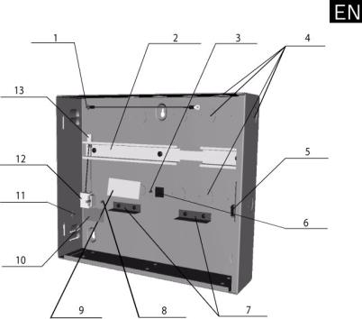
The metal housing inlcudes the following components:
Figure 1 |
Parts of the housing |
1 = |
Cover grounding post |
2 = |
Mounting rail for PS and AMC |
3 = |
AMC grounding post |
4 = |
Cable knock-outs for reader and signal cables |
5 = |
Cover tamper switch |
6 = |
Temperature sensor bracket |
7 = |
Clips for rechargeable batteries |
8 = |
Main grounding post |
9 = |
Name plate |
10 = |
Label |
11 = Power cable knock-out
12 = Three pin connector
13 = Power supply connector
Bosch Sicherheitssysteme GmbH |
F.01U.097.252 | V 3.2 | 2010.01 |
6 en |
AEC-AMC2-UL1 - Installation manual |
|
|
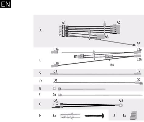
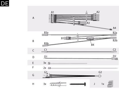
The accessories kit includes the following cables. Install these cables as described in Section Figure 3 Demensions of the housing, page 7.
Figure 2 Accessories kit content
Content of the accessories kit:
A = Pre-assembled cable to connect the AMC to the power supply
B = Pre-assembled cable to connect the rechargeable batteries to the UPS (uninterruptable power supply) which is included in the power supply
C = Cable using 24 V mode
D = Grounding cable for the cover
E = Cable ties to secure the pre-assembled cable G = Pre-assembled cable with temperature sensor
H = Three screw anchors S8 and wood screws M6 x 50 J = Bracket for cable fixing
F.01U.097.252 | V 3.2 | 2010.01 |
Bosch Sicherheitssysteme GmbH |

AEC-AMC2-UL1 - Installation manual |
en 7 |
|
|
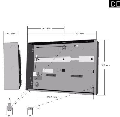
Mounting the Housing
Open the housing cover lock with the provided key and remove the hood from the wall mounted frame.
Mount the metal housing at the desired position with the screw anchors provided with the enclosure.
Use the screws (position H of the accessories kit) at the points to mount the housing against the wall.
Figure 3 Demensions of the housing
Bosch Sicherheitssysteme GmbH |
F.01U.097.252 | V 3.2 | 2010.01 |

8 en |
AEC-AMC2-UL1 - Installation manual |
|
|
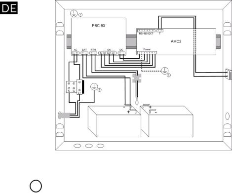
Connection of the Devices
|
Figure 4 |
Connection of the devices |
|
|
|
|
|
|
NOTICE! |
|
|
i |
The following steps describe connecting the rechargeable |
||
batteries in 24 V mode. For information on 12 V mode |
|||
|
connections, refer to Section 12 V Mode Variations, page 11. |
||
|
|
|
|
|
1. |
Mount the AMC on the rail (item 2 in Figure 1) and left |
|
|
|
aside the power supply. |
|
|
2. |
Put the rechargeable batteries on the bottom of the |
|
|
|
housing and secure them with the cable ties F - (Figure 2). |
|
|
3. |
Stick the bracket J (Figure 2) on the back of the housing in |
|
|
|
such a way that later on not used connectors of the cable |
|
|
|
B can fixed with it. |
|
|
4. |
Cable set A: |
|
|
|
a. |
Connect the 7-pin plug A1 to the AMC’s power supply |
|
|
|
connector (labeled: POWER). |
|
|
b. Attach connectors A3 to the PS-interface DC and A2 |
|
|
|
|
to the interface labeled OK. |
|
|
c. |
Connect the grounding cable A4 beneath the |
|
|
|
grounding point 3. |
|
5. |
Cable set B: |
|
F.01U.097.252 | V 3.2 | 2010.01 |
Bosch Sicherheitssysteme GmbH |

AEC-AMC2-UL1 - Installation manual |
en 9 |
|
|
a.Connect the plug connector B1 the second position from the left on the power supply - labeled with BAT.
b.Attach connector B2b (red) to the +-pin of the first rechargeable battery.
c.With cable C connect the --pin of the first rechargeable battery to the +-pin of the second rechargeable battery.
d.Attach connector B2a (black) to the --pin of the second rechargeable battery.
e.Connectors B3a and B3b are not used.
6.Cable set G:
a.Attach connector G1 on the PS-interface labbeled
RTH.
b.Route the cable across the temperature sensor bracket so that the temperature sensor G2 hangs approximitely 5 cm (2 in.) above the rechargeable batteries.
7.Pre-assembled cable set 12:
a.Connect the 2-pin plug 13 on the interface AC of the power supply.
8.Pre-assembled cable :
a.Connect the loose ends of the cover tamper switch to the 2-pin screw connector on the top of the AMC. Position the cable in the space between the housing and the mounting rail.
DANGER!
Remove the fuse from the three-pin connector before proceeding with the power supply connection.
Do not install the fuse before completing the installation procedure.
9.Connect the main AC supply X:
a.Connect the brown (phase) wire to terminal L1.
b.Connect the blue (neutral) wire to terminal N.
c.Connect the grounding cable to the housing at position 11.
CAUTION!
Shorten the external supply wires so that the ground (yellow/
!green) wire is at least 20 mm (0.8 in.) longer than the live (blue and brown) wires. This ensures that the ground wire cannot be accidentally disconnected before life wires.
Bosch Sicherheitssysteme GmbH |
F.01U.097.252 | V 3.2 | 2010.01 |

10 en |
AEC-AMC2-UL1 - Installation manual |
|
|
NOTICE!
Connect the readers and other peripheral devices as described i in the AMC Installation Manuals. Route the device cables
through the knock-outs in the top and right side wall of the housing, or through the rear of the housing.
10.Cable D:
a.Connect D1 to grounding post 1.
b.Connect D2 to the grounding post on the cover.
11.Install the fuse.
12.Close the cover.
F.01U.097.252 | V 3.2 | 2010.01 |
Bosch Sicherheitssysteme GmbH |
AEC-AMC2-UL1 - Installation manual |
en 11 |
|
|
12 V Mode Variations
Figure 5 12 V mode variants
The 12 V mode can be configured using one or two rechargeable batteries. For a one-battery installation, refer to Figure 5 - on the left, and perform the following procedure:
1.Connect B1 to the power supply position labbeled BAT.
2.Connect B2a (black) to the rechargeable battery’s - terminal, and B2b (red) to the rechargeable battery’s + terminal.
3.Connectors B3a and B3b remain unused - fix them with the bracket J.
For the two-battery installation, refer to Figure 5 - on the right, and perform the following procedure:
1.Connect B1 to the power supply position labbeled BAT.
2.Connect B2a (black) to the rechargeable battery’s - terminal, and B2b (red) to the rechargeable battery’s + terminal.
3.Connect B3a (black) to the second rechargeable battery’s - terminal, and B3b (red) to the second rechargeable battery’s + terminal.
Bosch Sicherheitssysteme GmbH |
F.01U.097.252 | V 3.2 | 2010.01 |
12 en |
AEC-AMC2-UL1 - Installation manual |
|
|
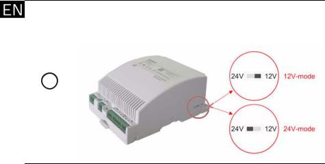
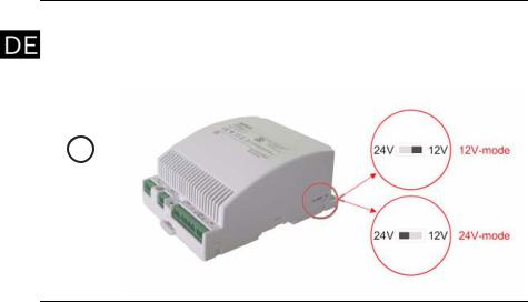
NOTICE!
To switch the power supply between 12 V or 24 V modes, disconnect the input voltage and set the switch as shown in the figure below.
F.01U.097.252 | V 3.2 | 2010.01 |
Bosch Sicherheitssysteme GmbH |
AEC-AMC2-UL1 - Installationshandbuch |
de 13 |
|
|
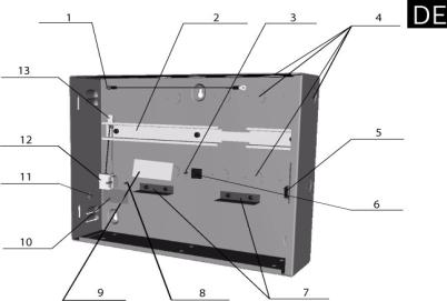
Lieferumfang
Das Gehäuse besteht bei der Auslieferung aus folgenden
Vorrichtungen und vorinstallierten Bestandteilen:
Bild 1 Bestandteile des Gehäuses
1 = Erdungsanschluss für Deckel
2 = Hutschiene für Stromversorgung und AMC
3 = Erdungsanschluss AMC
4 = Öffnungen zur Kabeleinführung
5 = Deckelkontakt
6 = Klemme für Temperaturfühler
7 = Akkuhalterungen
8 = Schutzleiteranschluss
9 = Typenschild
10 = Klemmenbeschriftung
11 = Öffnung für Netzkabel
12 = 3-polige Klemme
13 = Stecker Stromversorgung
Bosch Sicherheitssysteme GmbH |
F.01U.097.252 | V 3.2 | 2010.01 |
14 de |
AEC-AMC2-UL1 - Installationshandbuch |
|
|
Der Beipack enthält folgende Kabelsätze, die anhand der Beschreibung in Abschnitt Anschaltung der Geräte, Seite 16 auf die entsprechenden Schnittstellen aufgesteckt werden.
Bild 2 Inhalt des Beipacks
Inhalt des Beipacks:
A = vormontierter Kabelsatz zum Anschluss des AMC an die Stromversorgung
B = vormontierter Kabelsatz zum Anschluss der Akkus an die USV (unterbrechungsfreie Stromversorgung)
C = Verbindungskabel für 24V Modus
D = Erdungskabel für den Gehäusedeckel - vormontiert im Gehäuse
E = Kabelbinder zur Fixierung der Kabelsätze
G = vormontierter Kabelsatz mit Temperaturfühler - ist im Beipack des Netzteils enthalten
H = drei Dübel S8 und Schrauben M5 x 50 zur Wandbefestigung J = Klemme zur Kabelfixierung
F.01U.097.252 | V 3.2 | 2010.01 |
Bosch Sicherheitssysteme GmbH |
AEC-AMC2-UL1 - Installationshandbuch |
de 15 |
|
|
Montage des Gehäuses
Öffnen Sie das Gehäuse, indem Sie mit dem Schlüssel das Schloss der Gehäuseabdeckung öffnen.
Montieren Sie das Metallgehäuse an die gewünschte Position, indem Sie es mit den zum Montagesatz gehörenden Dübeln und Schrauben (Position H der Materialliste) an den drei Montagepunkten befestigen.
Bild 3 Maße des Gehäuses
Bosch Sicherheitssysteme GmbH |
F.01U.097.252 | V 3.2 | 2010.01 |
16 de |
AEC-AMC2-UL1 - Installationshandbuch |
|
|
Anschaltung der Geräte
|
Bild 4 |
Anschaltung der Geräte |
|
|
|
||
|
HINWEIS! |
||
i |
Hier wird der Anschluss der Akkus im 24V-Modus beschrieben - |
||
sollten Sie den AMC im 12V-Modus betreiben, vgl. Sie die |
|||
|
Angaben im Abschnitt 12V-Modus Varianten. |
||
|
|
|
|
|
1. |
Befestigen Sie den AMC auf der Hutschiene (2) und links |
|
|
|
davon das Netzteil. |
|
|
2. |
Stellen Sie die Akkus auf den Boden des Rahmens und |
|
|
|
klemmen Sie diese unter die Akkuhaltungen 7. |
|
|
3. |
Kleben Sie die Klemme J so auf die Hinterwand des |
|
|
|
Rahmens, dass die losen Kabelenden des Kabelsatzes B |
|
|
|
dort befestigt werden können. |
|
|
4. |
Kabelsatz A: |
|
|
|
a. |
Stecken Sie den Stecker A1 auf die 7-polige |
|
|
|
Schnittstelle (POWER) zur Stromversorgung am AMC |
auf.
b. Auf dem Netzteil werden die Stecker A3 auf die Schnittstelle DC und A2 auf die mit OK beschriftete gesteckt.
F.01U.097.252 | V 3.2 | 2010.01 |
Bosch Sicherheitssysteme GmbH |
AEC-AMC2-UL1 - Installationshandbuch |
de 17 |
|
|
c.Das Erdungskabel A4 klemmen Sie unter die Befestigungsschraube am Gehäuse.
5.Kabelsatz B:
a.Den Stecker B1 stecken Sie an die mit BAT beschriftete Position auf das Netzteil.
b.Der Stecker B2b (rot) auf den Plus-Pol des ersten Akkus.
c.Mit dem Kabel C verbinden Sie den Minus-Pol der ersten mit dem Plus-Pol des zweiten Akkus.
d.Stecker B2a (schwarz) wird auf den Minus-Pol des zweiten Akkus angeschlossen.
e.Die Enden B3a und B3b bleiben ungenutzt - durch die vorinstallierte Klemme ist keine zusätzliche Isolierung notwendig - befestigen Sie die losen Enden mit der Klemme J an der Rückwand.
6.Kabelsatz G:
a.Den 2-poligen Stecker G1 stecken Sie auf die Schnittstelle RTH des Netzteils.
b.Befestigen Sie das Kabel mit einem Kabelbinder E an die Klemme , so dass der Temperaturfühler G2 zwischen den beiden Akkus hängt.
7.Vormontierter Kabelsatz :
a.Stecken Sie den zweipoligen Stecker 13 auf die mit AC beschriftete Schnittstelle des Netzteils.
8.Vormontierte Kabel :
a.Verschrauben Sie die Drähte des Deckelkontakts unter die Schraubklemmen des Sabotagekontakts T am AMC. Führen Sie dazu das Kabel rechts am AMCGehäuse vorbei.
GEFAHR!
Bevor Sie die Stromversorgung anschliessen, entfernen Sie die Sicherung der 3-poligen Klemme 12!
Stecken Sie diese erst nach Beendigung der Anschlussarbeiten wieder auf.
9.Anschluss der Stromversorgung:
a.Befestigen Sie den Nullleiter (blau) unter die linke Schraubklemme, die auf dem Montageschild mit N bezeichnet ist.
b.Die Phase (braun) wird unter der rechten Schraubklemme, die mit L1 bezeichnet ist, befestigt.
c.Das Erdungskabel (gelb/grün) befestigen Sie mit der Schraube 8 am Gehäuse.
Bosch Sicherheitssysteme GmbH |
F.01U.097.252 | V 3.2 | 2010.01 |
18 de |
AEC-AMC2-UL1 - Installationshandbuch |
|
|
VORSICHT!
Kürzen Sie die externe Stromzufuhr so ein, dass das
!Erdungskabel (gelb/grün) mindestens 2 cm länger bleibt als die stromführenden Kabel (blau und braun). Dies stellt bei einem Abriss sicher, dass die spannungsführenden Kabel zuerst abreißen.
i |
HINWEIS! |
Der Anschluss der Leser und Kontakte erfolgt nach den |
|
|
Vorgaben der Installationshandbücher für die AMC2-Geräte. |
10.Kabel D:
a.Sofern das Kabel an der Anschlussstelle 1 nicht im Gehäuse vormontiert ist, verwenden Sie bitte das Kabel D des beigefügten Kabelsatzes.
b.Klemmen Sie das Ende D1 des Erdungskabels unter die Schraubklemme des Gehäuses.
c.Das Ende D2 klemmen Sie unter den Erdungsanschluss im Gehäusedeckel.
Stecken Sie den Deckel auf den Rahmen und verschließen Sie das Gehäuse.
F.01U.097.252 | V 3.2 | 2010.01 |
Bosch Sicherheitssysteme GmbH |
AEC-AMC2-UL1 - Installationshandbuch |
de 19 |
|
|
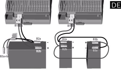
12V-Modus Varianten
Bild 5 12V-Modus mit einer oder zwei Batterien
Der 12V-Modus kann wahlweise mit einer oder zwei Akkus betrieben werden.
Verwenden Sie nur einen Akku (Abbildung 5 - links), schließen Sie diesen mit dem vormontierten Kabelsatz B folgendermaßen an:
1.Den Stecker B1 stecken Sie an die zweite Position von links auf dem Netzteil.
2.Die Stecker B2a (schwarz) kommt auf den Minus-Pol und B2b (rot) auf den Plus-Pol des Akkus.
3.Die Enden B3a und B3b bleiben ungenutzt - durch die vorinstallierte Klemme ist keine zusätzliche Isolierung notwendig und werden durch die Klemme J fixiert.
Bei der Verwendung von zwei Akkus (Abbildung 5 - rechts) verbinden Sie diese wie folgt:
1.Den Stecker B1 stecken Sie an die zweite Position von links auf dem Netzteil.
2.Die Stecker B2a (schwarz) kommt auf den Minus-Pol und B2b (rot) auf den Plus-Pol des Akkus.
3.Die Enden B3a (schwarz) auf den Minus-Pol und B3b (rot) auf den Plus-Pol des zweiten Akkus.
Bosch Sicherheitssysteme GmbH |
F.01U.097.252 | V 3.2 | 2010.01 |
20 de |
AEC-AMC2-UL1 - Installationshandbuch |
|
|
HINWEIS!
Die Einstellung für den 12Voder 24V-Modus erfolgt über einen Schalter am Netzteil. Entfernen Sie zunächst die Spannungsversorgung und stellen Sie den Modus entsprechend der folgenden Darstellung ein.
F.01U.097.252 | V 3.2 | 2010.01 |
Bosch Sicherheitssysteme GmbH |
AEC-AMC2-UL1 - Instrukcja instalacji |
pl 21 |
|
|
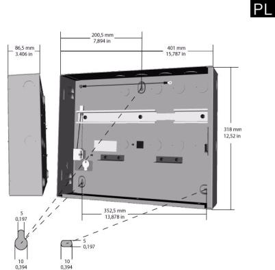
Elementy zestawu
Metalowa obudowa zawiera następujące elementy:
Illustracja 1 Elementy obudowy
1 = Kołek uziemiający pokrywy
2 = Szyna montażowa zasilacza i kontrolera AMC 3 = Kołek uziemiający kontrolera AMC
4 = Nacięcia pod otwory kabli czytników i kabli sygnałowych 5 = Czujnik antysabotażowy pokrywy
6 = Wspornik czujnika temperatury#
7 = Zaciski akumulatora
8 = Główny kołek uziemiający 9 = Tabliczka znamionowa 10 = Naklejka
11 = Nacięcia pod otwór kabla zasilającego 12 = Złącze 3-stykowe
13 = Złącze zasilania
Bosch Sicherheitssyteme GmbH |
F.01U.097.252 | V 3.2 | 2010.01 |
22 pl |
AEC-AMC2-UL1 - Instrukcja instalacji |
|
|
W skład zestawu akcesoriów wchodzą poniższe kable. Należy je zainstalować w sposób opisany na rysunku 1.3, Wymiary obudowy, na stronie 9.
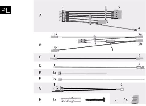
Illustracja 2 Zawartość zestawu akcesoriów
Zawartość zestawu akcesoriów:
A = Gotowy kabel do podłączenia kontrolera AMC do zasilacza B = Gotowy kabel do podłączenia akumulatorów do zasilacza awaryjnego UPS, wchodzącego w skład modułu zasilacza
C = Kabel do trybu 24 V
D = Kabel uziemiający pokrywy
E = Opaski kablowe do zamocowania gotowego kabla G = Gotowy kabel z czujnikiem temperatury
H = Trzy kołki rozporowe S8 z wkrętami do drewna M6 x 50 J = Wspornik do zamocowania kabla
F.01U.097.252 | V 3.2 | 2010.01 |
Bosch Sicherheitssyteme GmbH |
AEC-AMC2-UL1 - Instrukcja instalacji |
pl 23 |
|
|
Montaż obudowy
Otwórz blokadę pokrywy obudowy kluczem znajdującym się w zestawie i zdejmij osłonę z ramy do montażu ściennego.
Ustal położenie obudowy metalowej przy użyciu kołków rozporowych znajdujących się w zestawie.
Za pomocą wkrętów (pozycja H zestawu akcesoriów) zamocuj obudowę do ściany.
Illustracja 3 Wymiary obudowy
Bosch Sicherheitssyteme GmbH |
F.01U.097.252 | V 3.2 | 2010.01 |
24 pl |
AEC-AMC2-UL1 - Instrukcja instalacji |
|
|
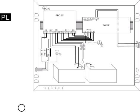
Podłączanie urządzeń
Illustracja 4 Podłączanie urządzeń
|
UWAGA! |
|
|
i |
Poniższa procedura opisuje sposób podłączenia akumulatorów |
||
w trybie 24 V. Informacje na temat połączeń w trybie 12 V |
|||
|
znajdują się w części 1.3, Połączenia w trybie 12 V, strona 15. |
||
|
|
|
|
|
1. |
Zamontuj kontroler AMC na szynie (pozycja na Rysunek 1), |
|
|
|
po lewej stronie zasilacza. |
|
|
2. |
Umieść akumulatory na dole obudowy i . |
|
|
3. |
Zamocuj wspornik J (Rysunek 2) z tyłu obudowy w taki |
|
|
|
sposób, aby można było zamocować nim nieużywane |
|
|
|
złącza kabla B. |
|
|
4. |
Wiązka kabli A: |
|
|
|
a. |
Podłącz wtyk 7-stykowy A1 do złącza zasilania |
|
|
|
kontrolera AMC (oznaczonego napisem POWER). |
|
|
b. |
Podłącz złącze A3 do złącza zasilacza DC i złącze A2 |
|
|
|
do złącza oznaczonego napisem OK. |
|
|
c. |
Podłącz kabel uziemiający A4 poniżej punktu masy . |
|
5. |
Wiązka kabli B: |
|
|
|
a. |
Podłącz wtyk B1 do drugiego złącza od lewej strony |
|
|
|
zasilacza, oznaczonego napisem BAT. |
F.01U.097.252 | V 3.2 | 2010.01 |
Bosch Sicherheitssyteme GmbH |
AEC-AMC2-UL1 - Instrukcja instalacji |
pl 25 |
|
|
b.Podłącz złącze B2b (czerwone) do styku + pierwszego akumulatora.
c.Za pomocą kabla C połącz styk - pierwszego akumulatora ze stykiem + drugiego akumulatora.
d.Podłącz złącze B2a (czarne) do styku - drugiego akumulatora.
e.Złącza B3a i B3b są nieużywane.
6.Wiązka kabli G:
a.Podłącz złącze G1 do złącza zasilacza oznaczonego napisem RTH.
b.Przeprowadź kabel przez wspornik czujnika temperatury w taki sposób, aby czujnik temperatury G2 zwisał na wysokości około 5 cm nad akumulatorami.
7.Gotowa wiązka kabli 12:
a.Podłącz wtyk 2-stykowy 13 do złącza AC zasilacza.
8.Gotowa wiązka kabli :
a.Podłącz swobodne końce kabla czujnika antysabotażowego pokrywy do 2-stykowego złącza śrubowego u góry kontrolera AMC. Umieść kabel w szczelinie między obudową a szyną montażową.
NIEBEZPIECZENSTWO!
Przed ostatecznym podłączeniem zasilania wyjmij bezpiecznik ze złącza 3-stykowego .
Nie zakładaj bezpiecznika do czasu zakończenia procedury instalacji.
9.Podłącz główne złącze zasilania sieciowego X:
a.Podłącz brązowy przewód (faza) do zacisku L1.
b.Podłącz niebieski przewód (zero) do zacisku N.
c.Podłącz kabel uziemiający do obudowy w pozycji 11.
UWAGA!
Przytnij przewody zasilania zewnętrznego w taki sposób, aby przewód uziemiający (żółto-zielony) był o co najmniej 20 mm
!dłuższy od przewodów napięciowych (niebieski i brązowy). Dzięki temu przewód uziemiający nie zostanie odłączony przed przewodami napięciowymi przy przypadkowym pociągnięciu za kabel.
Czytniki i inne urządzenia peryferyjne należy podłączyć w sposób opisany w instrukcji instalacji kontrolera AMC. Kable urządzeń należy przeprowadzić przez otwory w górnej i prawej ściance obudowy lub z tyłu obudowy.
Bosch Sicherheitssyteme GmbH |
F.01U.097.252 | V 3.2 | 2010.01 |

26 pl |
AEC-AMC2-UL1 - Instrukcja instalacji |
|
|
10.Kabel D:
a.Podłącz wtyk D1 do kołka uziemiającego 1.
b.Podłącz wtyk D2 do kołka uziemiającego pokrywy.
11.Załóż bezpiecznik.
12.Zamknij pokrywę.
F.01U.097.252 | V 3.2 | 2010.01 |
Bosch Sicherheitssyteme GmbH |
AEC-AMC2-UL1 - Instrukcja instalacji |
pl 27 |
|
|
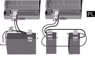
Połączenia w trybie 12 V
Illustracja 5 Trybie 12 V
Tryb 12 V można skonfigurować przy użyciu jednego lub dwóch akumulatorów. W przypadku instalacji z jednym akumulatorem należy skorzystać z rysunku 5 - po lewej stronie, i wykonać następującą procedurę:
1.Podłącz złącze B1 do złącza zasilania oznaczonego napisem BAT.
2.Podłącz złącze B2a (czarne) do zacisku - akumulatora, a złącze B2b (czerwone) do zacisku + akumulatora.
3.Złącza B3a i B3b są nieużywane — zamocuj je za pomocą wspornika J.
W przypadku instalacji z dwoma akumulatorami należy skorzystać z rysunku 5 - po prawej stronie, i wykonać następującą procedurę:
1.Podłącz złącze B1 do złącza zasilania oznaczonego napisem BAT.
2.Podłącz złącze B2a (czarne) do zacisku - akumulatora, a złącze B2b (czerwone) do zacisku + akumulatora.
3.Podłącz złącze B3a (czarne) do zacisku - drugiego akumulatora, a złącze B3b (czerwone) do zacisku + drugiego akumulatora.
Bosch Sicherheitssyteme GmbH |
F.01U.097.252 | V 3.2 | 2010.01 |
Loading...