


P6-P8H61E
Table of contents
 Loading...
P6-P8H61E
ASUS PC (Desktop Barebone)
User’s Manual

ii
E6509
First Edition V1
March 2011
Copyright © 2011 ASUSTeK Computer Inc. All Rights Reserved.
No part of this manual, including the products and software described in it, may be reproduced,
transmitted, transcribed, stored in a retrieval system, or translated into any language in any form or by any
means, except documentation kept by the purchaser for backup purposes, without the express written
permission of ASUSTeK Computer Inc. (“ASUS”).
Product warranty or service will not be extended if: (1) the product is repaired, modied or altered, unless
such repair, modication of alteration is authorized in writing by ASUS; or (2) the serial number of the
product is defaced or missing.
ASUS PROVIDES THIS MANUAL “AS IS” WITHOUT WARRANTY OF ANY KIND, EITHER EXPRESS
OR IMPLIED, INCLUDING BUT NOT LIMITED TO THE IMPLIED WARRANTIES OR CONDITIONS OF
MERCHANTABILITY OR FITNESS FOR A PARTICULAR PURPOSE. IN NO EVENT SHALL ASUS, ITS
DIRECTORS, OFFICERS, EMPLOYEES OR AGENTS BE LIABLE FOR ANY INDIRECT, SPECIAL,
INCIDENTAL, OR CONSEQUENTIAL DAMAGES (INCLUDING DAMAGES FOR LOSS OF PROFITS,
LOSS OF BUSINESS, LOSS OF USE OR DATA, INTERRUPTION OF BUSINESS AND THE LIKE),
EVEN IF ASUS HAS BEEN ADVISED OF THE POSSIBILITY OF SUCH DAMAGES ARISING FROM ANY
DEFECT OR ERROR IN THIS MANUAL OR PRODUCT.
SPECIFICATIONS AND INFORMATION CONTAINED IN THIS MANUAL ARE FURNISHED FOR
INFORMATIONAL USE ONLY, AND ARE SUBJECT TO CHANGE AT ANY TIME WITHOUT NOTICE,
AND SHOULD NOT BE CONSTRUED AS A COMMITMENT BY ASUS. ASUS ASSUMES NO
RESPONSIBILITY OR LIABILITY FOR ANY ERRORS OR INACCURACIES THAT MAY APPEAR IN THIS
MANUAL, INCLUDING THE PRODUCTS AND SOFTWARE DESCRIBED IN IT.
Products and corporate names appearing in this manual may or may not be registered trademarks or
copyrights of their respective companies, and are used only for identication or explanation and to the
owners’ benet, without intent to infringe.
Offer to Provide Source Code of Certain Software
This product may contain copyrighted software that is licensed under the General Public License (“GPL”)
and under the Lesser General Public License Version (“LGPL”). The GPL and LGPL licensed code in this
product is distributed without any warranty. Copies of these licenses are included in this product.
You may obtain the complete corresponding source code (as dened in the GPL) for the GPL Software,
and/or the complete corresponding source code of the LGPL Software (with the complete machinereadable “work that uses the Library”) for a period of three years after our last shipment of the product
including the GPL Software and/or LGPL Software, which will be no earlier than December 1, 2011, either
(1) for free by downloading it from http://support.asus.com/download;
or
(2) for the cost of reproduction and shipment, which is dependent on the preferred carrier and the location
where you want to have it shipped to, by sending a request to:
ASUSTeK Computer Inc.
Legal Compliance Dept.
15 Li Te Rd.,
Beitou, Taipei 112
Taiwan
In your request please provide the name, model number and version, as stated in the About Box of the
product for which you wish to obtain the corresponding source code and your contact details so that we
can coordinate the terms and cost of shipment with you.
The source code will be distributed WITHOUT ANY WARRANTY and licensed under the same license as
the corresponding binary/object code.
This offer is valid to anyone in receipt of this information.
ASUSTeK is eager to duly provide complete source code as required under various Free Open Source
Software licenses. If however you encounter any problems in obtaining the full corresponding source code
we would be much obliged if you give us a notication to the email address gpl@asus.com, stating the
product and describing the problem (please do NOT send large attachments such as source code archives
etc to this email address).

iii
Table of contents
Notices ...........................................................................................................v
Safety information ..........................................................................................vi
About this guide ............................................................................................ vii
System package contents ............................................................................ viii
Chapter 1: System introduction
1.1 Welcome! ....................................................................................... 1-2
1.2 Front panel ....................................................................................
1-2
1.3 Rear panel ......................................................................................
1-4
1.4 Internal components .......................................................................
1-6
1.5 Qualied Vendors Lists (QVL) ........................................................
1-7
Chapter 2: Starting up
2.1 Installing an operating system ........................................................ 2-2
2.2 Powering up ...................................................................................
2-2
2.3 Support DVD information ...............................................................
2-2
2.3.1 Running the support DVD ...............................................
2-3
2.3.2 Utilities menu ..................................................................
2-4
2.3.3 Make Disk menu .............................................................
2-5
2.3.4 Manual menu ..................................................................
2-5
2.3.5 ASUS Contact information ..............................................
2-6
2.3.6 Other information ............................................................
2-6
2.4 Software information ......................................................................
2-8
2.4.1 AI Suite II ........................................................................
2-8
2.4.2 ASUS AI Manager .........................................................
2-17
Chapter 3: Motherboard info
3.1 Introduction .................................................................................... 3-2
3.2 Motherboard layout ........................................................................
3-2
3.3 Jumpers .........................................................................................
3-3
3.4 Connectors .....................................................................................
3-4
Chapter 4: BIOS setup
4.1 Managing and updating your BIOS ................................................ 4-2
4.1.1 ASUS Update utility ........................................................
4-2
4.1.2 ASUS EZ Flash 2 ............................................................
4-4
4.1.3 ASUS CrashFree BIOS 3 ................................................
4-5
4.1.4 ASUS BIOS Updater .......................................................
4-6

iv
Table of contents
4.2 BIOS setup program ...................................................................... 4-9
BIOS menu screen ......................................................................... 4-9
4.3 Main menu ...................................................................................
4-13
4.3.1 System Language [English] ..........................................
4-13
4.3.2 System Date [Day xx/xx/xxxx] .......................................
4-13
4.3.3 System Time [xx:xx:xx] .................................................
4-13
4.3.4 Security .........................................................................
4-13
4.4 Advanced menu ...........................................................................
4-15
4.4.1 CPU Conguration ........................................................
4-15
4.4.2 System Agent Conguration .........................................
4-16
4.4.3 PCH Conguration ........................................................
4-17
4.4.4 SATA Conguration .......................................................
4-17
4.4.5 USB Conguration ........................................................
4-18
4.4.6 Onboard Devices Conguration ....................................
4-18
4.4.7 APM ..............................................................................
4-19
4.5 Monitor menu ...............................................................................
4-19
4.5.1 CPU Temperature / MB Temperature
[xxxºC/xxxºF] ...... 4-20
4.5.2 CPU / Chassis / Power Fan Speed [xxxx RPM]
or [Ignore] / [N/A] ...........................................................
4-20
4.5.3 CPU Q-Fan Control [Enabled] ......................................
4-20
4.5.4 Chassis Q-Fan Control [Enabled] .................................
4-20
4.5.5 CPU Voltage, 3.3V Voltage, 5V Voltage, 12V Voltage ..
4-20
4.6 Boot menu ....................................................................................
4-21
4.6.1 Bootup NumLock State [On] .........................................
4-21
4.6.2 Full Screen Logo [Enabled] ...........................................
4-21
4.6.3 Wait for ‘F1’ if Error [Enabled] .......................................
4-21
4.6.4 Option ROM Messages [Force BIOS] ...........................
4-21
4.6.5 Setup Mode [EZ Mode] .................................................
4-22
4.6.6 Boot Option Priorities ....................................................
4-22
4.6.7 Boot Override ................................................................
4-22
4.7 Tools menu ...................................................................................
4-23
4.7.1 ASUS EZ Flash 2 ..........................................................
4-23
4.7.2 ASUS SPD Information .................................................
4-23
4.8 Exit menu .....................................................................................
4-24
ASUS contact information ......................................................................... 4-25

v
Notices
Canadian Department of Communications Statement
This digital apparatus does not exceed the Class B limits for radio noise emissions from
digital apparatus set out in the Radio Interference Regulations of the Canadian Department
of Communications.
This class B digital apparatus complies with Canadian ICES-003.
WARNING! The use of shielded cables for connection of the monitor to the graphics card
is required to assure compliance with FCC regulations. Changes or modications to this
unit not expressly approved by the party responsible for compliance could void the user’s
authority to operate this equipment.
ASUS Recycling/Takeback Services
ASUS recycling and takeback programs come from our commitment to the highest standards
for protecting our environment. We believe in providing solutions for you to be able to
responsibly recycle our products, batteries, other components, as well as the packaging
materials. Please go to http://csr.asus.com/english/Takeback.htm for the detailed recycling
information in different regions.
REACH
Complying with the REACH (Registration, Evaluation, Authorisation, and Restriction of
Chemicals) regulatory framework, we published the chemical substances in our products at
ASUS REACH website at http://csr.asus.com/english/REACH.htm
Federal Communications Commission Statement
This device complies with Part 15 of the FCC Rules. Operation is subject to the following two
conditions:
•
This device may not cause harmful interference, and
•
This device must accept any interference received including interference that may
cause undesired operation.
This equipment has been tested and found to comply with the limits for a Class B digital
device, pursuant to Part 15 of the FCC Rules. These limits are designed to provide
reasonable protection against harmful interference in a residential installation. This
equipment generates, uses and can radiate radio frequency energy and, if not installed
and used in accordance with manufacturer’s instructions, may cause harmful interference
to radio communications. However, there is no guarantee that interference will not occur
in a particular installation. If this equipment does cause harmful interference to radio or
television reception, which can be determined by turning the equipment off and on, the user
is encouraged to try to correct the interference by one or more of the following measures:
•
Reorient or relocate the receiving antenna.
•
Increase the separation between the equipment and receiver.
•
Connect the equipment to an outlet on a circuit different from that to which the receiver
is connected.
•
Consult the dealer or an experienced radio/TV technician for help.

vi
Safety information
Electrical safety
• To prevent electric shock hazard, disconnect the power cable from the electric outlet
before relocating the system.
• When adding or removing devices to or from the system, ensure that the power cables
for the devices are unplugged before the signal cables are connected. If possible,
disconnect all power cables from the existing system before you add a device.
• Before connecting or removing signal cables from the motherboard, ensure that all
power cables are unplugged.
• Seek professional assistance before using an adapter or extension cord. These
devices could interrupt the grounding circuit.
• Ensure that your power supply is set to the correct voltage in your area. If you are not
sure about the voltage of the electrical outlet you are using, contact your local power
company.
• If the power supply is broken, do not try to x it by yourself. Contact a qualied service
technician or your retailer.
Operation safety
•
Before installing the motherboard and adding devices on it, carefully read all the
manuals that came with the package.
•
Before using the product, ensure that all cables are correctly connected and the power
cables are not damaged. If you detect any damage, contact your dealer immediately.
•
To avoid short circuits, keep paper clips, screws, and staples away from connectors,
slots, sockets and circuitry.
•
Avoid dust, humidity, and temperature extremes. Do not place the product in any area
where it may become wet.
•
Place the product on a stable surface.
•
If you encounter technical problems with the product, contact a qualied service
technician or your retailer.
Lithium-Ion Battery Warning
CAUTION: Danger of explosion if battery is incorrectly replaced. Replace only with the
same or equivalent type recommended by the manufacturer. Dispose of used batteries
according to the manufacturer’s instructions.
VORSICHT: Explosionsgetahr bei unsachgemäßen Austausch der Batterie. Ersatz nur
durch denselben oder einem vom Hersteller empfohlenem ähnljchen Typ. Entsorgung
gebrauchter Batterien nach Angaben des Herstellers.
LASER PRODUCT WARNING
CLASS 1 LASER PRODUCT
vii
Conventions used in this guide
WARNING: Information to prevent injury to yourself when trying to complete a
task.
CAUTION: Information to prevent damage to the components when trying to
complete a task.
IMPORTANT: Instructions that you MUST follow to complete a task.
NOTE: Tips and additional information to aid in completing a task.
Where to nd more information
Refer to the following sources for additional information and for product and software
updates.
1. ASUS Websites
The ASUS websites worldwide provide updated information on ASUS hardware and
software products. Refer to the ASUS contact information.
2. Optional Documentation
Your product package may include optional documentation, such as warranty yers,
that may have been added by your dealer. These documents are not part of the
standard package.
About this guide
Audience
This guide provides general information and installation instructions about the ASUS Vintage
V-Series P8H61E barebone system. This guide is intended for experienced users and
integrators with hardware knowledge of personal computers.
How this guide is organized
This guide contains the following parts:
1. Chapter 1: System introduction
This chapter gives a general description of the ASUS
V-Series P8H61E. The chapter lists the system features, including introduction on the
front and rear panel, and internal components.
2. Chapter 2: Starting up
This chapter helps you power up the system and install drivers and utilities from the
support DVD.
3. Chapter 3: Motherboard info
This chapter gives information about the motherboard that comes with the system. This
chapter includes the motherboard layout, jumper settings, and connector locations.
4. Chapter 4: BIOS setup
This chapter tells how to change system settings through the BIOS Setup menus and
describes the BIOS parameters.
viii
System package contents
Check your P6-P8H61E system package for the following items.
If any of the items is damaged or missing, contact your retailer immediately.
Item description
1. ASUS P6-P8H61E barebone system with
• ASUS motherboatd
• Power supply unit
• ASUS chassis
• CPU cooler
2. Cable
• AC power cable
3. Support DVD
4. Quick Installation Guide
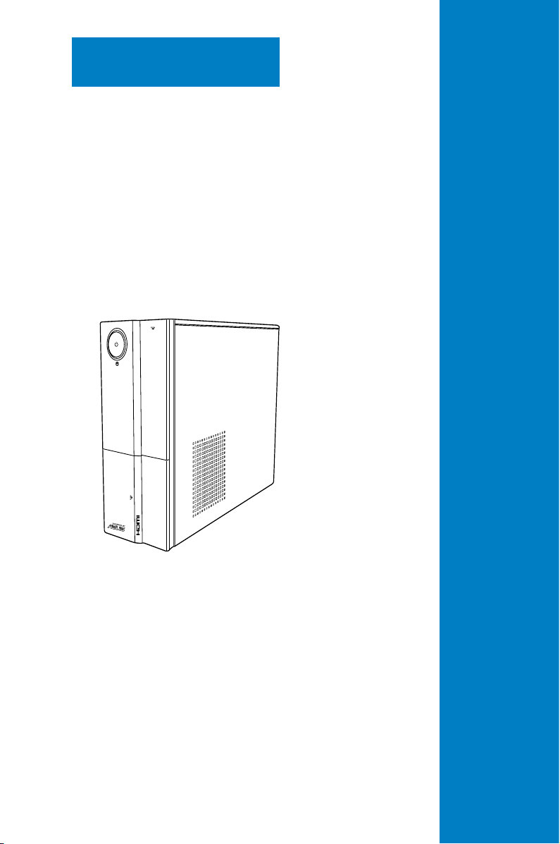
System introduction
This chapter gives a general description of
the ASUS P6-P8H61E. The chapter lists
the system features including introduction
on the front and rear panel, and internal
components.
Chapter 1
1-2
Chapter 1: System introduction
1.1 Welcome!
Thank you for choosing the ASUS P6-P8H61E!
The ASUS P6-P8H61E is an all-in-one barebone system with a versatile home entertainment
feature.
The system comes in a stylish casing and powered by the ASUS motherboard that supports
the Intel® Lynneld/Clarkdale Dual-Core / Quad-Core processors in the 1156-land package.
The system supports up to 8 GB of system memory using DDR3 DIMMs. High-resolution
graphics via integrated graphics controller or PCI Express x16 slot, Serial ATA, USB 2.0, and
8-channel audio feature the system and take you ahead in the world of power computing.
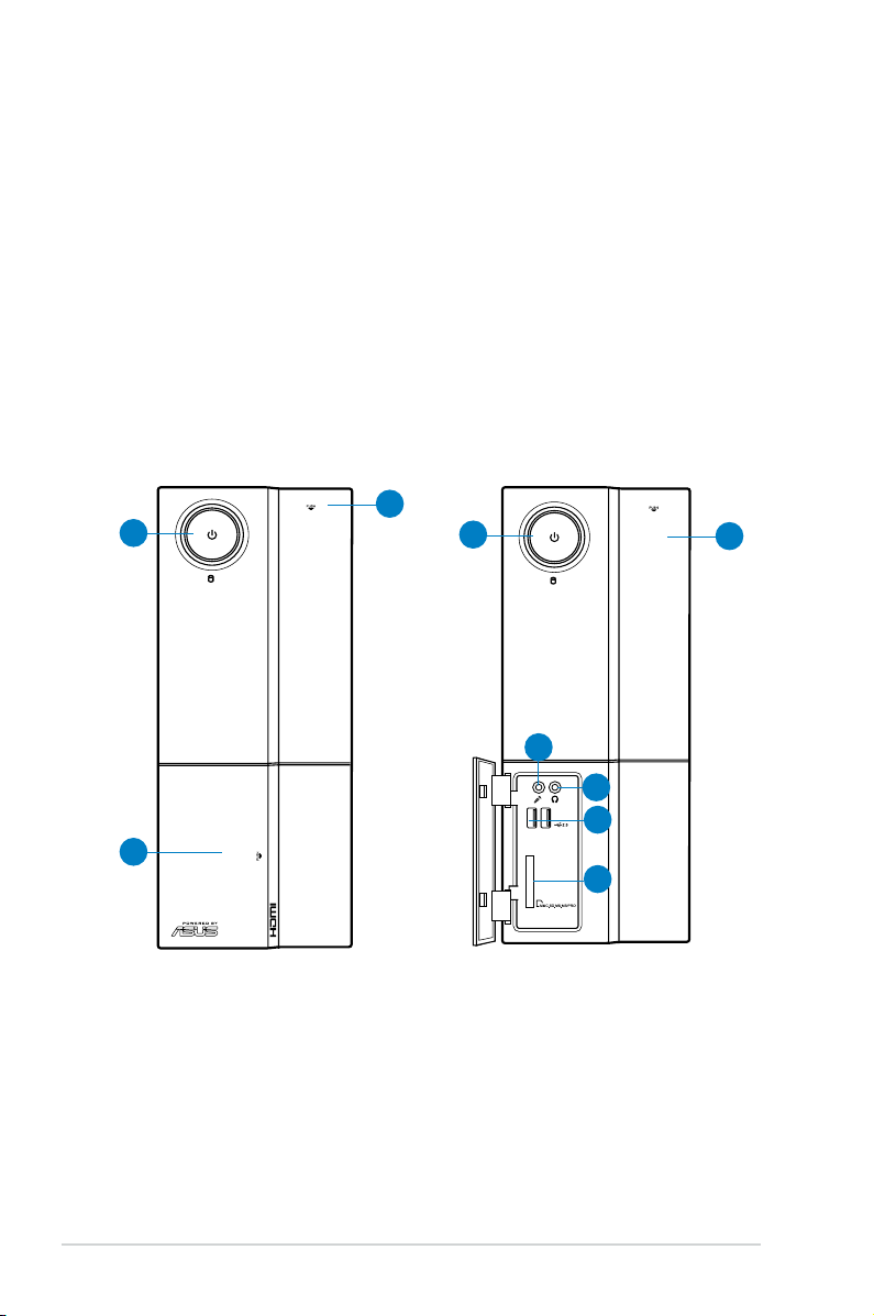
1.2 Front panel
The front panel includes the optical drive bays, power button, and several I/O ports are
located at the front panel.
1
2
3
1
4
3
5
6
7

1-3ASUS P6-P8H61E
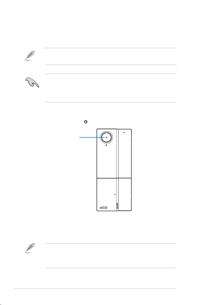
1. Power button. Press this button to turn the system on.
2. Front panel cover. Push to open the front panel cover.
3. Optical disk drive cover. Push to eject the optical disk drive.
4. Microphone port. This Mic (pink) port connects a microphone.
5. Headphone port. This Line out (lime) port connects a headphone with a stereo mini-
plug.
6. USB 3.0 ports. These Universal Serial Bus 3.0 (USB 3.0) ports are available for
connecting USB 3.0 devices such as a mouse, printer, scanner, camera, PDA, and
others.
7. Multimedia Card / Secure Digital™ / MemoryStick® / Memory Stick Pro™ card
slot.
1-4
Chapter 1: System introduction
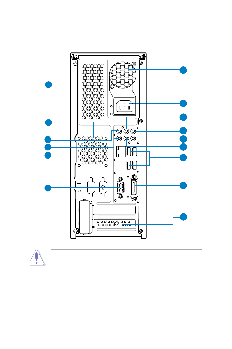
1.3 Rear panel
The system rear panel includes the power connector and several I/O ports that allow
convenient connection of devices.
1. Chassis air vent
. The vent is for ventilation inside the system chassis.
2. Power supply unit fan vent. This vent is for the PSU fan that provides ventilation
inside the power supply unit.
3. Chassis fan vent. This vent is for the fan that provides ventilation inside the system
chassis.
4. Power connector. This connector is for the power cable and plug.
1
Do NOT cover the rear vent , and the ambient temperature is limited up to 35oC to prevent
the system from overheating.
5
10
11
13
3
15
14
12
9
8
7
6
4
2
1-5ASUS P6-P8H61E
5. Line In port (light blue). This port connects the tape, CD, DVD player, or other audio
sources.
6. Line Out port (lime). This port connects a headphone or a speaker. In 4-channel, 6-
channel, and 8-channel conguration, the function of this port becomes Front Speaker
Out.
7. Microphone port (pink). This port connects a microphone.
8. Side Speaker Out port (gray). This port connects the side speaker in an 8-channel
audio conguration.
9. Rear Speaker Out port (black). This port connects the rear speakers in a 4-channel,
6-channel, or 8-channel audio conguration.
10. Center / Subwoofer port (orange). This port connects the center/subwoofer speakers.
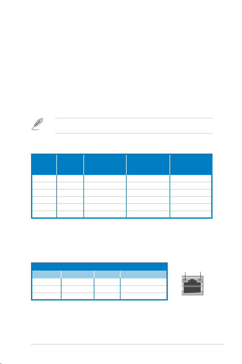
Activity/Link Speed LED
Status Description Status Description
OFF No link OFF 10 Mbps connection
ORANGE Linked ORANGE 100 Mbps connection
BLINKING Data activity GREEN 1 Gbps connection
LAN port LED indications
SPEED
LED
ACT/LINK
LED
LAN port
11. LAN (RJ-45) port. This port allows gigabit connection to a Local Area Network (LAN)
through a network hub. Refer to the table below for the LAN port LED indications.
Refer to the audio conguration table below for the function of the audio ports in 2, 4, 6, or
8-channel conguration.
Audio 2, 4, 6, or 8-channel conguration
Port
Headset
2channel
4-channel 6-channel 8-channel
Light Blue Line In Line In Line In Line In
Lime Line Out Front Speaker Out Front Speaker Out Front Speaker Out
Pink Mic In Mic In Mic In Mic In
Orange – – Center/Subwoofer Center/Subwoofer
Black – Rear Speaker Out Rear Speaker Out Rear Speaker Out
Gray – – – Side Speaker Out
1-6
Chapter 1: System introduction
12. USB 2.0 ports 1 ~ 4. These 4-pin Universal Serial Bus (USB) ports are available for
connecting USB 2.0 devices.
13. Video Graphics Adapter (VGA) port
. This 15-pin port is for a VGA monitor or other
VGA-compatible devices.
14. HDMI port
. This is a High-Denition Mulltimedia Interface (HDMI) connector, and is
HDCP compliant allowing playback of HD DVD, Blu-Rau discs, and other protected
content.
15. Expansion slot covers
. Remove these covers when installing expansion cards.
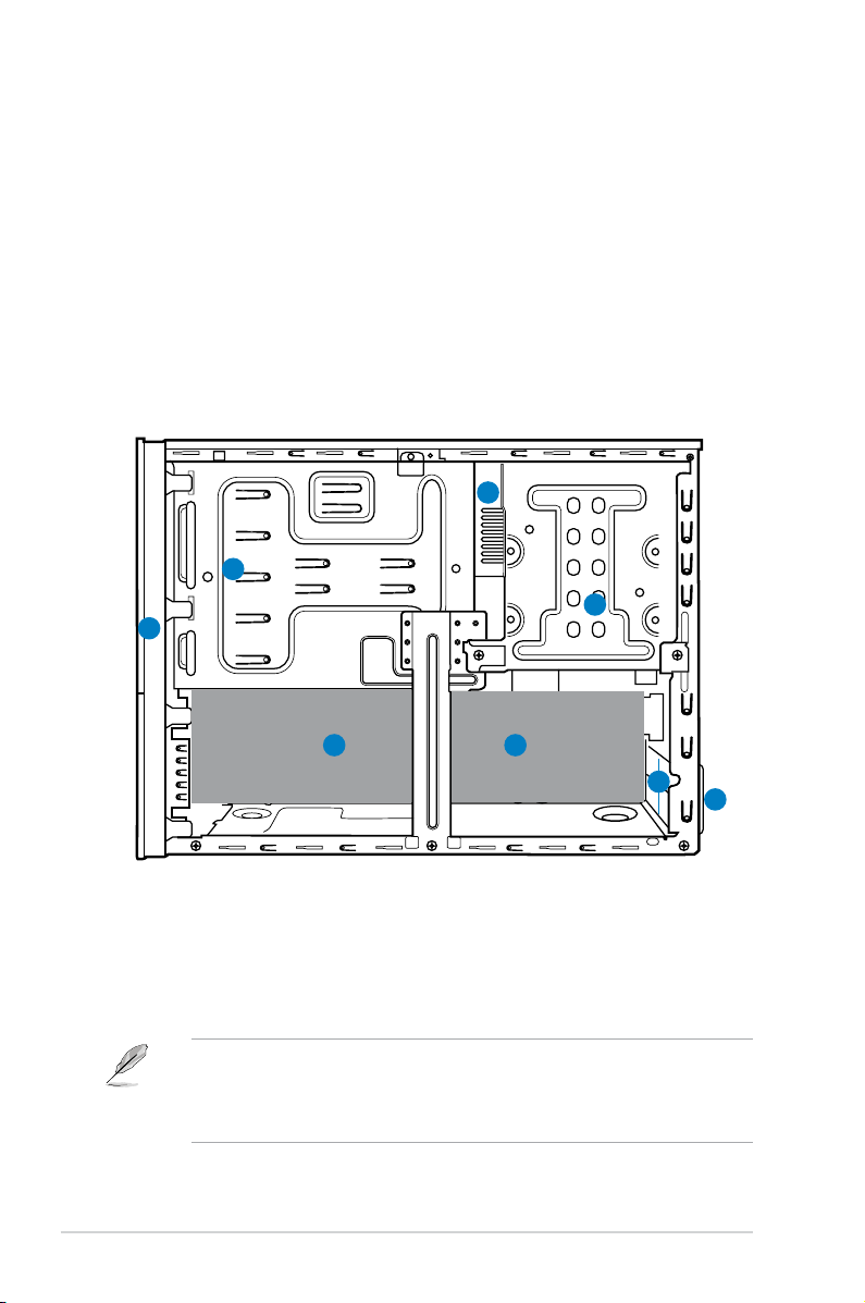
1.4 Internal components
The illustration below is the internal view of the system when you remove the side cover and
the power supply unit. The installed components are labeled for your reference.
• Refer to the bundled Quick Installation Guide for installing additional system
components and get assistance from professionals when you disassemble or
assemble the system.
• Refer to the Chapter 4 in this user guide for motherboard details.
1. Front panel cover
2. 5.25-inch optical drive bays
3. Hard disk drive bay
4. Power supply unit (under the HDD bay)
5. ASUS motherboard
6. Expansion slot metal brackets
7. Metal bracket lock
1
3
4
5
2
6
5
7
1-7ASUS P6-P8H61E
1.5 Qualied Vendors Lists (QVL)
DDR3-1333 MHz capability
continued on the next page
Vendors Part No. Size
SS/DSChip
Brand
Chip No. Timing Voltage
DIMM
socket
support
(Optional)
A B
A-Data AD31333001GOU 1GB SS A-Data AD30908C8D-151C
E0906
- - • •
A-Data AD31333G001GOU 3GB
(3 x 1GB)
SS - - 8-8-8-24 1.65-1.85V • •
Apacer 78.A1GC6.9L1 2GB DS APACER AM5D5808DEWSBG - - • •
Apacer 78.A1GC6.9L1 2GB DS Apacer AM5D5808FEQSBG 9 - • •
CORSAIR TW3X4G1333C9D G 4GB
(2 x 2GB)
DS - - 9-9-9-24 1.50V • •
CORSAIR CMX8GX3M4A1333C9 8GB
(4 x 2GB)
DS - - 9-9-9-24 1.50V • •
Crucial CT25664BA1339.16FF 2GB DS Micron 9KF27D9KPT 9 - • •
Crucial BL25664BN1337.16FF
(XMP)
6GB
(3 x 2GB)
DS - - 7-7-7-24 1.65V • •
G.SKILL F3-10600CL8D-
2GBHK(XMP)
1GB SS G.SKILL - - - • •
G.SKILL F3-10666CL7T-
3GBPK(XMP)
3GB
(3 x 1GB)
SS - - 7-7-7-18 1.5~1.6V • •
G.SKILL F3-10666CL8D-
4GBECO(XMP)
4GB
(2 x 2GB)
DS - - 8-8-8-8-24 XMP
1.35V
• •
G.SKILL F3-10666CL7D-
8GBRH(XMP)
8GB
(2 x 4GB)
DS - - 7-7-7-21 1.5V • •
GEIL GV32GB1333C9DC 2GB
(2 x 1GB)
DS - - 9-9-9-24 1.5V • •
GEIL GV34GB1333C9DC 4GB
(2 x 2GB)
DS - - 9-9-9-24 1.5V • •
Hynix HMT125U6TFR8A-H9 2GB DS HYNIX H5TC1G83TFRH9A - 1.35V
(low
voltage)
• •
HYNIX HMT351U6BFR8C-H9 4GB DS HYNIX H5TQ2G83BFRH9C - - • •
KINGMAX FLFE85F-C8KM9 NAES 2GB SS KINGMAX KFC8FNMXF-
BXX-15A
- - • •
KINGMAX FLFE85F-B8KL9 NEES 2GB DS KINGMAX KKB8FNWBFGNX-
26A
- - • •
KINGMAX FLFF65F-C8KM9 NEES 4GB DS KINGMAX KFC8FNMXF-
BXX-15A
- - • •
Kingston KVR1333D3N9/2G 2GB DS ELPIDA J1108BDSE-DJ-F 9 1.5V • •
Kingston KHX1333C9D3UK2/
4GX(XMP)
4GB
(2 x 2GB)
DS - - 9 XMP
1.25V
• •
KINGSTON KVR1333D3N9/4G 4GB DS HYNIX H5TQ2G83AFRH9C 9 1.5V • •
KINGSTON KVR1333D3N9/4G 4GB DS Hynix H5TQ2G83AFR - - • •
MICRON MT8JTF25664AZ-1G4D1 2GB SS MICRON OJD12D9LGK - - • •
1-8
Chapter 1: System introduction
DDR3-1333 MHz capability
Vendors Part No. Size SS/DSChip
Brand
Chip No. Timing Voltage DIMM
socket
support
(Optional)
A B
OCZ OCZ3F13334GK 4GB
(2 x 2GB)
DS - - 9-9-9-20 1.7V • •
OCZ OCZ3X1333LV6GK(XMP) 6GB(3 x
2GB)
DS - - 8-8-8-20 1.60V • •
PSC AL8F8G73D-DG1 2GB DS PSC A3P1GF3DGF 8-8-8-24 1.5V • •
SAMSUNG M378B5673FH0-CH9 2GB DS SAMSUNG K4B1G0846F - - • •
Super Talent W1333UA1GH 1GB SS HYNIX H5TQ1G83TFR 9 - • •
Super Talent W1333X2G8(XMP) 1GB SS - - 8 - • •
Transcend TS256MLK64V3U 2GB DS Micron 9GF27D9KPT - - • •
DDR3-1066 MHz capability
SS - Single-sided / DS - Double-sided
DIMM support:
• A*: Supports one module inserted in any slot as Single-channel
memory conguration.
• B*: Supports one pair of modules inserted into both slots as
one pair of Dual-channel memory conguration.
Visit the ASUS website at www.asus.com for the latest QVLs.
Vendors Part No. Size
SS/DSChip
Brand
Chip No. Timing Voltage
DIMM
socket
support
(Optional)
A B
ELPIDA EBJ21UE8EDF0-
AE-F
2GB DS ELPIDA J1108EDSE-DJ-F - 1.35V
(low
voltage)
• •
KINGSTON KVR1066D3N7/1G 1GB SS KTC D1288JPNDPLD9U 7 1.5V • •
KINGSTON KVR1066D3N7/4G 4GB DS Hynix H5TQ2G83AFR 7 1.5V • •
Micron MT8JTF12864AZ-
1G1F1
1GB SS Micron 9GF22D9KPT 7 - • •
OCZ OCZ3G1066LV4GK 4GB
(2 x 2GB)
DS Micron 9BF27D9KPV 7-7-7-20 1.65V • •

This chapter helps you power up the system
and install drivers and utilities from the
support DVD.
Chapter 2
Starting up
2-2
Chapter 2: Starting up
2.1 Installing an operating system
The barebone system supports Windows® XP/Vista/7 operating systems (OS). Always install
the latest OS version and corresponding updates so you can maximize the features of your
hardware.
2.3 Support DVD information
The support DVD that came with the system contains useful software and several utility
drivers that enhance the system features.
2.2 Powering up
Press the system power button ( ) to enter the OS.
Motherboard settings and hardware options vary. Use the setup procedures presented
in this chapter for general reference only. Refer to your OS documentation for more
information.
• Screen display and driver options may not be the same for different operating system
versions.
• The contents of the support DVD are subject to change at any time without notice.
Visit the ASUS website at www.asus.com for updates.
• Windows XP OS setup cannot recognize Serial ATA hard drives in a RAID set without
the necessary drivers. Use a RAID driver disk when installing Windows XP OS to a
Serial ATA hard drive included in a RAID set.
• From the Windows XP setup screen, press F6 when prompted then follow succeeding
screen instructions to install the SATA drivers.
Press to turn ON the system
2-3
ASUS P6-P8H61E
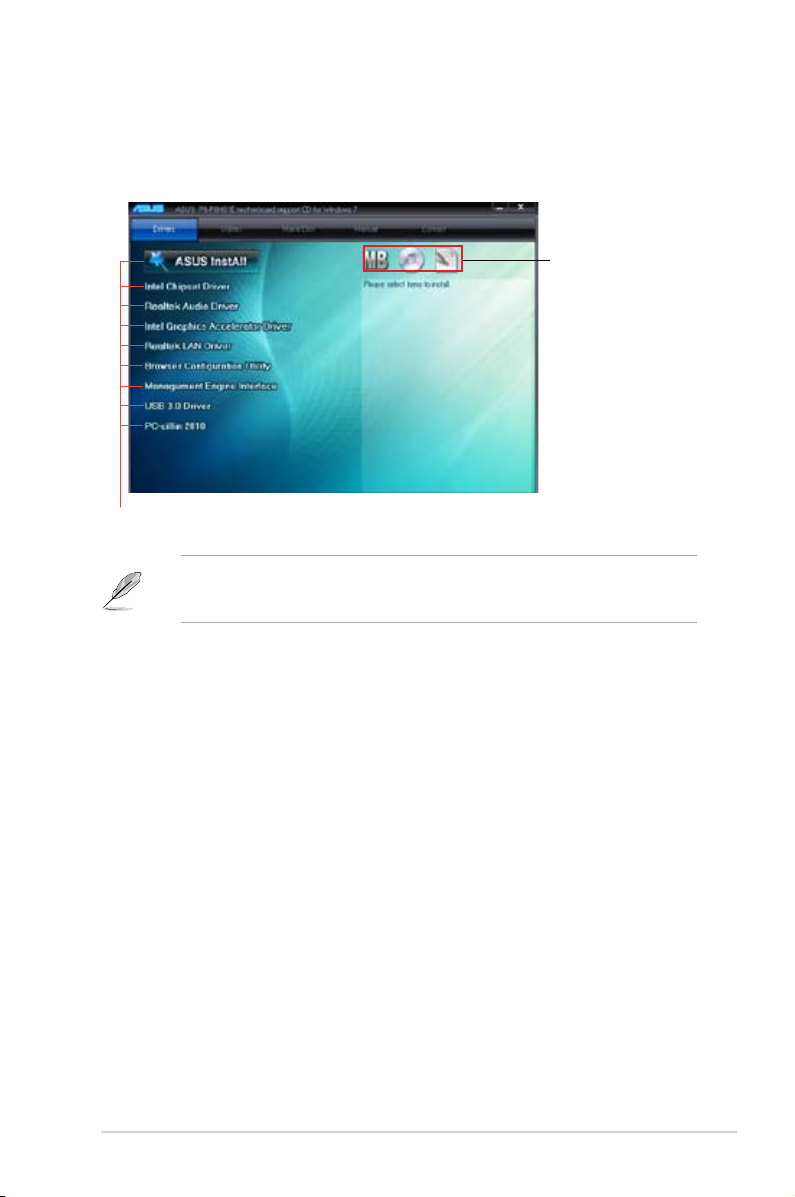
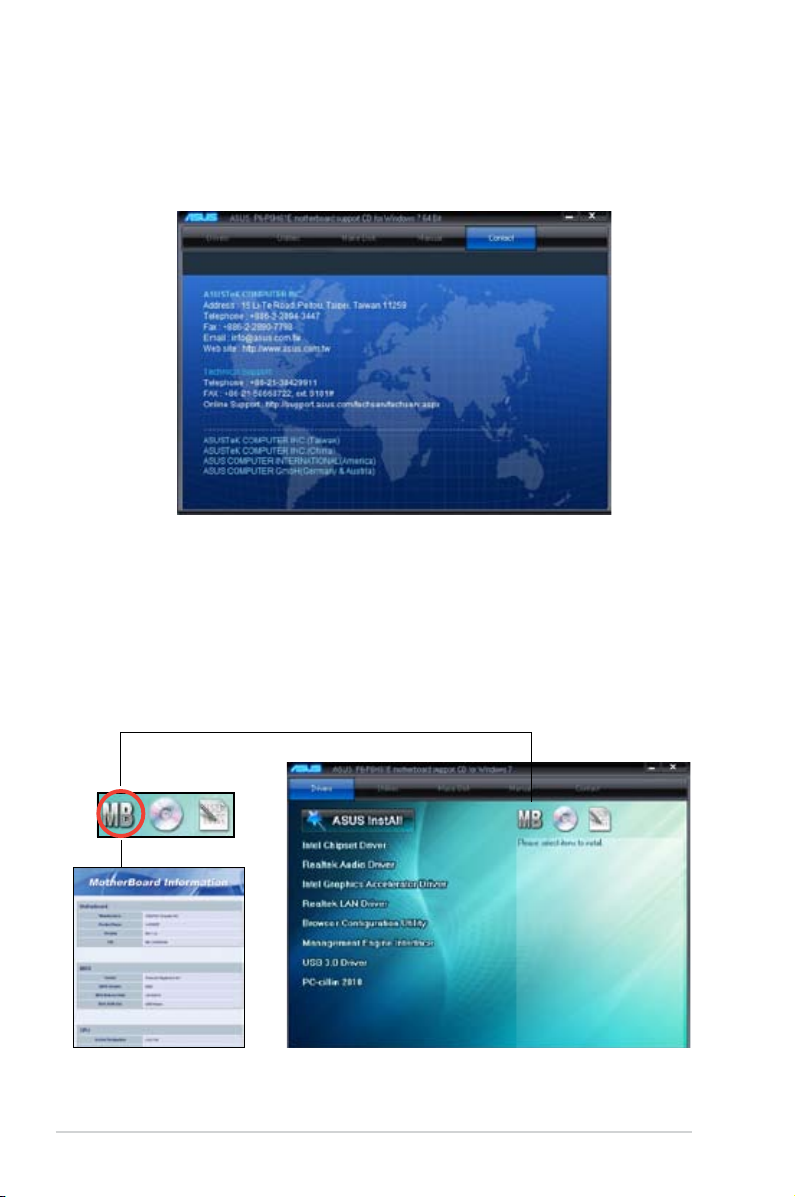
2.3.1 Running the support DVD
To begin using the support DVD, place the DVD in your optical drive. The DVD automatically
displays the Drivers menu if Autorun is enabled in your computer.
If Autorun is NOT enabled in your computer, browse the contents of the support DVD to
locate the le ASSETUP.EXE from the BIN folder. Double-click the ASSETUP.EXE to run
the DVD.
ASUS InstAll
Launches the ASUS InstAll driver installation wizard.
Reaktek Audio Driver
Installs the Realtek audio driver and application.
Intel Graphics Accelerator Driver
Installs the Intel® Graphics Accelerator Driver.
Browser Conguration Utility
Installs the Browser Conguration Utility.
Management Engine Interface
Installs the Management Engine Interface.
USB 3.0 Driver
Installs the USB 3.0 driver.
PC-cillin 2010
Installs the PC-cillin 2010 utility.
Click an item to install
Click an icon to
display support
DVD/motherboard
information
2-4
Chapter 2: Starting up
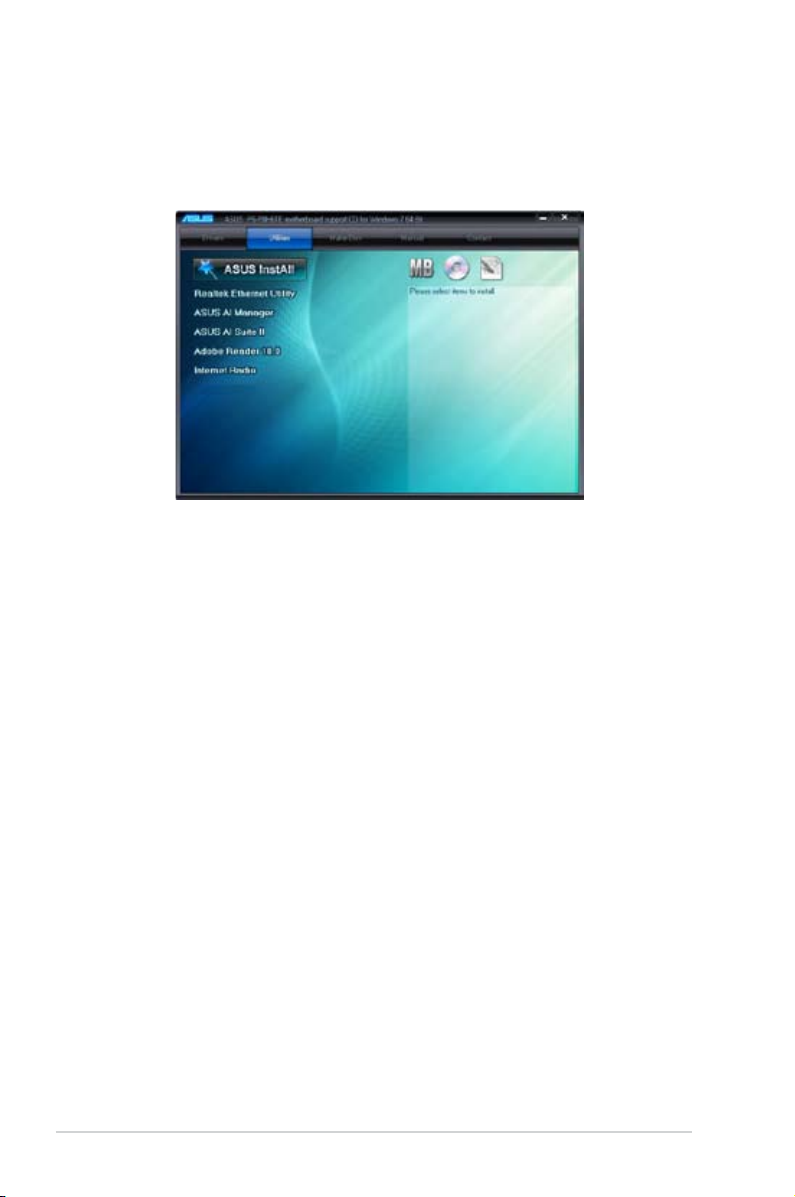
2.3.2 Utilities menu
The Utilities menu shows the applications and other software that the motherboard supports.
ASUS InstAll
Installs all the utilities through the Installation Wizard.
Realtek Ethernet Utility
Installs the Realtek Ethernet Utility.
ASUS AI Manager
Installs ASUS AI Manager.
ASUS AI Suite II
Installs the ASUS AI Suite II.
Adobe Reader 10.0
Installs the Adobe® Reader that allows you to open, view, and print documents in Portable
Document Format (PDF).
Internet Radio
Installs the Internet Radio.
2-5
ASUS P6-P8H61E
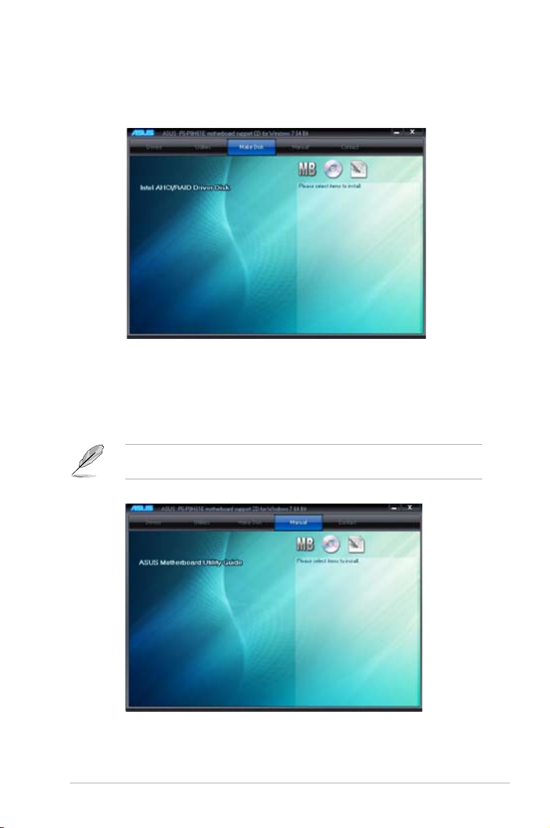
2.3.3 Make Disk menu
The Make disk menu allows you to make a AHCI driver disk.
2.3.4 Manual menu
The Manual menu contains the list of supplementary user manuals. Click an item to open the
folder of the user manual.
Most user manuals are in Portable Document Format (PDF). Install the Adobe® Reader
from the Utilities menu before opening a user manual.
2-6
Chapter 2: Starting up
2.3.6 Other information
The icons on the top right corner of the screen give additional information on the motherboard
and the contents of the support DVD. Click an icon to display the specied information.
Motherboard Info
Displays the general specications of the motherboard.
2.3.5 ASUS Contact information
Click the Contact tab to display the ASUS contact information. You can also nd this
information on the inside front cover of this user guide.
2-7
ASUS P6-P8H61E
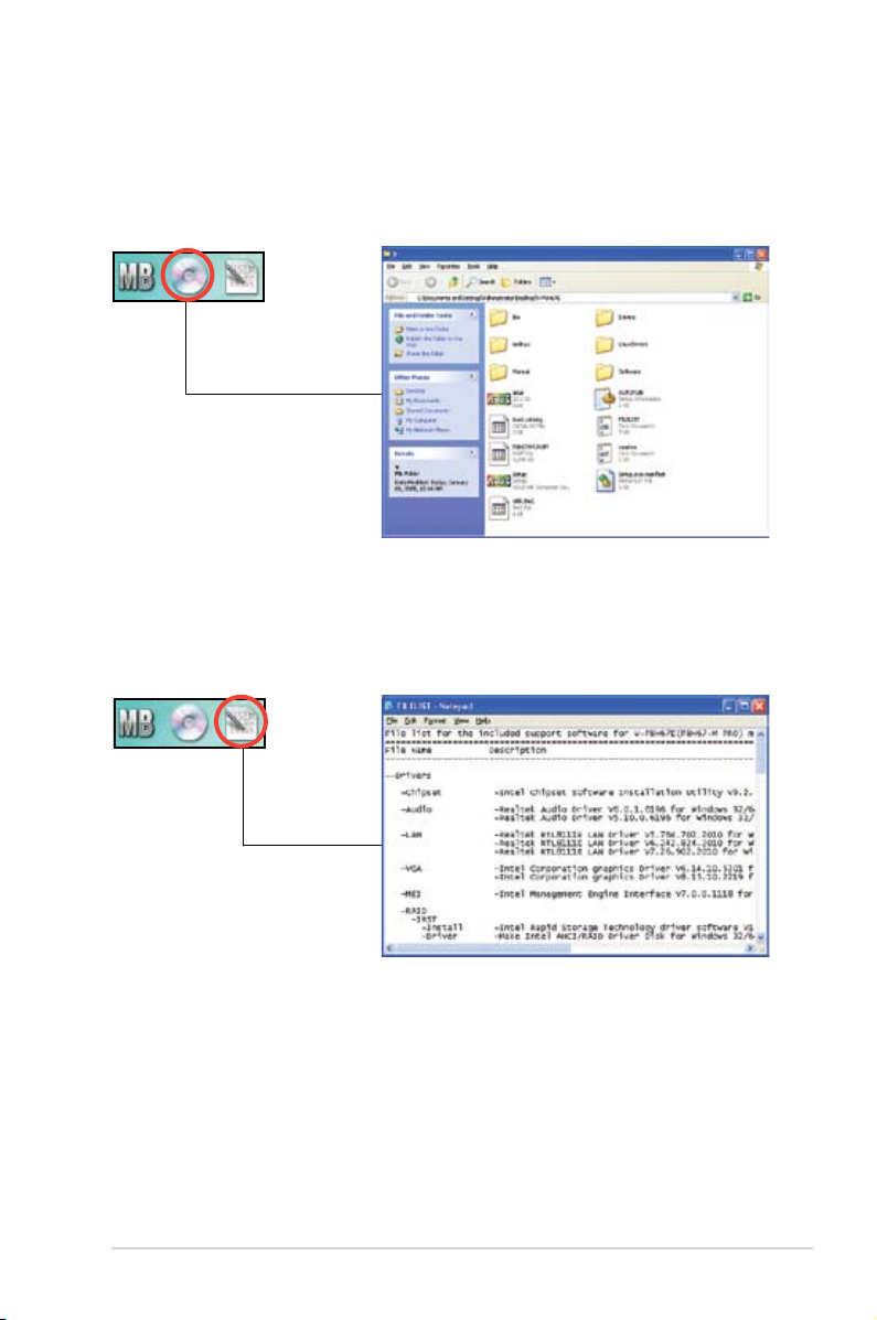
Browse this DVD
Displays the support DVD contents in graphical format.
Filelist
Displays the contents of the support DVD and a brief description of each in text format.
Loading...