


 Loading...
Service Source
MacBook Pro
(17-inch,17-inchCore2Duo and17-inch2.4GHz)
5 June 2007
© 2007 Apple Inc. All rights reserved.

MacBook Pro
(17-inch, 17-inch Core 2 Duoand 17-inch 2.4GHz)
Contents
Basics
General Information |
6 |
Product View 6 |
|
Overview 6 |
|
Serial Number and Ethernet ID 13 |
|
Tools 13 |
|
Electrostatic Discharge (ESD) 14 |
|
Service Manual Note |
14 |
Kapton® Tape Note |
14 |
Cable Routing Note |
14 |
Screw Measurement and Callout Note 14 |
|
Temperature Concerns 14 |
|
Adjustments
Latch Adjustment 16
Take Apart
Foot 20
Battery 23 |
|
|
Memory |
25 |
|
Replacement Procedure |
28 |
|
Top Case |
30 |
|
Replacement Procedure |
35 |
|
Keyboard |
40 |
|
Replacement Procedure |
55 |
|
AirPort Extreme Card |
64 |
|
Hard Drive 69 |
|
|
ii

Bluetooth Card and Antenna 73
Infrared Board 79
Replacement Procedure 81
Optical Drive 83
Handling Slot-Load Optical Drives 88
Replacement Procedure |
91 |
|
Removing a Stuck Disc from an Optical Drive 92 |
||
Backup Battery 94 |
|
|
Ambient Light Sensors |
99 |
|
Speakers and Microphone 101 |
||
Left I/O Board 107 |
|
|
ExpressCard Cage |
114 |
|
Fans 115 |
|
|
Logic Board 122 |
|
|
Replacement Procedure |
132 |
|
Battery Cable Assembly |
139 |
|
Thermal Sensors |
141 |
|
Heatsink 145 |
|
|
Bottom Case 147 |
|
|
Display Assembly |
149 |
|
Replacement Procedure |
152 |
|
Troubleshooting
General Information |
156 |
|
Wire and Flex Cables |
156 |
|
Microphone and Camera wires |
157 |
|
Hardware Diagnostics |
157 |
|
Troubleshooting Aids and Tips |
159 |
|
MacBook Pro Firmware Updates |
161 |
|
Mac OS X: Firmware Updates for Intel-based Macs 161 Software Troubleshooting Tips and Tools 162 Application compatibility 164
Universal binary 164 Rosetta 164
iii

Hardware Symptoms 165
How to Use the Symptom Charts 165
Startup 165
AirPort Extreme 170
Battery 171
Bluetooth 173
Display 174
ExpressCard/34 175
Hard Drive 176
Apple Remote 177
Infrared Board 177
Built-in iSight Camera 178
Keyboard 179
Microphone 180
Modem (External) 181
Ports 183
Sound 186
Trackpad 187
Misc. Symptoms 189
Views
MacBook Pro (17-inch) Exploded View 192
MacBook Pro (17-inch Core 2 Duo) Exploded View 193 MacBook Pro (17-inch 2.4GHz) Exploded View 194
Screw Chart 195
Architecture 196
iv

Service Source
Basics
MacBook Pro
(17-inch, 17-inch Core 2 Duo
and 17-inch 2.4GHz)
© 2007 Apple Inc. All rights reserved.
 General Information
Product View
Overview
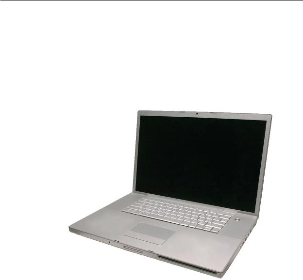
The MacBook Pro (17-inch), MacBook Pro (17-inch Core 2 Duo), and MacBook Pro (17-inch 2.4/2.2GHz) represent three generations of the MacBook Pro professional notebooks. The original MacBook Pro (17-inch) is based on the Intel Core Duo chip, while the latter two MacBook Pros (17inch Core 2 Duo and 17-inch 2.4/2.2GHz) are based upon two successive iterations of the more recent Intel Core 2 Duo chip, with the latest increasing processor speeds from 2.33GHz to 2.4GHz.
The newest MacBook Pro (2.4/2.2GHz) supercedes the previous MacBook Pro (17-inch) models in four ways: the bus speed has increased to 800MHz, the system now addresses up to 4 GBs of
RAM, it sports a new NVIDIA GeForce 8600M GT graphics chip, and can come configured-to-order with a higher resolution 1900 x 1200 (antiglare or glossy) display.
The only outwardly visible difference between the three machines is a small opening in the display bezel for the LED to the right of the iSight camera in the original MacBook Pro (17-inch).
MacBook Pro (17-inch, 17-inch Core 2 Duo & 17-inch 2.4GHz) Basics— General Information 6

Main service and feature differences from previous models:
|
MacBook Pro (17-inch |
MacBook Pro (17-inch |
MacBook Pro (17-inch) |
|
2.4GHz) |
Core 2 Duo) |
|
Microprocessor |
2.4GHz Core 2 Duo |
2.33GHz Core 2 Duo |
2.16GHz Core Duo |
Bus Speed |
800 MHz |
667 MHz |
667 MHz |
Max RAM |
4 GB |
3 GB |
2 GB |
Graphics Chip |
NVIDIA GeForce |
ATI x1600 |
ATI x1600 |
|
8600M GT |
|
|
Display |
CCFL Backlight |
CCFL Backlight |
CCFL Backlight |
Optical Drive |
8x DVD Dual Layer |
8x DVD Dual Layer |
8x DVD Dual Layer |
|
Superdrive |
Superdrive |
Superdrive |
New Parts and Procedures
Main Memory
The memory connector is a stacked memory design. The newest MacBook Pro (17-inch 2.4GHz) supports up to 4GB, the MacBook Pro (17-inch Core 2 Duo) supports up to 3GB, and the MacBook Pro (17-inch) supports up to 2GB of RAM. Note that in the MacBook Pro (17-inch Core 2 Duo) it will be a perfectly bootable system with two (2) 2GB RAM modules—and even About This Mac will report 4GB of installed memory—but the system will only address 3GB of the installed RAM.
Keyboard
The latest MacBook Pro (17-inch 2.4GHz) has a newer keyboard design with no side tabs. No more need to bend the corners of the keyboard to finesse it into the keyboard well.
Changes between the MacBook Pro (17-inch Core 2 Duo) and MacBook Pro (17-inch) keyboards were improved backlighting, and the re-programming of the caps lock key to fix a developer keyboard mapping issue. Thus, the keyboards among all 17-inch MacBook Pro models are not interchangeable.
17-inch MacBook Pro keyboards utilize flex cables that are incompatible with keyboards from the
15-inch models of the MacBook Pro as well as PowerBook G4s.
ExpressCard Cage
The ExpressCard cage enclosure for the MacBook Pro (17-inch 2.4GHz) is modified with more openings. In addition,“pocket screws” now secure the cage to the Left I/O board. These larger headed screws make contact with EMI gaskets on the bottom case for improved noise isolation.
ExpressCard replaced the PCMCIA card cage in the PowerBook G4. The ExpressCard standard supports two sizes cards, 34mm and 54mm width. MacBook Pro supports the 34mm standard.
MacBook Pro (17-inch, 17-inch Core 2 Duo & 17-inch 2.4GHz) Basics— General Information 7

Main Logic Board
The original MacBook Pro (17-inch) is based on the Intel Core Duo chip, while the latter two MacBook Pros (17-inch Core 2 Duo and 17-inch 2.4/2.2GHz) are based upon two successive iterations of the more recent Intel Core 2 Duo chip, with the latest increasing processor speeds from 2.33GHz to 2.4GHz.
All ports remain the same. The security lock slot is on the right side of the system. Composite and S-video connections are now only available using an optional Apple DVI to Video adapter.
The boot architecture of the MacBook Pro is based on Extensible Firmware Interface (EFI), replacing Open Firmware (OF) of PowerBook G4 days. Boot snag keys such as “C” for boot from the optical drive,“N” for network boot, and “T” for Target Disk Mode stay the same under EFI. To launch Apple Hardware Test (AHT) from the Mac OS X Install disc, you must hold down the “D” key during boot.
JST connectors
Unlike the MacBook Pro (17-inch), the MacBook Pro (17-inch Core 2 Duo and 2.4GHz) utilize JST wire bundle connectors that disengage by lifting up and pulling the connector out of its mating part on the logic board. To reconnect, just snap the connector back in, making sure it is seated securely. The fans, thermal sensors, and backup battery all use this connector.
Main Battery
All MacBook Pro 17-inch models use battery packs built with the same lithium polymer battery technology used in our iPod product line, though the basic chemistry is no different than previous lithium ion cells. An unchanged battery controller keeps the battery calibration procedure the same as it has been since the PowerBook G4 (Dual Layer SD).
Temperature Concerns
The customer may perceive each new system to run hotter than previous models. However, the normal operating temperature will be well within national and international safety standards. If a customer is concerned about the heat generated by their machine, to prevent an unnecessary repair compare a customer’s computer to a running model, if available, at your repair site.
For more information on temperature concerns and customer perception, refer to Knowledge Base article 30612: Apple Notebooks: Operating Temperature.
Backup Battery
The backup battery is not rechargeable. It only provides power to the real time clock and does not support system memory.
Without a power adapter connected, when you swap the finished goods battery in a running system, it must be done from sleep. The system will shutdown when you remove the battery. When you power back up, it will boot up from SafeSleep, a hibernation state.
MacBook Pro (17-inch, 17-inch Core 2 Duo & 17-inch 2.4GHz) Basics— General Information 8

AirPort Extreme
The MacBook Pro (17-inch Core 2 Duo and 2.4GHz) utilize an AirPort Extreme card with a threewire 802.11g antenna. The length of each wire and its color will help distinguish which wires go to which terminals on the card (black = longest/left, gray = medium/middle, blue = shortest/right).
The MacBook Pro (17-inch) uses the same AirPort Extreme card as the 15-inch MacBook Pro and does not support Bluetooth. It is the same form factor used in the iMac (Early 2006). However, there are two version of these cards, and they are not interchangeable.
The AirPort antenna for all 17-inch MacBook Pro models is located in the clutch barrel underneath the gray plastic window.
Bluetooth
Each 17-inch MacBook Pro model has a Bluetooth module with its own separate antenna, both located in a plastic bracket to the left side of the hard drive.
However, unlike the original MacBook Pro (17-inch), the Bluetooth bracket in both the MacBook Pro (17-inch Core 2 Duo) and MacBook Pro (17-inch 2.4GHz) comes wrapped in a foil EMI shield.
MacBook Pro (17-inch, 17-inch Core 2 Duo & 17-inch 2.4GHz) Basics— General Information 9

Mass Storage (hard drive and optical drive)
The hard drive interface for all MacBook Pros is Serial ATA (SATA); thus, previous PowerBook hard drives will not work in this system.
The optical drive in all 17-inch MacBook Pro models is basically the same mechanism used in the PowerBook G4 (17-inch Double-Layer SD), but with updated firmware.You should not interchange the two parts.
Speakers
All 17-inch MacBook Pro models sport four speakers with two separate speaker modules (left and right), each with two speakers each. Since the system can output a lot of sound, it is very
important to make sure screws are properly tightened down. As a mobile product, a loose screw can eventually work itself free, and using the speakers at elevated volumes can also work toward loosening a screw that is not properly installed.
In addition, each speaker is driven by its own amplifier, as is the headphone port. As such, troubleshooting between speaker and left I/O board failures will require some part swapping to pinpoint the problem module (see the Sound heading in Troubleshooting section).
Infrared Board and the Apple Remote
The infrared port is placed on the front of the unit just to the left of the display latch button. This port is used in conjunction with the Apple Remote provided with each unit. It can be used to control Front Row software that manages your music, photos and videos. The remote can also be used to control other applications as well.
Top Case
For all MacBook Pro 17-inch models, the sleep magnet is located on the side of the display bezel, and the sleep sensor is located to the right side of the top case just around the bottom of the perforated speaker openings.
Power Adapter
All MacBook Pro models use an Apple 85-Watt Portable Power Adapter with the revolutionary MagSafe power connector. It is not compatible with any previous notebook computer.
iSight Camera
An iSight Camera is built-in into the display bezel of all 17-inch MacBook Pro models, allowing a user to capture video and take still photos. A green LED to the right of the camera glows when the camera is on.
MacBook Pro (17-inch, 17-inch Core 2 Duo & 17-inch 2.4GHz) Basics— General Information 10
Unlike the standalone iSight camera, the microphone is not integrated with the camera. It is located by the left speaker.
iSight Camera Status LED
The opening for the green status LED to the right of the camera on the MacBook Pro (17-inch) no does not appear in the display bezel of the MacBook Pro (17-inch Core 2 Duo and 2.4 GHz). When the LED lights up, it appears through a clever pattern of micro perforations.
Display Takeapart
With all MacBook Pro 17-inch models, we still utilize the whole display clamshell as a service part. All parts including the LVDS cable are serviced with the whole clamshell module.
MacBook Pro (17-inch, 17-inch Core 2 Duo & 17-inch 2.4GHz) Basics— General Information 11

Identifying the MacBook Pro (17-inch, Core 2 Duo, and 2.4GHz)
Below are views of the MacBook Pro (17-inch, 17-inch Core 2 Duo and 17-inch 2.4GHz), with identifying features.The different iSight LEDs among models is covered in the previous section.
Left side: MagSafe™ magnetic power connector with two USB ports and ExpressCard.
Right side: Security lock slot; USB, FireWire 400, FireWire 800, Ethernet and DVI video ports
Front: Infrared sensor window.
Display bezel: MacBook Pro.
MacBook Pro (17-inch, Core 2 Duo & 2.4GHz) Rear: Grey antenna window in the clutch cover.
MacBook Pro (17-inch Core 2 Duo & 2.4GHz) Rear: Wider venting than previous MacBook Pro.
MacBook Pro (17-inch, 17-inch Core 2 Duo & 17-inch 2.4GHz) Basics— General Information 12
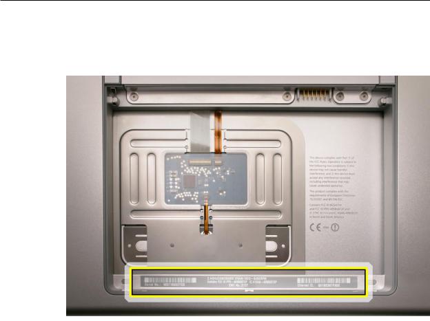
Serial Number and Ethernet ID
The Serial Number and Ethernet ID are located in the battery bay.
Tools
This procedure requires the following tools:
•Clean non-marring work surface
•ESD wrist strap and mat
•Multi-compartment screw tray (such as a plastic ice cube tray)
•#0 Phillips screwdriver (magnetized)
•Torx T6 screwdriver (magnetized)
•Black stick (nylon probe 922-5065) (or other non-conductive nylon or plastic flat-blade tool
•Razor knife
•Needle-point metal probe
•Needlenose pliers
•Kapton tape (922-1731 (0.5-inch x 12-yard roll))
•Thermal grease (922-7144, Pkg. of 3 syringes)
•Gasket kit (076-1268)
•Isopropyl alcohol cleaning wipes
•Fine-point felt-tip permanent marker
•Apple Pro keyboard and mouse (for troubleshooting)
MacBook Pro (17-inch, 17-inch Core 2 Duo & 17-inch 2.4GHz) Basics— General Information 13

Electrostatic Discharge (ESD)
Use a properly grounded ESD wrist strap and mat when working on the inside of the computer.
Service Manual Note
In this manual, graphics or photos are intended to help illustrate procedures or information only, and may show different levels of disassembly, board colors, configurations, or computer models, than your computer.
Kapton® Tape Note
Kapton tape is used to secure cables and connectors where necessary.
During disassembly, note any Kapton tape use and locations—reapply in the same manner. Do not over apply or build up tape on top of old tape; space tolerances are tight and build up or extraneous use of tape may cause pressure on other components.
Cable Routing Note
The MacBook Pro matches the same one-inch enclosure height established with the PowerBook G4 17-inch series of systems. The placement of parts and wiring is critical.
During disassembly, note cable routing. Reassemble in the same manner. Verify that cables do not route over components when they should route into lower positions or channels. Verify that the cables are not strained or applying pressure onto other components.
Screw Measurement and Callout Note
All screw measurements given are the specified full length. Actual measured lengths may vary.
Screw part numbers were assigned using a pre-production unit and are subject to change.
Temperature Concerns
The customer may perceive each new system to run hotter than previous models. However, the normal operating temperature will be well within national and international safety standards. If a customer is concerned about the heat generated by their machine, to prevent an unnecessary repair compare a customer’s computer to a running model, if available, at your repair site.
For more information on temperature concerns and customer perception, refer to Knowledge Base article 30612: Apple Notebooks: Operating Temperature.
MacBook Pro (17-inch, 17-inch Core 2 Duo & 17-inch 2.4GHz) Basics— General Information 14
Service Source
Adjustments
MacBook Pro
(17-inch, 17-inch Core 2 Duo
and 17-inch 2.4GHz)
© 2007 Apple Inc. All rights reserved.

 Latch Adjustment
Overview
If the display latches do not secure the display to the top case, or release before the latch release button is pushed, an adjustment to the latch hooks can be made to correct this. Alternately, the computer can be sent to the Apple Repair Center for service.
The display latches consists of a latch mechanism under the top case (it’s actually attached to the bottom case frame) and two pivoting latch hooks within the display assembly. The hooks are pulled down into the latch mechanism by a magnet as they approach the top case, and they are secured under an overhang on the latch mechanism.
Tools
This procedure requires the following tools:
•Black stick (or other non-marring nylon or plastic pointed tool)
•Magnet
Preliminary Steps
Warning: While performing the following procedures, notice the hooks as they are drawn out of the display housing and into the slots in the top case. If adjustments to either latch hook are performed later, they must be adjusted only very slightly, to stay within the slot on the top case.
Before performing the latch adjustment, test the current operation of the latches:
1.Push the display down to about two inches from the top case. Then push the display very slowly until it just touches the top case, and immediately release.
If working properly, the latches should secure the display to the top case throughout the following tests:
•Pounding firmly on the table top, to the left and right of the computer.
•Pulling up on the sides of the display.
Repeat the above procedures multiple times to verify proper operation of the latches.
2.Whether or not the latches functioned properly, use the following procedures to achieve or to verify proper latching function.
MacBook Pro (17-inch, 17-inch Core 2 Duo & 17-inch 2.4GHz) Adjustments — Display Latch 16

Procedure
Note: The latch mechanism under the top case of the computer has a small amount of right and left play (less than 1 mm), and can shift during normal operation.
The following procedures will test the latching function with the latch mechanism at its maximum right and left positions, and the latch hooks will be very slightly adjusted, as necessary.
Important: The latch hook metal can become brittle and break if it is bent too much, especially if it is over-bent and bent back. Work carefully and with due restraint to avoid over-bending the latch hook. If the latch hook breaks, new latch hooks will need to be ordered and replaced.
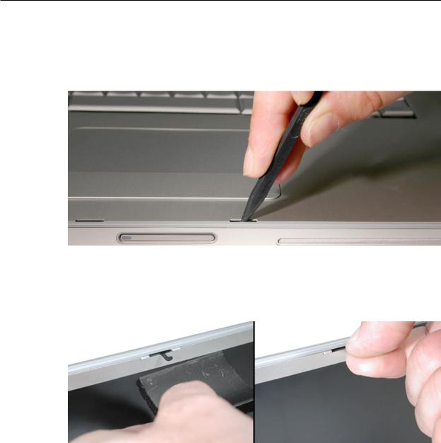
1.Open the display and note the edges of the latch mechanism underneath the top case, shown below, just to the right and left of the latch release button. This mechanism catches both left and right latch hooks on the display assembly.
2.Use a black stick to push the latch mechanism, at the location shown below, to move it to the left as needed (less than 1 mm) or its corresponding location on the left side of the latch release button to move it right (less than 1 mm).
MacBook Pro (17-inch, 17-inch Core 2 Duo & 17-inch 2.4GHz) Adjustments — Display Latch 17
3.Perform the testing procedures in step 1 of the Preliminary Steps, above.
4.If the latch functions properly, skip to step 8; otherwise, if the latch hook requires an adjustment refer to the following steps below.
5.If the latch does not function properly, adjust the latch hook as follows:
Open the display to a 90-degree angle and use a magnet to draw the latch hook out. Tightly grasp it between your thumb and forefinger as close to the display as possible, as shown.
6.Carefully exert a very slight controlled downward pressure on the latch hook.
Important: Do not push only with your thumb. Hold the latch hook tightly between your thumb and forefinger to support the latch hook and prevent too much bending force.
7.Release the latch hook and perform the latch tests as before. Continue the above procedure until the latch functions properly.
8.Again, if needed, use a black stick to push on the latch mechanism, as shown above, to move it to the left or right (about 1 mm) to re-center the mechanism over the latch release button.
9.Repeat the previous latch closing tests, and latch hook adjustment if needed, until the latch works properly in this position.
MacBook Pro (17-inch, 17-inch Core 2 Duo & 17-inch 2.4GHz) Adjustments — Display Latch 18
Service Source
Take Apart
MacBook Pro
(17-inch, 17-inch Core 2 Duo
and 17-inch 2.4GHz)
© 2007 Apple Inc. All rights reserved.
 Foot
Foot
Tools
This procedure requires the following tools:
•Foot kit
•Tweezers or needlenose pliers
•Soft cloth
Preliminary Step
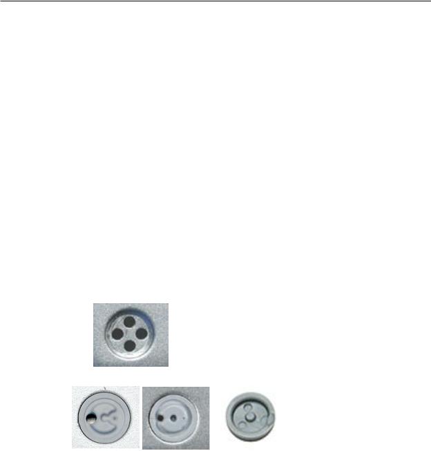
Before you begin, check the foot location that needs replacement and verify that the case plug is attached. Also verify that the case plug, and the case foot in the kit, match the pictures below.
Plug Area on Bottom Case |
Matching Foot |
Action |
Missing case plug |
Not available for |
Replace the bottom case, or |
|
replacement |
send to Apple Repair Center. |
|
|
|
Case plug (either one) |
Case foot |
Continue with the procedure, |
|
|
matching the foot to either |
|
|
plug on the bottom case. |
|
|
|
MacBook Pro (17-inch, 17-inch Core 2 Duo & 17-inch 2.4GHz) Take Apart — Foot 20
Procedure
Warning: The glue used in this procedure can bond instantly to skin. Do not touch the glue. In the event of contact, review the safety instructions at the end of this document. For additional information, refer to the glue manufacturer:
Elmer’s Products, Inc. Columbus, OH. 43215-3799 www.krazyglue.com
1.Place the computer upside down on a clean, lint-free cloth or other nonabrasive surface.
2.Select a foot from the kit. Verify that the case plug and case foot match (refer to the images shown in the table). Do not use a foot that does not match.
3.Make sure the plug area on the bottom case is clean. If any portion of the soft rubber foot remains, remove it so that only the hard plastic plug is visible.
Important: When positioning the foot, make sure the indents and bumps of the rubber foot match up and fit into the corresponding indents and bumps in the plug.This ensures a balanced and level fitting.
MacBook Pro (17-inch, 17-inch Core 2 Duo & 17-inch 2.4GHz) Take Apart — Foot 21

4.Warning: GLUE IS AN EYE AND SKIN IRRITANT. BONDS SKIN INSTANTLY. Do not touch the glue at any time. Before opening the glue, review the safety instructions below.
Important: The glue tube included in the kit is sealed until first use. Do not break the seal until you are ready to use the glue. To break the seal, hold the tube upright and away from you. Place the hollow nozzle cap on the tube and tighten it all the way down. The tube is then ready to dispense the glue through the nozzle cap.
5.Apply one drop of glue to the plug on the bottom case. Do not spread the glue.
6.Using tweezers or needlenose pliers, carefully position the new foot so its textured surface fits into the inner ring of the plug.
7.Using the end of the tweezers or pliers—not your finger—lightly press and hold the foot in place for 30 seconds.
8.Before turning over the computer, allow the glue to set for at least 15 minutes.
9.Discard the tube of glue.
SAFETY INSTRUCTIONS:GLUE IS AN EYE AND SKIN IRRITANT. BONDS SKIN INSTANTLY.
Contains ethyl cyanoacrylate. Avoid contact with skin and eyes. If eye or mouth contact occurs, hold eyelid or mouth open and rinse thoroughly but gently with water only for 15 minutes and
GET MEDICAL ATTENTION. Liquid glue will sting eye temporarily. Solidified glue may irritate eye like a grain of sand and should be treated by an eye doctor.
If skin bonding occurs, soak in acetone-based nail polish remover or warm soapy water and carefully peel or roll skin apart (do not pull). Contact through clothing may cause skin burn.
If spilled on clothing, flush with cold water. Avoid prolonged breathing of vapors. Use with adequate ventilation. KEEP OUT OF REACH OF CHILDREN.
MacBook Pro (17-inch, 17-inch Core 2 Duo & 17-inch 2.4GHz) Take Apart — Foot 22

 Battery
Tools
This procedure requires the following tools:
•Clean non-marring work surface
Preliminary Steps
Warning: Always shut down the computer before opening it to avoid damaging its internal components or causing injury. After you shut down the computer, the internal components can be very hot. Let the computer cool down before continuing.
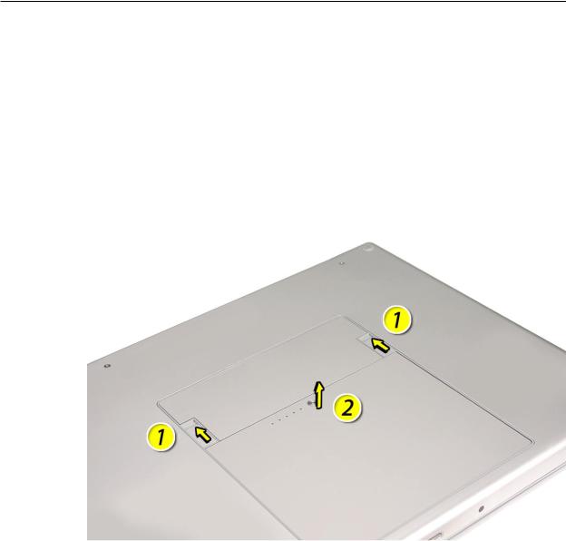
Part Location
MacBook Pro (17-inch, 17-inch Core 2 Duo & 17-inch 2.4GHz) Take Apart — Battery 23
Procedure
Warning: If the computer has been recently operating, allow it to cool down before performing this procedure.
1.Shut down the computer.
2.Disconnect the power cord and any other cables connected to the computer.
3.Place the computer upside down.
4.Slide both battery latches away from the battery and lift the battery out of the battery bay.
MacBook Pro (17-inch, 17-inch Core 2 Duo & 17-inch 2.4GHz) Take Apart — Battery 24
 Memory
Tools
This procedure requires the following tools:
•#0 Phillips screwdriver (magnetized)
•Clean non-marring work surface
•ESD wrist strap and mat
Preliminary Steps
Before you begin, remove the following:
•Battery
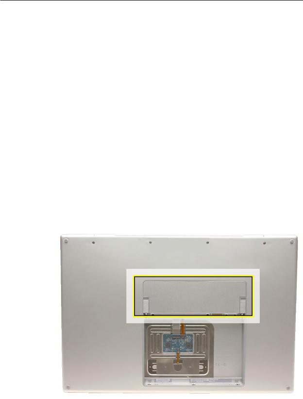
Part Location
MacBook Pro (17-inch, 17-inch Core 2 Duo & 17-inch 2.4GHz) Take Apart — Memory 25

Procedure
Warning: If the computer has been recently operating, allow it to cool down before performing this procedure.
1.Place the computer upside down.
2.Remove four screws from the memory door.
3.Remove the door, as shown.
Notes:
•If only one memory card is installed, the factory installs it in the bottom memory slot.
•Memory must be removed from the top slot before removing from the bottom slot.
MacBook Pro (17-inch, 17-inch Core 2 Duo & 17-inch 2.4GHz) Take Apart — Memory 26
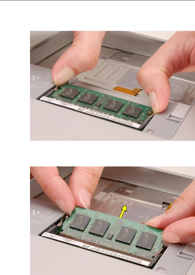
4.To remove memory cards, carefully spread the two locking tabs for the slot (top or bottom) away from the card on both sides and allow the card to pop up slightly.
5.Pull the card straight back and out of the memory slot. Handle the memory card by the edges only, taking care not to touch the gold contacts.
MacBook Pro (17-inch, 17-inch Core 2 Duo & 17-inch 2.4GHz) Take Apart — Memory 27

Replacement Procedure
Notes:
•DDR memory cards do not fit in this slot, only DDR2 (different notch location).
•If installing two cards, install into the bottom slot first.
•Align the notch in the memory card with the tooth in the slot before inserting.
1.To install memory cards, insert them at a 30-degree angle. Note: Insert the bottom card behind the locking tabs of the top slot.
2.Firmly push the card straight into the slot until it is fully and securely seated along its length. Note: If the back of the card drops down before it is fully seated, raise it up enough to push it fully into the slot.
3.When the card is fully seated, push the card straight down until the tabs click onto both sides of the card, locking it into place.
MacBook Pro (17-inch, 17-inch Core 2 Duo & 17-inch 2.4GHz) Take Apart — Memory 28

4.Verify that the card is fully seated by pushing firmly with your thumbs.
5.Check that the cards are secured by the brackets on both sides.
6.Install the memory door.
7.Replace the battery.
8.Use Apple System Profiler to verify that the memory is recognized. (Choose the menu bar Apple logo ( ) > AboutThis Mac, click More Info..., select the System Profile tab, open the Memory Overview.)
NOTE: The maximum supported amount of memory in the MacBook Pro (17-inch) is 2GB, in the MacBook Pro (17-inch Core 2 Duo) is 3GB, and in the MacBook Pro (17-inch 2.4GHz) is 4GB.
Important: While the MacBook Pro (17-inch Core 2 Duo) will have a perfectly bootable system with two (2) 2GB RAM modules installed—and even About This Mac will report 4GB of installed memory—the system will only be able to address 3GB of that installed RAM.
See MacBook Pro (Core 2 Duo):Memory Specifications for more information.
MacBook Pro (17-inch, 17-inch Core 2 Duo & 17-inch 2.4GHz) Take Apart — Memory 29

 Top Case
Tools
This procedure requires the following tools:
•#0 Phillips screwdriver (magnetized)
•Torx T6 screwdriver (magnetized)
•Black stick (nylon probe 922-5065) or other non-conductive nylon or plastic flat-blade tool
•Multi-compartment screw tray (such as a plastic ice cube tray)
Preliminary Steps
Before you begin, remove the following:
•Battery
•Memory
Part Location
MacBook Pro (17-inch, 17-inch Core 2 Duo & 17-inch 2.4GHz) Take Apart — Top Case 30
Loading...