


 Loading...
Service Source
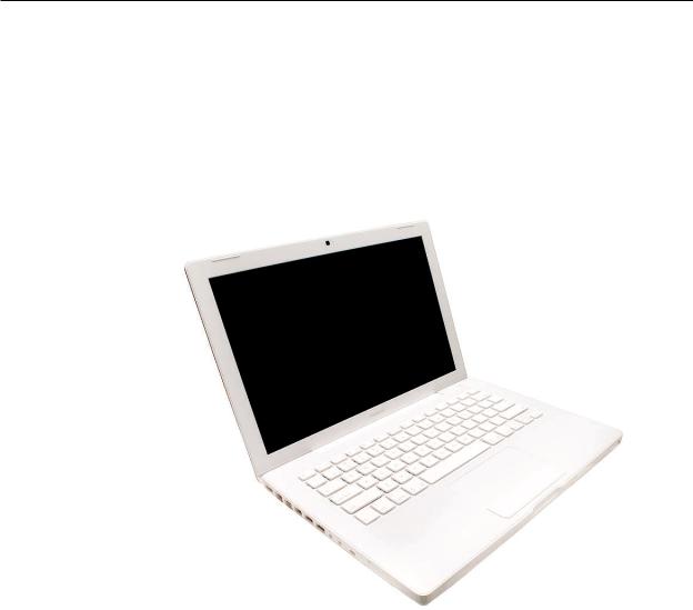
MacBook (13-inch)
MacBook (13-inch)
MacBook (13-inch Late 2006)
MacBook (13-inch Mid 2007)
Updated 27 July 2007
© 2006, 2007 Apple Inc. All rights reserved.

MacBook (13-inch)
Contents
Take Apart
General Information |
7 |
|
|
|
|
What’s New 7 |
|
|
|
|
|
Product Configurations |
8 |
|
|
||
Vertical-Insert Connectors |
10 |
|
|||
Tools 10 |
|
|
|
|
|
Power Adapter 11 |
|
|
|
|
|
Temperature Concerns |
11 |
|
|
||
Note About Images in This Manual |
11 |
||||
Logic Board Springs |
12 |
|
|
|
|
Simplified Flowchart for Take Apart |
13 |
||||
Battery 14 |
|
|
|
|
|
RAM Door (L-Bracket) |
17 |
|
|||
Memory (DIMMs) |
21 |
|
|
|
|
Removal Procedure |
22 |
|
|
|
|
Replacement Procedure |
23 |
|
|||
Removing a Stuck Memory Card 25 |
|||||
Hard Drive |
26 |
|
|
|
|
Top Case (with Keyboard) |
29 |
|
|||
Trackpad Cable (Late 2006 Model Only) 41 |
|||||
Procedure |
42 |
|
|
|
|
AirPort Extreme Card |
46 |
|
|
||
MagSafe DC-In Board |
51 |
|
|||
Left Speaker |
55 |
|
|
|
|
Battery Connector with Sleep Switch 59 |
|||||
Hard Drive Connector |
66 |
|
|||
Fan 72 |
|
|
|
|
|
ii

Heatsink |
75 |
|
|
|
Checking the Thermal Grease 79 |
|
|
||
Comparing Heatsinks 85 |
|
|
||
Bluetooth Holder |
86 |
|
|
|
Optical Drive 90 |
|
|
||
Handling Slot-Load Optical Drives |
100 |
|
||
Removing a Stuck Disc from an Optical Drive 104 |
||||
Optical Drive Cable 106 |
|
|
||
I/O Frame (with upper EMI shield) 110 |
||||
Logic Board 114 |
|
|
||
DIMM Lever Kit |
125 |
|
|
|
Backup Battery |
129 |
|
|
|
Bluetooth Antenna Board and Cable |
132 |
|||
Bluetooth Board |
136 |
|
|
|
Bluetooth-to-Logic Board Cable |
140 |
|
||
Subwoofer with Right Speaker Cable |
145 |
|||
Midframe |
151 |
|
|
|
Display Bezel 156 |
|
|
||
Removal Procedure 157 |
|
|
||
Replacement Procedure 160 |
|
|
||
Bezel Mounting Clips 163
Removal Procedure 164
Replacement Procedure 165
Spacers at Bezel Scoops 167
C-Channel 169
Clutch Block, Left 173
Clutch Block, Right 180
Clutch Caps 184
(Refer to“Clutch Block, Left”and“Clutch Block, Right”) 184
Display Module 185
Bottom Case 192
iii

Clutch Cover 196
Bezel Scoops, Left and Right 202 LCD Panel 206
Antenna Receptors and Cables, Top and Left 212
Antenna Receptor and Cable, Right (Late 2006 Model Only) 217
LCD Panel Assembly |
225 |
|
||
Removal Procedure 227 |
|
|||
Reinstallation Procedure 232 |
|
|||
Foil at Camera Bracket (Original MacBook Model) 240 |
||||
Spacers at Camera Bracket |
243 |
|||
Camera Assembly |
245 |
|
||
LVDS Cable with USB Line |
251 |
|||
Microphone Cable |
258 |
|
||
Inverter Board |
265 |
|
|
|
Inverter Cable |
268 |
|
|
|
Display Hinges, Left and Right 271 |
||||
Bezel Brace, Left |
274 |
|
|
|
Bezel Brace, Right |
276 |
|
||
Sleep Magnet |
280 |
|
|
|
Display Magnet Pairs |
283 |
|
||
Display Rear Housing |
287 |
|
||
Additional Procedures
General Information 291
Replacing Darfon Keycaps 292
Preliminary Steps 292
Part Location 292
Procedure 292
Replacing Mitsumi Keycaps 307
Preliminary Steps 307
iv

Part Location 307
Procedure 308
Troubleshooting
General Information 323
Troubleshooting Steps 324
Symptom Charts 327
Block Diagram 337
Views
External and Internal Views |
340 |
|
Front: Keyboard and IR Window 340 |
||
Back: Air Vents and Display Clutch |
341 |
|
Left Side:Ports 341 |
|
|
Right Side: Slot Drive 341 |
|
|
Battery Bay: Memory Card Levers and Hard Drive Pull Tab 342 |
||
Top Case Removed: Main Modules and Cable Routing 342 |
||
Screw Charts 348 |
|
|
Top Case Screw Locations 348 |
|
|
Display Module Screw Locations |
349 |
|
Logic Board Screw Locations |
350 |
|
LCD Panel Screw Locations 351 |
|
|
Screw Reference Chart, Part 1 of 3 |
352 |
|
Screw Reference Chart, Part 2 of 3 |
353 |
|
Screw Reference Chart, Part 3 of 3 |
354 |
|
Exploded Views 355
MacBook (13-inch)—Display Exploded View 355 |
|
|
MacBook (13-inch)—Main Exploded View 356 |
|
|
MacBook (13-inch Late 2006)—Display Exploded View |
357 |
|
MacBook (13-inch Late 2006)—Main Exploded View |
358 |
|
MacBook (13-inch Mid 2007)—Display Exploded View |
359 |
|
MacBook (13-inch Mid 2007)—Main Exploded View |
360 |
|
v
Service Source
Take Apart
MacBook (13-inch)
© 2006, 2007 Apple Inc. All rights reserved.
 General Information
What’s New
The MacBook (13-inch) portable computer is the first computer of its size featuring the Intel Core Duo processor and built-in iSight video camera.The main features and service differences (from similar-sized Apple portable computers) include:
•Higher resolution 13.3-inch LCD panel
•iSight camera built-in
•Infrared sensor on front right corner
•Hard drive is offered as a customer-replaceable module
•Digital audio-in
•MagSafe magnetic power connector
•Supports extended desktop
•Vertical-insert connectors—most of the cable connectors on the logic board use a new design that requires special insertion and extraction (refer to the section“Vertical-Insert Connectors”in this chapter)
•Feet on the bottom case are heat-staked, so they are not removable
MacBook (13-inch) Take Apart — General Information 7

•Built-in keyboard as part of top case
•Operating temperature is hotter than previous models (refer to“Temperature Concerns”in this chapter)
Product Configurations
The following table shows the MacBook (13-inch) model configurations at introduction:
Feature |
Good |
Better |
Best |
Intel Core Duo processor |
1.83 GHz |
2.0 GHz |
2.0 GHz |
Memory |
512 MB (x2) |
512 MB (x2) |
512 MB (x2) |
Hard Drive |
60 GB |
60 GB |
80 GB (120 GB) |
Optical Drive |
Combo, 9.5 mm |
Super, 9.5 mm |
Super, 9.5 mm |
Housing |
White |
White |
Black |
Display |
13.3-inch, 1280x800, 114 dpi, Low Reflection Glossy Polarizer (LRGP) |
||
Battery |
55-Whr Lithium Polymer |
|
|
Power Adapter |
60 W, A70, MagSafe MPM |
|
|
The following table shows the MacBook (13-inch Late 2006) model configurations at introduction:
Feature |
Good |
Better |
Best |
Intel Core 2 Duo processor |
1.83 GHz |
2.0 GHz |
2.0 GHz |
Memory |
512 MB (x2) |
1 GB (x2) |
1 GB (x2) |
Hard Drive |
60 GB |
80 GB |
120 GB, (160 GB, 200 |
|
|
|
GB) |
Optical Drive |
Combo, 9.5 mm |
Super, 9.5 mm |
Super, 9.5 mm |
Housing |
White |
White |
Black |
Display |
13.3-inch, 1280x800, 114 dpi, Low Reflection Glossy Polarizer (LRGP) |
||
Battery |
55-Whr Lithium Polymer |
|
|
Power Adapter |
60 W, A77, MagSafe MPM |
|
|
The following table shows the MacBook (13-inch Mid 2007) model configurations at introduction:
Feature |
Good |
Better |
Best |
Ultimate |
Intel Core 2 Duo processor |
2.0 GHz |
2.16 GHz |
2.16 GHz |
2.16 GHz |
Memory |
512 MB (x2) |
512 MB (x2) |
512 MB (x2) |
1 GB (x2) |
Hard Drive |
80 GB |
120 GB |
160 GB |
120 GB (Better) or |
|
|
|
|
160 GB, 200 GB (Best) |
Optical Drive |
Combo, 9.5 mm |
Super, 9.5 mm |
Super, 9.5 mm |
Super, 9.5 mm |
Housing |
White |
White |
Black |
White (Better) or |
|
|
|
|
Black (Best) |
Display |
13.3-inch, 1280x800, 114 dpi, Low Reflection Glossy Polarizer (LRGP) |
|||
Battery |
55-Whr Lithium Polymer |
|
|
|
Power Adapter |
60 W, A77, MagSafe MPM |
|
|
|
MacBook (13-inch) Take Apart — General Information 8
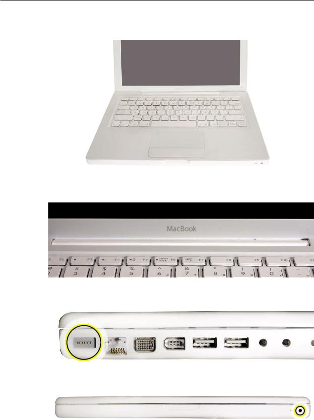
Keyboard integral to top case:
Product name on display bezel:
MagSafe power connector port:
Infrared window on front of computer:
For additional views of the computer, refer to the“Views”chapter at the end of this manual.
MacBook (13-inch) Take Apart — General Information 9
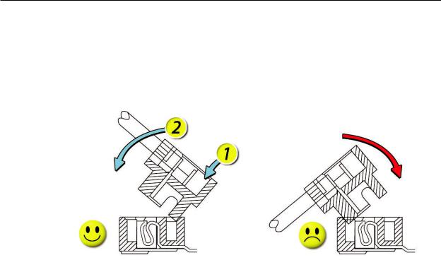
Vertical-Insert Connectors
Most of the cable connectors on the logic board use a new design that requires special insertion and extraction. Caution:To prevent damage to the connectors, install them from the front (away from the cable) when reconnecting vertical-insert cables to the logic board.
Tools
Caution: To prevent scratches or other cosmetic damage to the computer housing, use a soft cloth as a protective layer when removing and installing the external screws.
The tools required to service this computer include:
•Clean, soft, lint-free cloth
•Coin
•ESD wrist strap and mat
•Magnetic Phillips #0 screwdriver
•Magnetic Phillips #00 screwdriver (preferably with a long handle)
•Black stick (Apple probe tool, part number 922-5065) or other nonconductive nylon or plastic flatblade tool
•Access card (Apple part number 922-7172) to open the top case
•Jeweler’s flatblade screwdriver
•Needlenose pliers
•Stack of books, weighted boxes, or other means of support for display while removing screws from hinge
•Thermal grease (Apple thermal compound syringe, part number 922-7144)
•Alcohol wipes
•Permanent marking, felt-tip pen
•Standard size CD or DVD disc
•Flashlight or bright lamp
MacBook (13-inch) Take Apart — General Information 10
Power Adapter
Warning: The power adapter for this computer is unique to this model. It uses an MPM 4-pin adapter plug. Do not use this power adapter with any other portable computer. Power adapters from earlier iBook or PowerBook computers are not compatible and will not fit the MPM plug.
Temperature Concerns
This computer runs hotter than previous models. However, the normal operating temperature is well within national and international safety standards. Nevertheless, customers may be concerned about the generated heat. To prevent an unneeded repair, you can compare a customer’s computer to a running model, if available, at your repair site. For more information
on temperature concerns and customer perception, refer to Knowledge Base article 30612“Apple Notebooks:Operating Temperature.”
http://docs.info.apple.com/article.html?artnum=30612
Note About Images in This Manual
Because a pre-production model was used for most of the images shown in this manual, you may notice small differences in appearance between the image pictured and the computer you are servicing. However, although the appearance differs, the steps and sequence are the same unless noted.
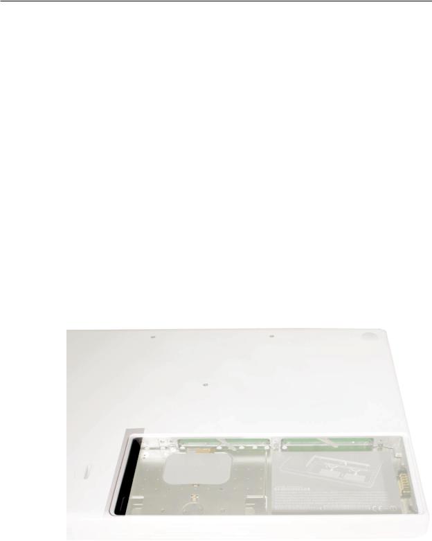
Memory Card Levers
Important: The following image shows the memory cards and hard drive installed in the battery bay. Note the correct position of the memory card levers. Some images pictured in this manual used a pre-production model, so the direction and appearance of the levers differ from the accurate depiction below. Refer to the Views chapter for other useful reference images.
MacBook (13-inch) Take Apart — General Information 11
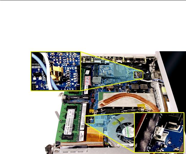
Logic Board Springs
Caution: When servicing the computer, be especially careful when working near the two springs on the logic board. Although the springs are flexible, they can be inadvertently torn, bent, or broken if a cable gets caught on them. A logic board might be considered unusable with one or more damaged springs. Check the structural integrity of the springs before completing a repair.
MacBook (13-inch) Take Apart — General Information 12
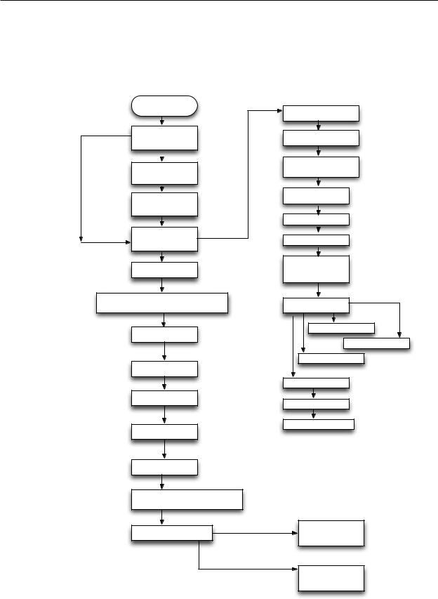
Simplified Flowchart for Take Apart
Although this flowchart does not include every serviceable part, you can use it as a reference after becoming familiar with the detailed removal procedures.
Remove
Battery
Remove RAM Door
(L-Bracket)
Remove Hard Drive
Remove RAM
(2 DIMMS)
Remove Top Case
with Keyboard
Remove ODD & C
Channel
Remove LCD Clutch Blocks: Left & Right
Remove Display
Module
Remove Display
Bezel
Remove Clutch Cvr
Remove Inverter
Remove L & R
Bezel Scoop
Disconnect LCD Panel Assembly
from Display Housing
Disconnect Bezel Braces
from LCD Panel
Remove MagSafe
DC-In Board
Remove Left Speaker
Remove AirPort
Extreme Card
Remove HDD Conn
Remove Fan
Remove Heatsink
Remove Batt Conn
(w/Sleep Switch)
Remove Optical
Drive & C-Channel
Remove Subwoofer
Remove Bluetooth
Remove R Speaker
Remove Midframe
Remove I/O frame
Remove Logic Board
Remove Antenna -
Inverter Cable
Assm.
Remove LVDS-
Cam-Mic Cable
Assm.
MacBook (13-inch) Take Apart — General Information 13
 Battery
Tools
•Clean, soft, lint-free cloth
•Coin
Part Location
Preliminary Steps
Warning: Always shut down the computer before opening it to avoid damaging the internal components or causing injury. After you shut down the computer, the internal components can be very hot. Let the computer cool down for 30 minutes before continuing
Procedure
1.Shut down the computer.
MacBook (13-inch) Take Apart — Battery 14
2.Wait 30 minutes to allow the computer’s internal components to cool.
3.Unplug all external cables from the computer except the power cord.
4.Unplug the power cord.
5.Put on an ESD wrist strap.
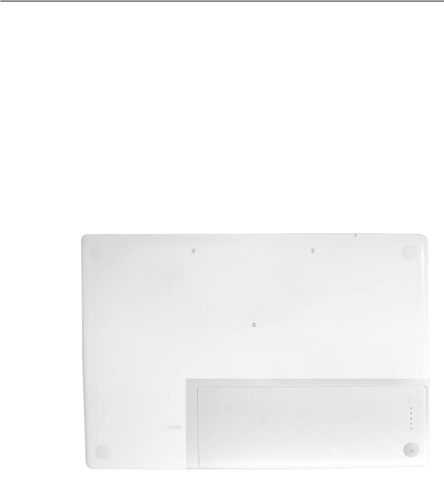
6.Turn over the computer and place it on a soft cloth.
7.Use a coin to release the battery latch. Turn the coin a quarter turn clockwise to unlock the battery.
Caution: To prevent scratches or other cosmetic damage to the bottom case, use only a coin to unlock and lock the battery.
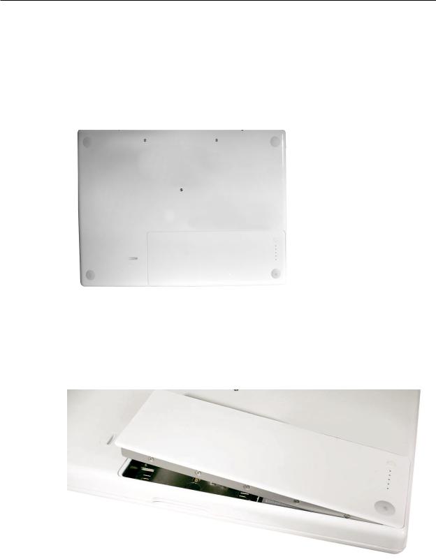
8.Lift out the battery from the battery bay.
9.To install the replacement battery, tilt the foot end of the battery into the battery bay first. Then press and hold down the other end of the battery as you turn the coin to lock it into place.
MacBook (13-inch) Take Apart — Battery 15
10. Reassemble and test the computer.
MacBook (13-inch) Take Apart — Battery 16
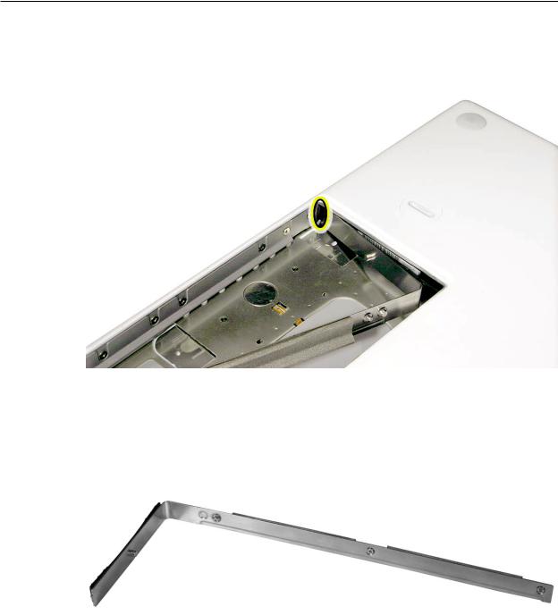
 RAM Door (L-Bracket)
Tools
•Soft cloth
•ESD wrist strap and mat
•Magnetic Phillips #0 screwdriver
•Black stick (Apple part number 922-5065) or other nonconductive nylon or plastic flatblade tool
Preliminary Steps
Before you begin, remove the battery.
Part Location
MacBook (13-inch) Take Apart — RAM Door 17
Procedure
1.With the computer closed and upside down on a soft cloth, touch a metal surface inside the battery bay to discharge any static electricity.
2.Loosen—but do not try to remove—the three captive screws along the RAM door.
MacBook (13-inch) Take Apart — RAM Door 18
3.Holding the long end of the L-shaped RAM door, pivot it out from the battery bay. (If necessary, use a black stick to tilt it up and out of the battery bay.) Be careful not to bend it.
Replacement Note: Before replacing the RAM door, make sure that
•Hard drive pull tab is not exposed
•Cards are fully inserted
•Memory card levers are fully down before replacing the RAM door
Replacement Note: Check that the replacement RAM door has a rubber cushion to protect the hard drive opening and two EMI gaskets to protect the memory card openings.
MacBook (13-inch) Take Apart — RAM Door 19
4.Replacement Note: Install the replacement RAM door by first aligning the short end at the notch near the hard drive opening.
Replacement Note: Use a black stick, if necessary, to tuck in the EMI gaskets so they do not protrude from the edge of the battery bay. Make sure the three screws align with the holes in the bottom case before tightening them.
5.Reassemble and test the computer.
MacBook (13-inch) Take Apart — RAM Door 20
 Memory (DIMMs)
This computer comes with a minimum of 512 MB of 667 GHz Double Data Rate 2 (DDR2)
Synchronous Dynamic Random-Access Memory (SDRAM) installed. It has two slots that can accept SDRAM Small Outline Dual Inline Memory Modules (SO-DIMMs). The slots are side-by-side on the logic board behind the RAM door. For best performance, memory should be installed
as pairs with an equal memory card in each slot.The maximum amount of memory for this computer is 2 GB, with 1GB DIMM installed in each slot.
Memory cards must meet these requirements:
•1.25 inch or smaller
•256 MB, 512 MB, or 1 GB
•200-pin
•PC-5300 DDR2 667 MHz Type RAM
Tools
•ESD wrist strap and mat
Preliminary Steps
Before you begin, remove
•Battery
•RAM door
Part Location
MacBook (13-inch) Take Apart — Memory 21
Removal Procedure
1.Touch a metal surface inside the battery bay to discharge any static electricity.
2.Put on an ESD wrist strap.
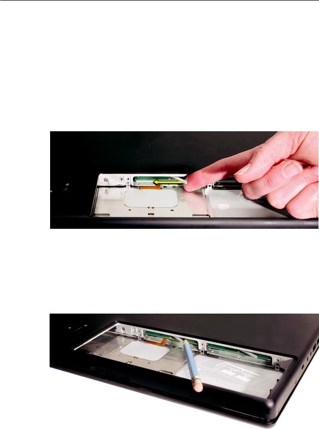
3.In one swift motion, use one finger to move the lever to the left and release it.This swift motion ejects the memory card.
Caution: The memory card eject levers are on a spring hinge that operates on a side-to-side horizontal plane.The mechanism can be damaged if the lever is forced outside of that horizontal movement.To prevent damage to a lever, move it swiftly—in one sideways direction only.
Note: Refer to the following if an issue occurs with a lever:
• |
If the lever wobbles, the lever may not be fully screwed in. Refer to“DIMM Lever Kit”in |
this chapter. |
|
• |
If the lever offers no resistance, the spring mechanism may be damaged. Refer to“DIMM |
Lever Kit”in this chapter. |
|
• |
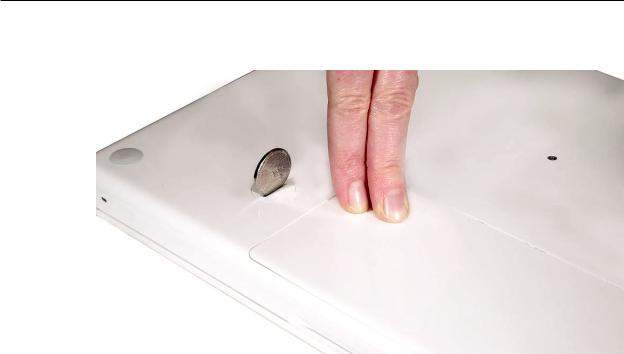
If the lever is stuck in a completely closed position (recessed underneath the bottom |
case), use a wooden pencil or black stick to gently pry it out, as shown below.
MacBook (13-inch) Take Apart — Memory 22
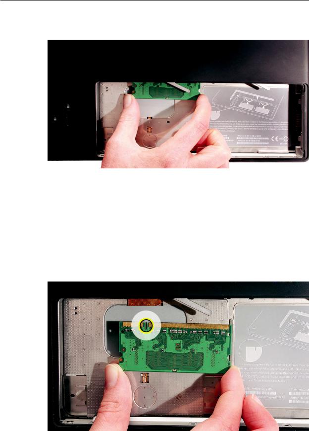
4.Holding the memory cards by the corners, slide them out from the battery bay.
Important: Do not touch the gold connectors. Handle the card only by its edges.
Note: A memory card might show a white residue when you remove it. This harmless substance acts as a lubricant when installing the memory card at the factory, but it is not required when reinstalling a memory card.
Replacement Procedure
1.Align the memory card so that the gold connectors face the slot and the notch is on the left. (The chip side of the board faces down.)
MacBook (13-inch) Take Apart — Memory 23
2.Use two fingers to push firmly on the edge of the memory cards. If there is a tight fit, installing the cards may take some force to ensure that they are fully inserted.
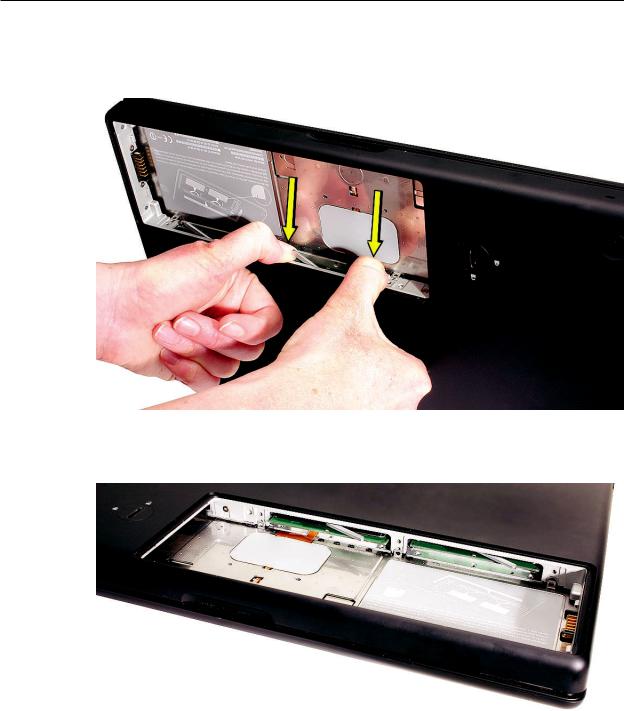
Important: When the cards are fully inserted, the edges of the cards are nearly hidden, as shown by the recessed card on the right in the image below.
3.If the levers do not return to the closed position, move them to close them.
4.Reassemble and test the computer.
5.Make sure the computer recognizes the new memory by opening System Profiler, clicking More Info, and clicking Memory.
MacBook (13-inch) Take Apart — Memory 24
 07-07 Service Manual")
Removing a Stuck Memory Card
If a lever becomes inoperable and does not eject a memory card, you must remove the top case to access the stuck memory card. Follow this procedure only if the memory card is stuck and cannot be ejected by using the lever.
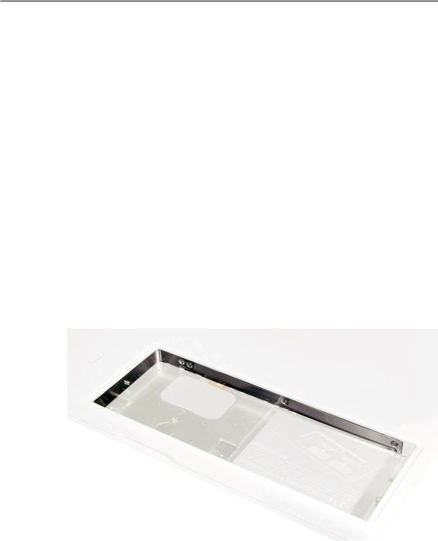
1.Follow the“Top Case”procedure in this chapter to remove the top case.
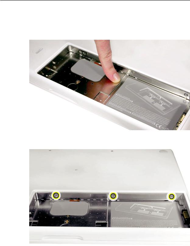
2.Notice the eject bars on each side of the memory card carrier. Use a black stick to push and slide the eject bar down the side of the carrier.
3.Repeat step 2 on the other side of the memory card carrier until the memory card pops out.
MacBook (13-inch) Take Apart — Memory 25
 Hard Drive
Tools
•ESD wrist strap and mat
•Black stick (Apple part number 922-5065) or other nonconductive nylon or plastic flatblade tool
Preliminary Steps
Before you begin, remove
•Battery
•RAM door
Part Location
MacBook (13-inch) Take Apart — Hard Drive 26
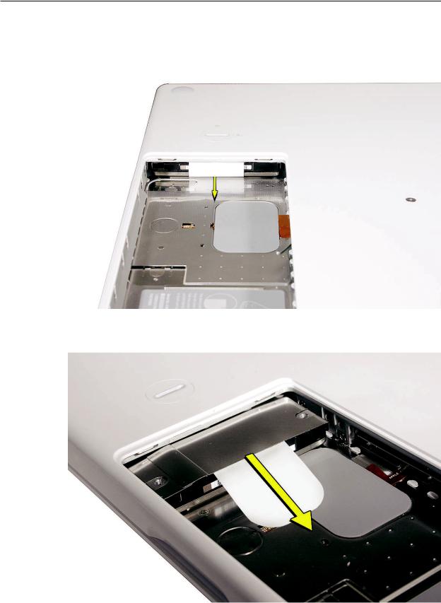
Procedure
1.If the hard drive pull-tab is tucked in, use a black stick to unroll it.
2.Pull the tab straight out to slide the drive out from the rubber rails in the battery bay.
MacBook (13-inch) Take Apart — Hard Drive 27
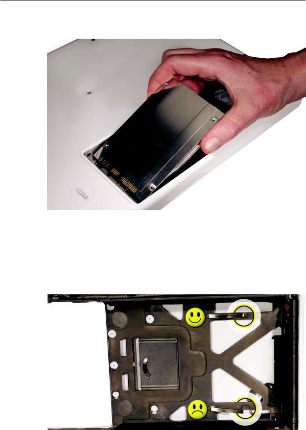
3.Hold the drive only by the sides when removing and replacing it.
4.Install the replacement hard drive, and reassemble and test the computer.
Important: After a new hard drive replacement, you must update the operating system to
Mac OS X version 10.4.6 or later.
Replacement Note: If you are installing the hard drive while the top case is off, make sure the two bottom case spring guides are aligned with the notches in the bottom case. The image below shows the top spring centered and the bottom spring off center.
MacBook (13-inch) Take Apart — Hard Drive 28
 Top Case (with Keyboard)
Tools
•ESD wrist strap and mat
•Magnetic Phillips #0 screwdriver
•Magnetic Phillips #00 screwdriver (preferably with a long handle)
•Black stick (Apple part number 922-5065) or other nonconductive nylon or plastic flatblade tool
•Access card (Apple part number 922-7172) to open the top case
•Clean, soft, lint-free cloth
Preliminary Steps
Before you begin, remove
•Battery
•RAM door
Part Location
MacBook (13-inch) Take Apart — Top Case 29
Procedure
Caution: To prevent scratches or other cosmetic damage to the computer housing, use a soft cloth as a protective layer when removing and installing the external screws.
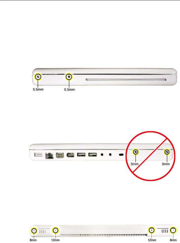
1.With the computer upright, remove the two identical 5.5-mm long shoulder screws from the right side of the computer.
Replacement Caution: When installing these top case screws, do not press on the area over the slot drive.The slot-drive bezel could be damaged with too much pressure.
2.Important: Notice the two screws at the left side of the computer. Although they can be removed, they exist for cosmetic purposes only and do not require removal. If they are removed, however, be sure to reinstall the two identical 3-mm long shoulder screws at the corner near the ports. Do not use longer screws.
3.At the back of the computer, remove the four #0 Phillips screws (two at each side) near the display hinge--
•Two 12-mm long shoulder screws that are closest to the hinge
•Two 8-mm long shoulder screws at the back corners of the computer
MacBook (13-inch) Take Apart — Top Case 30
Loading...