


 Loading...
Service Source
MacBook (13-inch)
16 May 2006
© 2006 Apple Computer, Inc. All rights reserved.

MacBook (13-inch)
Contents
Take Apart
What’s New 6 Tools 8
Temperature Concerns 9
Note About Images in This Manual 9
Battery 10
RAM Door (L-Bracket) 13
Memory (DIMMs) 17
Removal Procedure 18 Replacement Procedure 20
Hard Drive 22
Top Case (with Keyboard) 25 AirPort Extreme Card 34 MagSafe DC-In Board 37 Left Speaker 41
Battery Connector with Sleep Switch 45 Hard Drive Connector 49
Fan 55
Heatsink 58
Applying Thermal Grease 61
Bluetooth Holder 64
Optical Drive 68 Optical Drive Cable 77
I/O Frame (with upper EMI shield) 80 Logic Board 83
ii

Applying Thermal Grease 92 |
|
|
|
||||
DIMM Lever Kit |
96 |
|
|
|
|||
Backup Battery |
99 |
|
|
|
|
||
Bluetooth Antenna Board and Cable |
102 |
||||||
Bluetooth Board |
106 |
|
|
|
|||
Bluetooth-to-Logic Board Cable |
110 |
|
|||||
Subwoofer with Right Speaker Cable |
115 |
||||||
Midframe 121 |
|
|
|
|
|
||
Display Bezel |
126 |
|
|
|
|
||
Removal Procedure |
127 |
|
|
|
|||
Replacement Procedure 129 |
|
|
|
||||
C-Channel |
132 |
|
|
|
|
|
|
Clutch Block, Left |
136 |
|
|
|
|||
Clutch Block, Right |
142 |
|
|
|
|||
Clutch Caps |
146 |
|
|
|
|
||
(Refer to “Clutch Block, Left” and “Clutch Block, Right”) 146 |
|||||||
Bottom Case |
147 |
|
|
|
|
||
Display Module |
151 |
|
|
|
|||
Clutch Cover |
156 |
|
|
|
|
||
Bezel Scoops, Left and Right |
161 |
|
|||||
LCD Panel |
165 |
|
|
|
|
|
|
Antenna Receptors and Cables |
168 |
|
|||||
LCD Panel Assembly 174 |
|
|
|
||||
Removal Procedure |
176 |
|
|
|
|||
Reinstallation Procedure 180 |
|
|
|
||||
Camera Assembly |
187 |
|
|
|
|||
LVDS Cable with USB Line |
192 |
|
|||||
Microphone Cable |
197 |
|
|
|
|||
Inverter Board |
203 |
|
|
|
|||
iii

Inverter Cable 206
Display Hinges, Left and Right 209
Bezel Brace, Left 212
Bezel Brace, Right 214
Sleep Magnet 218
Display Magnet Pairs 220
Display Rear Housing 224
Troubleshooting
General Information 228
Troubleshooting Steps 229
Symptom Charts 232
Block Diagram 237
Views
Views 240
Front: Keyboard and IR Window 240
Back: Air Vents and Display Clutch 241 Left Side: Ports 241
Right Side: Slot Drive 241
Battery Bay: Memory Card Levers and Hard Drive Pull Tab 242 Top Case Removed: Main Modules and Cable Routing 242
iv
Service Source
Take Apart
MacBook (13-inch)
© 2006 Apple Computer, Inc. All rights reserved.
What’s New
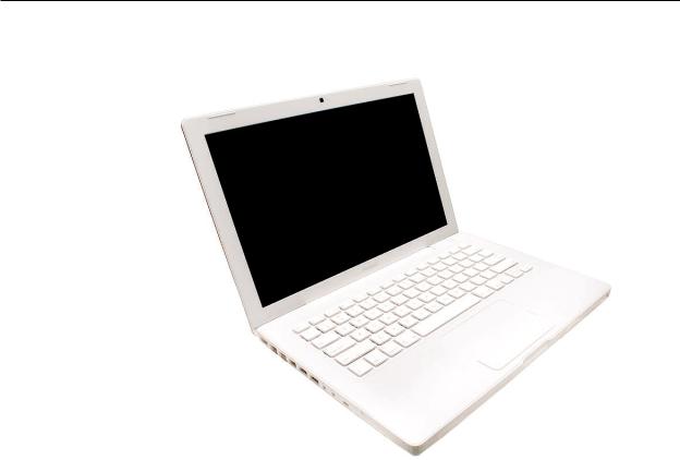
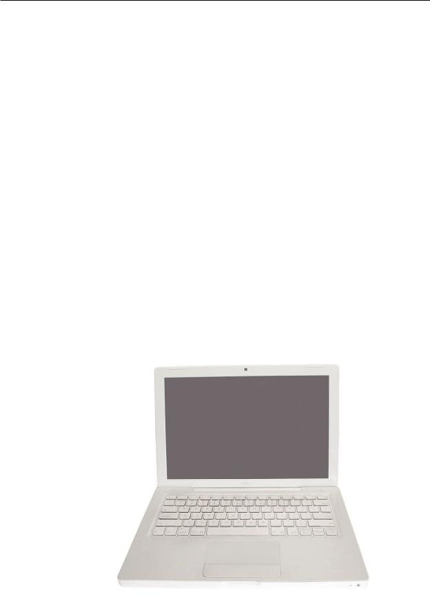
The MacBook (13-inch) portable computer is the first computer of its size featuring the Intel Core Duo processor and built-in iSight video camera.The main features and service differences (from similar-sized Apple portable computers) include:
•Higher resolution 13.3-inch LCD panel
•iSight camera built-in
•Infrared sensor on front right corner
•Hard drive is offered as a customer-replaceable module
•Digital audio-in
•MagSafe magnetic power connector
•Supports extended desktop
•Vertical-insert connectors—most of the cable connectors on the logic board use a new design that requires “straight down” insertion and “straight up” extraction
•Feet on the bottom case are heat-staked, so they are not removable
•Built-in keyboard as part of top case
•Operating temperature is hotter than previous models (refer to “Temperature Concerns” in this chapter)
MacBook (13-inch) Take Apart
The following table shows the MacBook (13-inch) model configurations at introduction:
Feature |
Good |
Better |
Best |
Intel Core Duo processor |
1.83 GHz |
2.0 GHz |
2.0 GHz |
Memory |
512 MB (x2) |
512 MB (x2) |
512 MB (x2) |
Hard Drive |
60 GB |
60 GB |
80 GB (120 GB) |
Optical Drive |
Combo, 9.5 mm |
Super, 9.5 mm |
Super, 9.5 mm |
|
|
|
|
Housing |
White |
White |
Black |
|
|
|
|
Display |
13.3-inch, 1280x800, 114 dpi, Low Reflection Glossy Polarizer (LRGP) |
||
Battery |
55-Whr Lithium Polymer |
|
|
Power Adapter |
60 W, A70, MagSafe MPM |
|
|
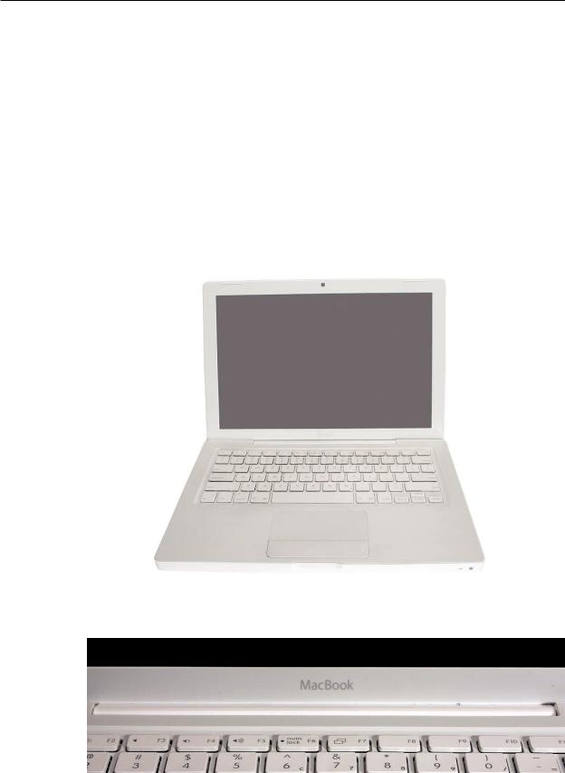
Keyboard integral to top case:
Product name on display bezel:
MacBook (13-inch) Take Apart
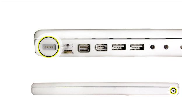
MagSafe power connector port:
Infrared window on front of computer:
For additional views of the computer, refer to the “Views” chapter at the end of this manual.
Tools
The tools required to service this computer include:
•Clean, soft, lint-free cloth
•Coin
•ESD wrist strap and mat
•Magnetic Phillips #0 screwdriver (preferably with a long handle)
•Black stick (Apple probe tool, part number 922-5065) or other nonconductive nylon or plastic flatblade tool
•Access card (Apple part number 922-7172) to open the top case
•Jeweler’s flatblade screwdriver
•Needlenose pliers
•Stack of books, weighted boxes, or other means of support for display while removing screws from hinge
•Thermal grease (Apple thermal compound syringe, part number 922-7144)
•Alcohol wipes
•Felt-tip pen (optional)
•Standard size CD or DVD disc
Power Adapter
Warning: The power adapter for this computer is unique to this model. It uses an MPM 4-pin adapter plug. Do not use this power adapter with any other portable computer. Power adapters from earlier iBook or PowerBook computers are not compatible and will not fit the MPM plug.
MacBook (13-inch) Take Apart
Temperature Concerns
This computer runs hotter than previous models. However, the normal operating temperature is well within national and international safety standards. Nevertheless, customers may be concerned about the generated heat. To prevent an unneeded repair, you can compare a customer’s computer to a running model, if available, at your repair site. For more information
on temperature concerns and customer perception, refer to Knowledge Base article 30612 “Apple Notebooks: Operating Temperature.”
http://docs.info.apple.com/article.html?artnum=30612
Note About Images in This Manual
Because a pre-production model was used for most of the images shown in this manual, you may notice small differences in appearance between the image pictured and the computer you are servicing. However, although the appearance differs, the steps and sequence are the same unless noted.
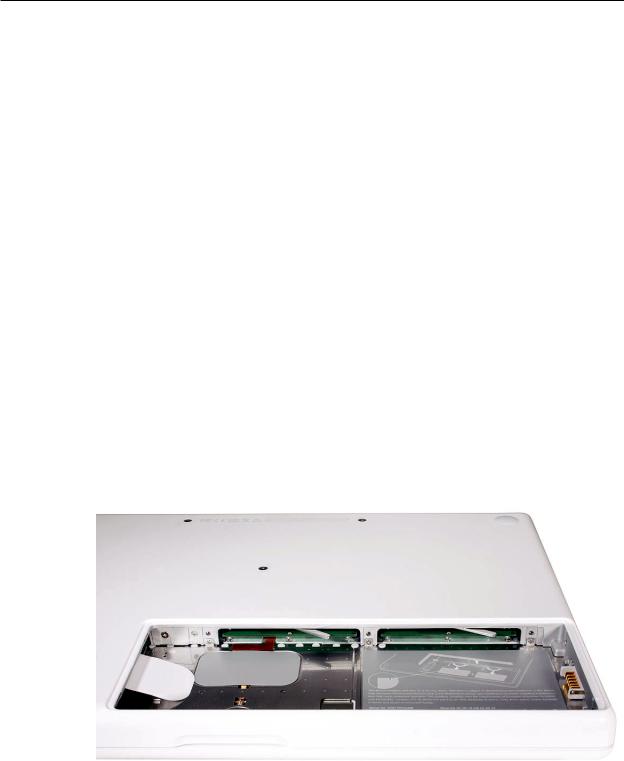
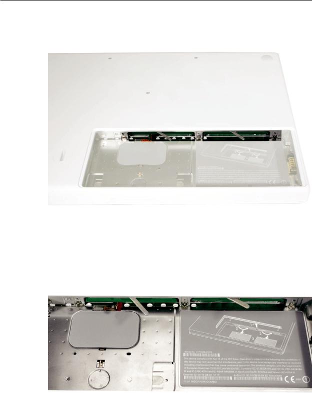
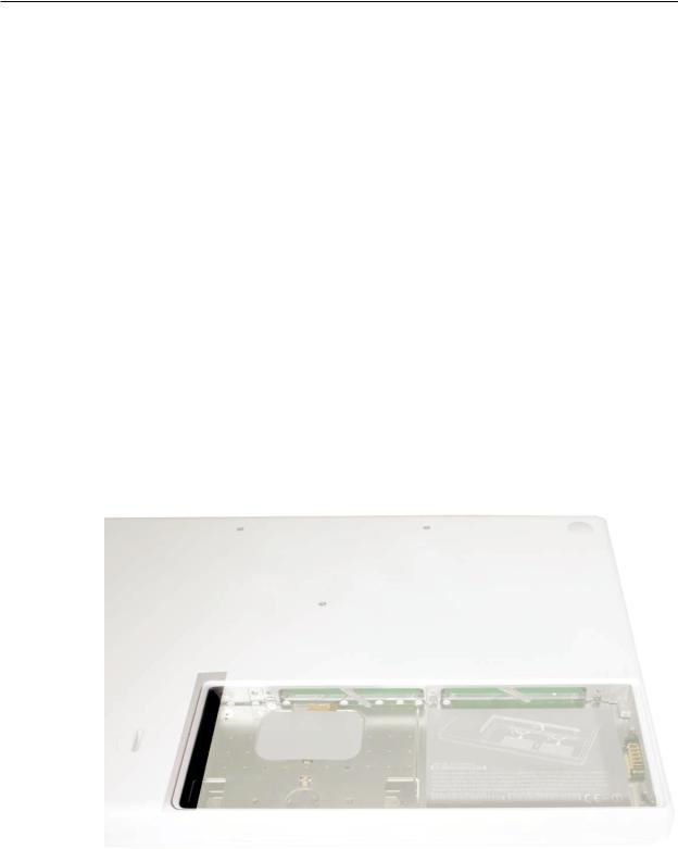
Memory Card Levers
Important: The following image shows the memory cards and hard drive installed in the battery bay. Note the correct position of the memory card levers. Some images pictured in this manual used a pre-production model, so the direction and appearance of the levers differ from the accurate depiction below. Refer to the Views chapter for other useful reference images.
MacBook (13-inch) Take Apart
 Battery
Tools
•Clean, soft, lint-free cloth
•Coin
Part Location
Preliminary Steps
Warning: Always shut down the computer before opening it to avoid damaging the internal components or causing injury. After you shut down the computer, the internal components can be very hot. Let the computer cool down for 30 minutes before continuing
MacBook (13-inch) Take Apart 10
Procedure
1.Shut down the computer.
2.Wait 30 minutes to allow the computer’s internal components to cool.
3.Unplug all external cables from the computer except the power cord.
4.Unplug the power cord.
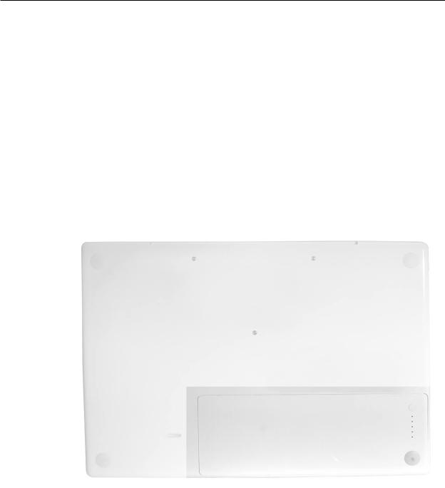
5.Put on an ESD wrist strap.
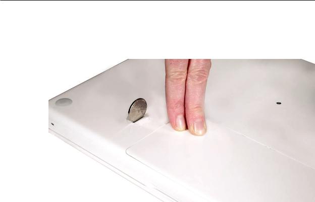
6.Turn over the computer and place it on a soft cloth. (image 0442A)
7.Use a coin to release the battery latch. Turn the coin a quarter turn clockwise to unlock the battery.
8.Lift out the battery from the battery bay.
MacBook (13-inch) Take Apart 11
9.To install the replacement battery, tilt the foot end of the battery into the battery bay first.
Then press and hold down the other end of the battery as you turn the coin to lock it into place.
10. Reassemble and test the computer.
MacBook (13-inch) Take Apart 12
 RAM Door (L-Bracket)
Tools
•Soft cloth
•ESD wrist strap and mat
•Magnetic Phillips #0 screwdriver
•Black stick (Apple part number 922-5065) or other nonconductive nylon or plastic flatblade tool
Part Location
Preliminary Steps
Before you begin, remove the battery.
MacBook (13-inch) Take Apart 13
Procedure
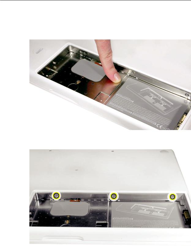
1.With the computer closed and upside down on a soft cloth, touch a metal surface inside the battery bay to discharge any static electricity.
2.Loosen—but do not try to remove—the three captive screws along the RAM door.
MacBook (13-inch) Take Apart 14
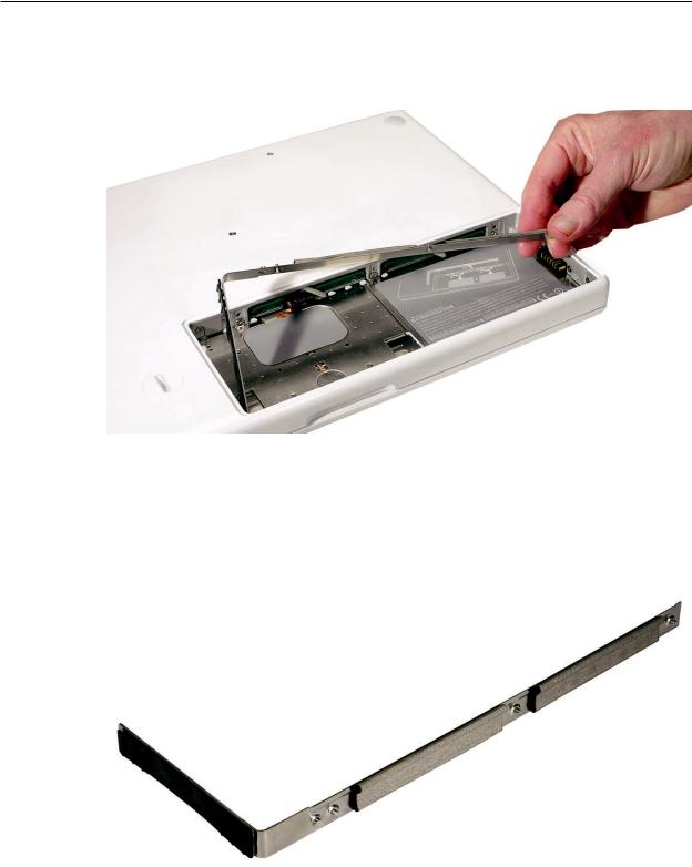
3.Holding the long end of the L-shaped RAM door, pivot it out from the battery bay. (If necessary, use a black stick to tilt it up and out of the battery bay.) Be careful not to bend it.
Replacement Note: Before replacing the RAM door, make sure that
•Hard drive pull tab is not exposed
•Cards are fully inserted
•Memory card levers are fully down before replacing the RAM door
Replacement Note: Check that the replacement RAM door has a rubber cushion to protect the hard drive opening and two EMI gaskets to protect the memory card openings.
)
MacBook (13-inch) Take Apart 15
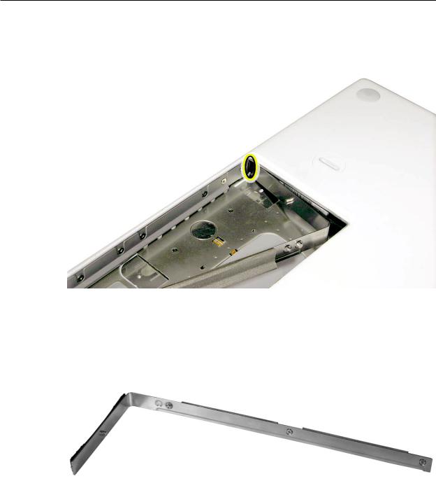
4.Replacement Note: Install the replacement RAM door by first aligning the short end at the notch near the hard drive opening.
Replacement Note: Use a black stick, if necessary, to tuck in the EMI gaskets so they do not protrude from the edge of the battery bay. Make sure the three screws align with the holes in the bottom case before tightening them.
5.Reassemble and test the computer.
MacBook (13-inch) Take Apart 16

 Memory (DIMMs)
This computer comes with a minimum of 512 MB of 667 GHz Double Data Rate 2 (DDR2)
Synchronous Dynamic Random-Access Memory (SDRAM) installed. It has two slots that can accept SDRAM Small Outline Dual Inline Memory Modules (SO-DIMMs). The slots are side-by-side on the logic board behind the RAM door. For best performance, memory should be installed
as pairs with an equal memory card in each slot. The maximum amount of memory for this computer is 2 GB, with 1GB DIMM installed in each slot.
Memory cards must meet these requirements:
•1.25 inch or smaller
•256 MB, 512 MB, or 1 GB
•200-pin
•PC-5300 DDR2 667 MHz Type RAM
Tools
•ESD wrist strap and mat
Preliminary Steps
Before you begin, remove
•Battery
•RAM door
MacBook (13-inch) Take Apart 17
Part Location
Removal Procedure
1.Touch a metal surface inside the battery bay to discharge any static electricity.
2.Put on an ESD wrist strap.
3.To eject the memory cards from the slots, move the levers all the way to the left.
MacBook (13-inch) Take Apart 18
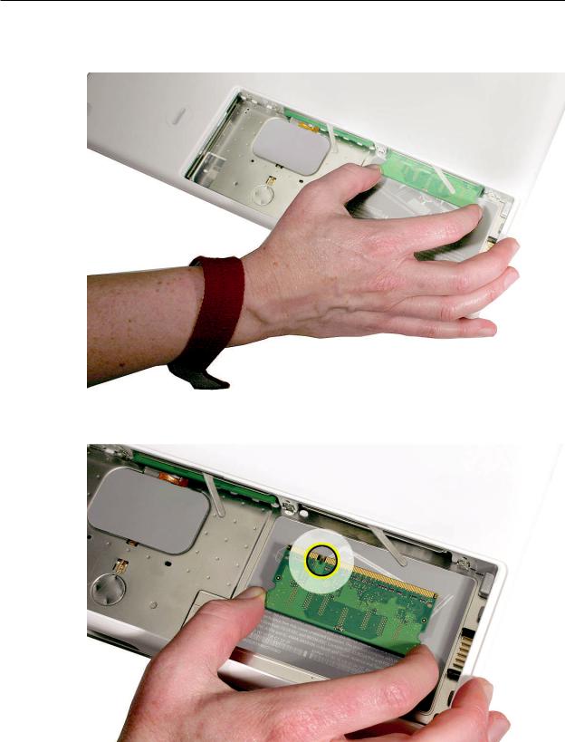
4.Holding the memory cards by the corners, slide them out from the battery bay.
Important: Do not touch the gold connectors. Handle the card only by its edges.
MacBook (13-inch) Take Apart 19
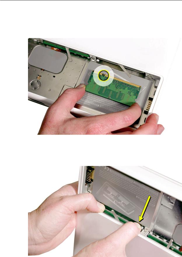
Replacement Procedure
1.Align the memory card so that the gold connectors face the slot and the notch is on the left. (The chip side of the board faces down.)
2.Use two fingers to push firmly on the edge of the memory cards. If there is a tight fit, installing the cards may take some force to ensure that they are fully inserted.
MacBook (13-inch) Take Apart 20
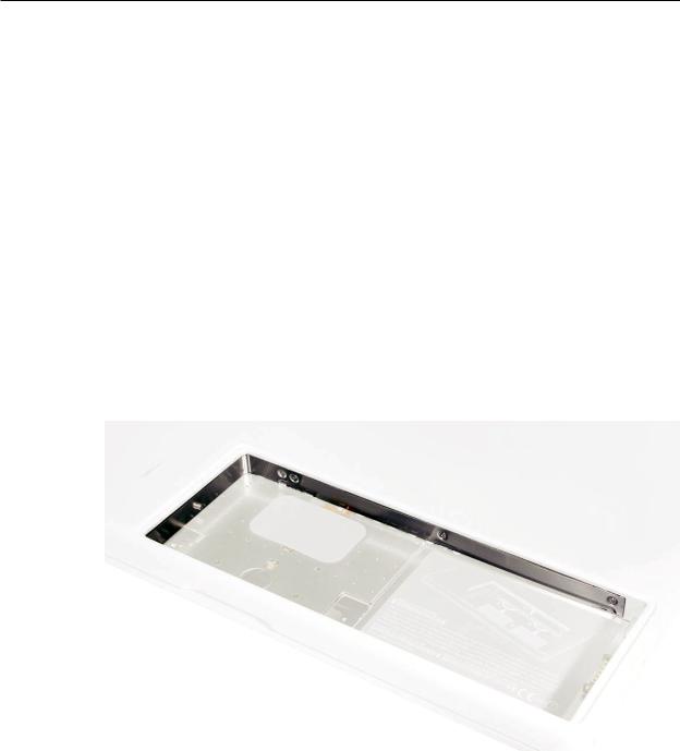
Important: When the cards are fully inserted, the edges of the cards are hidden, as shown by the recessed card on the left in the image below.
3.If the levers do not return to the closed position, move them to close them.
4.Reassemble and test the computer.
5.Make sure the computer recognizes the new memory by opening System Profiler, clicking
More Info, and clicking Memory.
MacBook (13-inch) Take Apart 21
 Hard Drive
Tools
•ESD wrist strap and mat
•Black stick (Apple part number 922-5065) or other nonconductive nylon or plastic flatblade tool
Preliminary Steps
Before you begin, remove
•Battery
•RAM door
Part Location
MacBook (13-inch) Take Apart 22
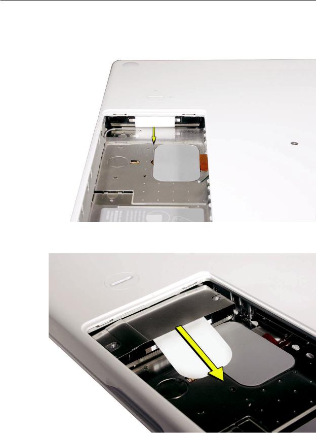
Procedure
1.If the hard drive pull-tab is tucked in, use a black stick to unroll it.
2.Pull the tab straight out to slide the drive out from the rubber rails in the battery bay.
MacBook (13-inch) Take Apart 23
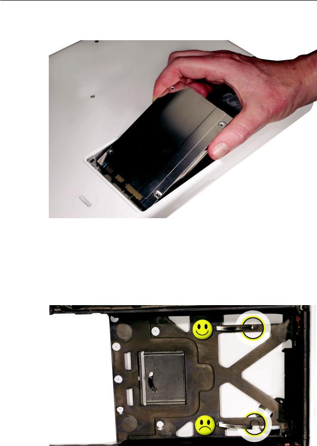
3.Hold the drive only by the sides when removing and replacing it.
4.Install the replacement hard drive, and reassemble and test the computer.
Important: After a new hard drive replacement, you must update the operating system to Mac OS X version 10.4.6 or later.
Replacement Note: If you are installing the hard drive while the top case is off, make sure the two bottom case spring guides are aligned with the notches in the bottom case. The image below shows the top spring centered and the bottom spring off center.
MacBook (13-inch) Take Apart 24
 Top Case (with Keyboard)
Tools
•ESD wrist strap and mat
•Magnetic Phillips #0 screwdriver (preferably with a long handle)
•Black stick (Apple part number 922-5065) or other nonconductive nylon or plastic flatblade tool
•Access card (Apple part number 922-7172) to open the top case
•Clean, soft, lint-free cloth
Preliminary Steps
Before you begin, remove
•Battery
•RAM door
Part Location
MacBook (13-inch) Take Apart 25
Procedure
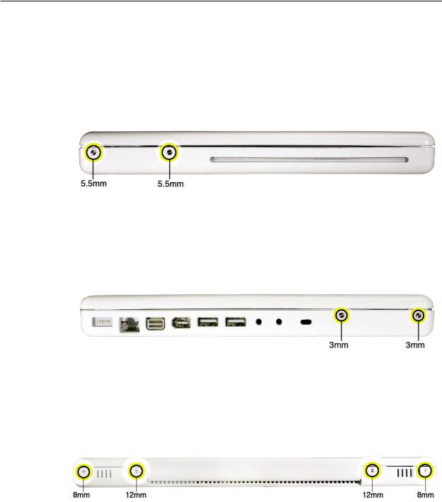
1.With the computer upright, remove the two identical 5.5-mm long shoulder screws from the right side of the computer.
Replacement Caution: When installing these top case screws, do not press on the area over the slot drive.The slot-drive bezel could be damaged with too much pressure.
2.Important: Notice the two screws at the left side of the computer. Although they can be removed, they exist for cosmetic purposes only and do not require removal. If they are removed, however, be sure to reinstall the two identical 3-mm long shoulder screws at the corner near the ports. Do not use longer screws.
(image 0434A)
3.At the back of the computer, remove the four #0 Phillips screws (two at each side) near the display hinge--
•Two 12-mm long shoulder screws that are closest to the hinge
•Two 8-mm long shoulder screws at the back corners of the compute
MacBook (13-inch) Take Apart 26
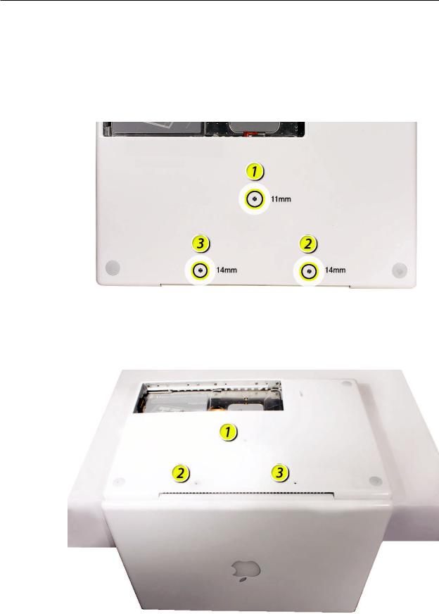
4.Turn over the computer, and on the outside of the bottom case, remove the three #0 Phillips screws:
•Two 14-mm long screws near display hinge
•One 11-mm long at center of bottom case
Replacement Caution: Do not put one of the longer screws in the center screw hole or it will damage the logic board.
Replacement Caution: When installing the three bottom case screws, the LCD panel can be damaged if the display is closed. Make sure you open the display to a 90-degree angle and place the display upside down over a cloth-draped table edge so that the display and keyboard are protected. Then install the screws in the order shown.
MacBook (13-inch) Take Apart 27
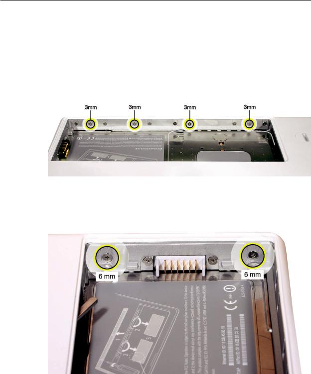
5.Notice the long row of #0 Phillips screws at the front edge of the battery bay.
. Important: Remove only the four screws shown. Remove the 3-mm long identical screws as follows:
Starting at the corner closest to the battery connector, skip the first screw, then remove the second, fourth, seventh, and ninth screw.
Tip: To help remember the screw sequence, think of it as “2, 4, 7, 9 loosens the top case every time.”
7.In the battery bay, remove the two 6-mm long identical screws that are on both outer sides of the battery connector. Do not remove the two screws that are closest to the battery connector.
MacBook (13-inch) Take Apart 28
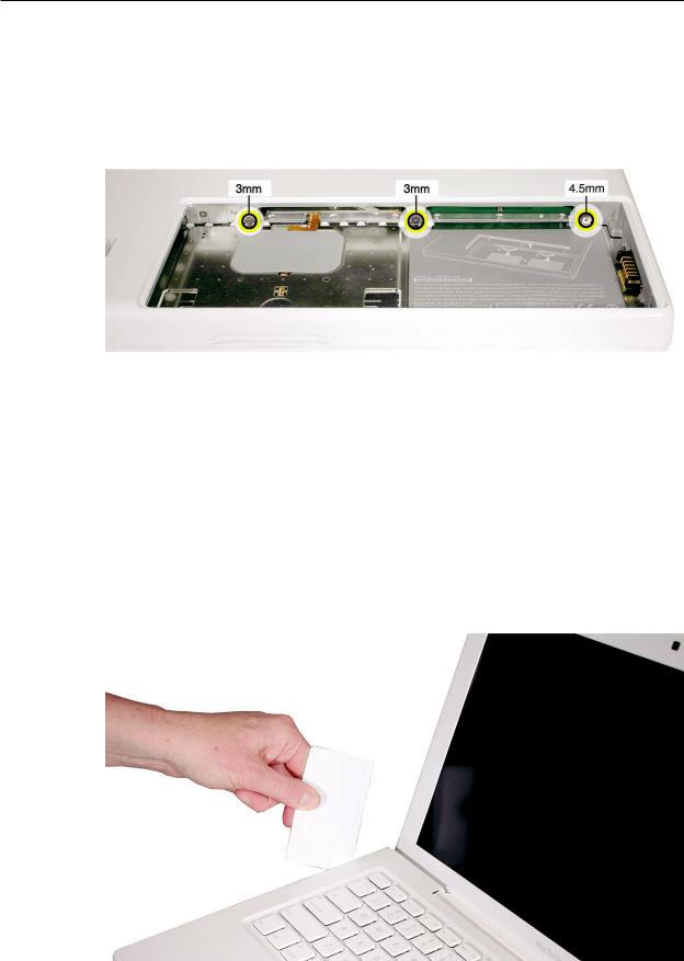
8.In the battery bay, use a long-handled screwdriver to remove the three screws at the inner edge of the battery bay near where the RAM slots are located:
•Two identical 3-mm long screws
•One longer 4.5-mm long screw at the corner of the battery bay nearest the battery connector
Because this is a recessed area, the screwdriver has to go in at an angle. Keep the screwdriver in line with the screw head as much as possible.
Replacement Caution: When installing these three screws, an incorrect installation could cause the reassembled computer to wobble in use. To prevent a wobble symptom, use light pressure to hold the top case onto the assembly when installing the screws.
9.Open the display to a 90-degree angle or wider.
10.Warning: Inserting a tool too far or performing this step too quickly could break some of the snaps that secure the top case. Be especially careful with the left front corner of the top case. Starting at the left corner and working in a counter-clockwise direction, use an access card tool to open the gap along the front of the top case, around the perimeter, and to the right side above the optical drive slot.
MacBook (13-inch) Take Apart 29
 06-05 Service Manual")
11.With the top and right side gap opened, tilt up—but do not remove—the right edge of the top case. This motion releases the remaining snaps between the top case and bottom case.
12.Raise up the top case so you can see where the folded trackpad flex cable attaches to the logic board.
MacBook (13-inch) Take Apart 30
Loading...