


K Service Source
Envelope Feeder
LaserWriter Pro 600/630 Envelope Feeder
LaserWriter 16/600 PS Envelope Feeder

K Service Source
Basics
Envelope Feeder
Basics |
About This Manual - 1 |
|
|
About This Manual
This manual covers the Take Apart, Additional Procedures, and Adjustments for the sheet feeder. Refer to the main printer manuals for all other information.
Envelope Feeder

Basics |
Compatibility - 2 |
|
|
Compatibility
The LaserWriter Pro 600/630 envelope feeder is compatible only with the Pro 600/630 printer. However, you may use the LaserWriter 16/600 PS envelope feeder with either the Pro 600/630 or 16/600 printers.
You can tell the two feeders apart in three distinct ways:
1By carefully inspecting the pickup rollers and shafts: The LaserWriter Pro 600/630 model has a two-piece roller/shaft construction. The LaserWriter 16/600 PS model has a one-piece roller/shaft construction.

Basics |
Compatibility - 3 |
||
|
|
||
|
2 By comparing controller board serial numbers: The |
||
|
LaserWriter Pro 600/630 envelope feeder controller |
||
|
board has the vendor number "RG5-0576" imprinted at |
||
|
the end of the board. The LaserWriter 16/600 PS |
||
|
envelope feeder controller board bears the number |
||
|
"RG1-3437." |
||
|
3 By comparing serial numbers: Numbers starting with |
||
|
JXC00001 denote feeders for use only with the Pro |
||
|
600/630. Numbers starting with LBK00001 denote |
||
|
feeders for use on both generations of printer. |
||
|
|
|
|
|
|
|
|

 Basics Slip Torque Rollers - 4
|
Slip Torque |
1/4" ± |
Rollers |
|
Slip torque rollers and gears |
|
are ratcheted torque- |
|
limiting gears that use |
|
bearings instead of teeth to |
|
govern rotation: |
Shaft |
|
Roller or Gear

Basics |
Slip Torque Rollers - 5 |
||
|
|
||
|
Primary Feed Roller: |
||
|
This roller acts independently of the shaft when the roller is |
||
|
rotated in reverse, thus permitting free removal of jams. |
||
|
Separation Drive Assembly: |
||
|
The gearing at the end of the separation assembly is |
||
|
comprised of one passive gear and two slip torque gears. |
||
|
This assembly results in counter-rotation of the separation |
||
|
rollers, regardless of the drive direction of the gear train. |
||
|
Pickup Roller Shafts: |
||
|
The two gears that mesh with the transfer drive assembly |
||
|
are slip torque gears. |
||
|
|
|
|
|
|
|
|

K Service Source
Take Apart
Envelope Feeder
Take Apart |
Envelope Weight - 1 |
|
|
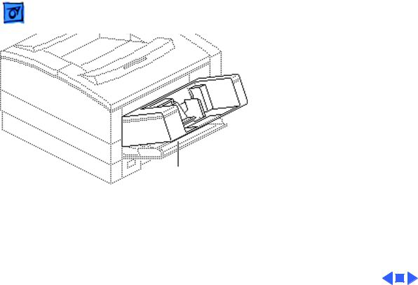
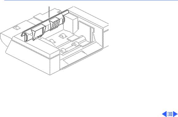
Envelope Weight
No preliminary steps are Envelope Weight required before you begin
this procedure.
1 Pull one of the arms out of the pin and lift out the weight.
Take Apart |
Left Cover - 2 |
|
|
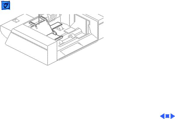
Left Cover
Before you begin, remove the envelope weight.
Left Cover
Take Apart |
|
Left Cover - 3 |
|
|
|
|
|
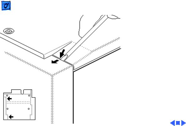
Note: Two hidden flex tabs |
|
|
on the bottom and two posts |
|
|
at the top attach the left |
|
|
cover to the feeder. |
|
|
1 Turn over the envelope |
|
Bottom |
feeder. |
|
|
|
|
|
2 Using a small flat-blade |
|
|
screwdriver, pry the |
|
|
two hidden tabs in the |
|
|
order shown and remove |
|
|
the left cover. |
Left Cover
Bottom
Take Apart |
Right Cover - 4 |
|
|
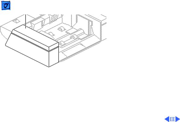
Right Cover
Right Cover
Before you begin, remove the envelope weight.
|
Take Apart |
Right Cover - 5 |
|
|
|
|
|
|
|
Note: Two hidden flex tabs |
|
|
|
on the bottom and two posts |
|
|
|
at the top attach the right |
|
|
Bottom |
cover to the feeder. |
|
|
|
1 Turn over the envelope |
|
|
|
feeder. |
|
|
|
2 Using a small flat-blade |
|
|
|
screwdriver, pry the |
|
|
|
two hidden tabs in the |
|
Right Cover |
order shown and remove |
||
the right cover. |
|||
|
|
||
Bottom
 Take Apart Front Cover - 6
|
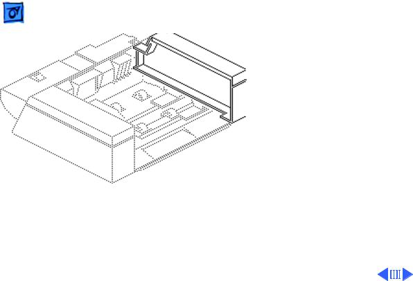
Front Cover |
Front Cover |
Before you begin, remove |
|
the following: |
|
• Envelope weight |
|
• Left cover |
|
• Right cover |
|
Note: If you remove the |
|
separation guide plate from |
|
the front cover, you will |
|
have to adjust the gap |
|
between the separation guide |
|
plate and the primary feed |
|
roller. See "Separation |
|
Guide Opening" in |
|
Adjustments. |

Take Apart |
|
Front Cover - 7 |
|
|
|
Flex Tab |
1 Remove the screw that |
|
|
secures the grounding |
|
|
|
|
|
|
cable that runs from the |
|
|
front cover (not shown). |
|
2 |
Note: This graphic |
|
|
shows the flex tab |
|
|
connector at the left side |
|
|
of the feed opening. |
Release the two flex tab connectors at each side of the feed opening and pull out the front cover.
 Loading...