


K Service Source
LaserWriter 10/600 A3+
This printer is an Asia-only product.

Table of Contents
Section 1 Introduction
Section 2 Specifications
Section 3 Parts Lists
Section 4 Removal and Replacement Procedures (RRP) Section 5 Principle of Operation
Section 6 General Procedures and Information
Section 7 Fault Isolation Procedures
Section 8 Installation and Removal

LaserWriter 10/600 A3+
Section 1
Introduction
Section Contents
1.About This Manual
1.1How This Manual Is Organized . . . . . . . . . . . . . . . . . . . . . . . . . . . . . 1-1
1.2Revision . . . . . . . . . . . . . . . . . . . . . . . . . . . . . . . . . . . . . . . . . 1-2
1.3 Notational Conventions . . . . . . . . . . . . . . . . . . . . . . . . . . . . . . . . . 1-2
1.4OEM-Specific Specifications. . . . . . . . . . . . . . . . . . . . . . . . . . . . . . . 1-2
1.5Abbreviations. . . . . . . . . . . . . . . . . . . . . . . . . . . . . . . . . . . . . . . 1-3
2.Associated Documents . . . . . . . . . . . . . . . . . . . . . . . . . . . . . . . 1-3
3.Safety Information
3.1Safety Components. . . . . . . . . . . . . . . . . . . . . . . . . . . . . . . . . . . . 1-4
3.2Laser Beam. . . . . . . . . . . . . . . . . . . . . . . . . . . . . . . . . . . . . . . . 1-4
3.3Power . . . . . . . . . . . . . . . . . . . . . . . . . . . . . . . . . . . . . . . . . . . 1-5
3.4Driving Sections . . . . . . . . . . . . . . . . . . . . . . . . . . . . . . . . . . . . . 1-5
3.5 High Temperature Sections |
. |
. |
. |
. |
. |
. |
. |
. |
. |
. |
. |
. |
. |
. |
. |
. |
. |
. |
. |
. |
. |
. |
. |
. |
. |
. |
. |
. |
. |
. |
. 1-6 |
3.6 Warning / Caution Labels . |
. |
. |
. |
. |
. |
. |
. |
. |
. |
. |
. |
. |
. |
. |
. |
. |
. |
. |
. |
. |
. |
. |
. |
. |
. |
. |
. |
. |
. |
. |
. 1-6 |
3.6.1Laser Warning Label . . . . . . . . . . . . . . . . . . . . . . . . . . . . . . . 1-6
3.6.2High Temperature Caution Label. . . . . . . . . . . . . . . . . . . . . . . . . 1-7
3.6.3 High Voltage Caution Label . . . . . . . . . . . . . . . . . . . . . . . . . . . 1-7

Introduction — LaserWriter 10/600 A3+ |
1 – 1 |
1. ABOUT THIS MANUAL
This document serves as a standard service manual of Fuji Xerox Co., Ltd, which contains the knowledge and information for the maintenance of this printer.
This document was prepared for OEM customers of Fuji Xerox either as a service manual or as material for preparing their own service manuals of this printer. Other uses of this document are prohibited.
No portion of this document may be reproduced or used for other purposes without prior consent of Fuji Xerox.
1.1 How This Manual Is Organized
This manual has eight sections. The contents of the sections are briefly explained below;
Section 1 Introduction describes general information on this manual such as the organization of this manual, related documents, and safety information.
Section 2 Specifications describes the specifications of this printer, consumable, periodic replacement parts, and the optional devices.
Section 3 Parts List shows the exploded drawings of the printer with lists of the part names.
Section 4 Removal and Replacement Procedures (RRP) explains the procedures for the removal and replacement of parts.
Section 5 Principles of Operation describes the basic information of this printer such as print process and the functions of the major components of the printer.
Section 6 General Procedures and Information describes the functions for giving assistance in locating the cause of trouble and the operations for using them, and also provides useful information for troubleshooting such as the location of the connector (plug/jack) and electrical wiring.
Section 7 Fault Isolation Procedures explains the procedures for analysis of trouble to resolve it and the maintenance information.
Section 8 Installation and Removal explains the installation and removal of the printer.
Introduction — LaserWriter 10/600 A3+ |
1 – 2 |
1.2 Revision
The revision of this manual is made in the following manner, and the revised manual is sent when revisions are made.
(Method of Revision)
sWhen the entire manual is subject to be revised, the issue number printed on the cover is increased as Issue 1, Issue 2, Issue 3 and so on.
s Partial revision is made by pages.
sRevised new pages replace old pages or are added to the manual. The modified, added or deleted parts on the revised pages are clearly indicated with a black bar called "change bar".
| :This mark is put at the left of the modified, added or deleted parts in the text.
sWhen a previously revised page is revised again, the change bars of the previous revision are deleted, and the parts altered by the latest revision are indicated with new change bars.
1.3 Notational Conventions
The following terms are used to indicate the notes during maintenance or added information for the text.
Warning : Indicates an operating or maintenance procedure, if not strictly observed, it could result in injury or loss of life.
Caution : Appears before a procedure or work which, if not observed, could result in personal injury or destruction of equipment.
Note : Emphasizes specific procedure, work, rule, and so on.
Memo : Contains additional information set off from the text.
1.4 OEM-Specific Specification
The OEM customer specific specifications are described on separate pages added after the this manual.

Introduction — LaserWriter 10/600 A3+ |
1 – 3 |
1.5 Abbreviations
This manual contains general and other abbreviations specific for this manual as follows;
ASSY = Assembly |
AUX = Auxiliary |
BCR = Bias Charge Roll |
BTR = Bias Transfer Roll |
CM Blade = Charging & Metering Blade |
CR = Charge Roll |
CRU = Customer Replaceable Unit |
CST = Cassette |
DB = Development Bias |
dpi = Dots per inch |
DTS = Detack Saw |
ELEC. = Electric |
EP = Electrophotography |
ESS = Electronic Subsystem |
H/R = Heat Roll |
HVPS = High Voltage Power Supply |
I/F = Interface |
LD = Laser Diode |
LVPS = Low Voltage Power Supply |
MCU = Machine Control Unit |
MSI = Multi Sheet Inserter |
N/F = Normal Force |
N/P = No Paper |
OPC = Organic Photo Conductor |
P/H = Paper Handling |
P/R = Pressure Roll |
PPM = Prints Per Minute |
PWB = Printed Wiring Board |
REGI. = Registration |
ROS = Raster Output Scanner |
SOS = Start Of Scan |
TEMP. = Temperature |
TR = Transfer Roll |
TRANS. = Transport |
|
|
2. Associated Documents
There are documents associated with this manual as follows;
sOperator Manual (Standard Manual)
Describes the operation and handling of this printer.
sPerformance Specifications
Contains the detailed specifications of this printer.
(If some contents of this manual do not agree with the Performance Specifications, follow the Performance Specifications.)
sVideo Interface Specifications
Describes the video interface specifications of this printer.
sSpare Parts List
Provides the information on the spare parts of this printer.
Introduction — LaserWriter 10/600 A3+ |
1 – 4 |
3. Safety Information
To prevent an accident while working on the printer, strictly observe warnings and cautions described in this manual.
Never conduct dangerous operations or operations not in this manual.
There may be several dangerous things other than those described below, always work with extreme caution for safety reasons.
3.1 Safety Components
This printer has safety components to protect from accidents to occur (fuse, thermostat, interlock switches and so on) and safety component for user operation (cover, panel and so on). They must be kept in their operational state.
Never modify the printer (especially of the safety components).
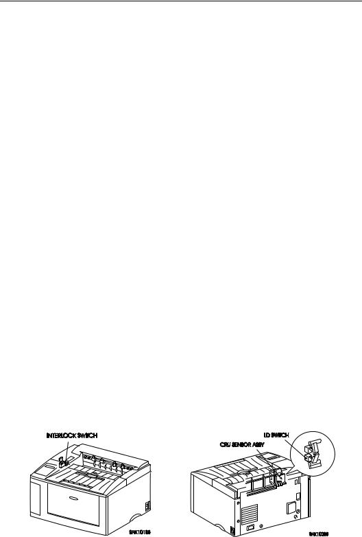
3.2 Laser Beam
To avoid exposure to the laser beam, this printer is equipped with the two safety switches; Interlock Switch and CRU Switch in the CRU Sensor Assembly. The Interlock Switch turns OFF when opening covers and stops supply of the power. The CRU Switch cuts the circuit when the EP Cartridge is removed and stops power supply to the circuit of the output of the laser beam.
Caution : 1. Direct eye exposure to the laser beam may cause eye injury or blindness.
2.Never open the covers in which a warning label on the laser beam is sealed.
3.Switch OFF the printer power when you perform removal and reinstallation of the printer.
4.Be sure to follow the procedure described in this manual when you work on the printer during its operation.
5.Remove the EP Cartridge before you press the Interlock Switch by hand or tools during maintenance operation. (Do not turn on the Interlock Switch and CRU Switch at the same time.)
6.Recognize the character of the laser beam and the dangers that are involved that can inflict harm to the human body, and take precaution when handling the laser beam in order to avoid injury to you and those around you.
Note : The laser beam is characterized by a very small range of wave lengths and the similar phase of waves, in contrast with other light (the light of the sun and that of an electric lamp, for example). Therefore, the laser beam is monochromatic and has a high focusability, and can reach long distance in a thin beam. The thin laser beam has a very high energy density and high temperature and can inflict injury to the human body.
Memo : The laser beam used for this printer is invisible and you cannot see it.

Introduction — LaserWriter 10/600 A3+ |
1 – 5 |
3.3 Power
When working on the printer, be sure to switch off the printer power and unplug the power cord to avoid electric shock, burn or injury.
When it is necessary to work with the power on such as when measuring the voltage, conduct the work with great care to avoid an electric shock and follow the procedures described in this manual.
Warning : Do not touch live parts other than those necessary to do so when working on the printer when power on.
The power switch/inlet section (LVPS Assembly) is supplied with power even if the power is switched OFF, therefore never touch the live parts.
3.4 Driving Sections
When working on the driving sections such as gears, to avoid injury, make sure to switch the power OFF, disconnect the power cord, and rotate gears by hand (hand crank).
Warning : Never touch the gears while the printer is in operation.

Introduction — LaserWriter 10/600 A3+ |
1 – 6 |
3.5 High Temperature Sections
When working on the high temperature sections such as fuser component, to avoid burn or injury, make sure to switch the power OFF, disconnect the power cord, and begin to work after the temperature of the component has gone down significantly.
Caution : The temperature is high just after the printer operates, therefore begin to work after letting the component cool down.
3.6 Warning / Caution Labels
Warning and caution labels are sealed on dangerous parts in the printer to warn and prevent accident.
Check whether these labels are firmly sealed in place and are not soiled when performing maintenance or repair.
3.6.1 Laser Warning Label
To avoid direct exposure of the laser beam to the engineer, a laser warning label is sealed on top of the laser output unit (ROS Assembly).
Introduction — LaserWriter 10/600 A3+ |
1 – 7 |
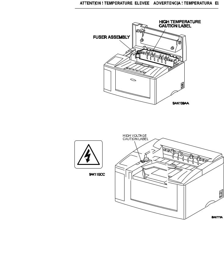
3.6.2 High Temperature Caution Label
To avoid burn of customers, caution labels are sealed on top of the fuser unit (Fuser Assembly).
3.6.3 High Voltage Caution Label
To reduce the risk of electric shocks to the engineer, caution labels are sealed on top of the frame (Main Frame Assembly) which is on top of the high voltage power supply (HVPS)
.
LaserWriter 10/600 A3+
Section 2
Specifications
Section Contents
1. Specifications
1.1 Configuration . . . . . . . . . . . . . . . . . . . . . . . . . . . . . . . . . . . . . .2-1
1.1.1Basic Configuration . . . . . . . . . . . . . . . . . . . . . . . . . . . . . . . .2-1
1.1.2Functional Configuration . . . . . . . . . . . . . . . . . . . . . . . . . . . . .2-1
1.2Functional Specifications . . . . . . . . . . . . . . . . . . . . . . . . . . . . . . . . .2-2
1.2.1Method of Printing . . . . . . . . . . . . . . . . . . . . . . . . . . . . . . . .2-2
1.2.2 Method of Exposing . . . . . . . . . . . . . . . . . . . . . . . . . . . . . . .2-2
1.2.3Method of Fusing . . . . . . . . . . . . . . . . . . . . . . . . . . . . . . . . .2-2
1.2.4Continuous Printing Speed . . . . . . . . . . . . . . . . . . . . . . . . . . . .2-2
1.2.5Resolution. . . . . . . . . . . . . . . . . . . . . . . . . . . . . . . . . . . . .2-2
1.2.6 Warm-up Time . . . . . |
. . . . . . . . . . . . . . . . . . . . . . . . . . . . .2-3 |
1.2.7 Maximum Paper Size . . |
. . . . . . . . . . . . . . . . . . . . . . . . . . . . .2-3 |
1.2.8 Maximum Printing Area |
. . . . . . . . . . . . . . . . . . . . . . . . . . . . .2-3 |
1.2.9Maximum Paper held in Output Tray . . . . . . . . . . . . . . . . . . . . . . .2-3
1.2.10Means for Feeding Paper . . . . . . . . . . . . . . . . . . . . . . . . . . . .2-3
1.2.11Maximum Sheets of Feeding Paper . . . . . . . . . . . . . . . . . . . . . . .2-3
1.2.12Paper Weight Limitations . . . . . . . . . . . . . . . . . . . . . . . . . . . .2-4
1.2.13Types of Paper . . . . . . . . . . . . . . . . . . . . . . . . . . . . . . . . . .2-4
1.2.14 |
Standard Paper |
. |
. |
. |
. |
. |
. |
. |
. |
. |
. |
. |
. |
. |
. |
. |
. |
. |
. |
. |
. |
. |
. |
. |
. |
. |
. |
. |
. |
. |
. |
. |
. |
.2-4 |
1.2.15 |
Paper Size . |
. . |
. |
. |
. |
. |
. |
. |
. |
. |
. |
. |
. |
. |
. |
. |
. |
. |
. |
. |
. |
. |
. |
. |
. |
. |
. |
. |
. |
. |
. |
. |
. |
.2-4 |
1.3Electric Specifications . . . . . . . . . . . . . . . . . . . . . . . . . . . . . . . . . .2-6
1.3.1Power Source . . . . . . . . . . . . . . . . . . . . . . . . . . . . . . . . . . .2-6
1.3.2 Power Consumption . . . . . . . . . . . . . . . . . . . . . . . . . . . . . . .2-6
1.4Mechanical Specifications . . . . . . . . . . . . . . . . . . . . . . . . . . . . . . . .2-6
1.4.1Dimensions and Weight. . . . . . . . . . . . . . . . . . . . . . . . . . . . . .2-6
1.4.2Space Requirements (Minimum Installation Space) . . . . . . . . . . . . . . .2-6
1.5Operating Environment . . . . . . . . . . . . . . . . . . . . . . . . . . . . . . . . . .2-7
1.5.1Temperature & Humidity . . . . . . . . . . . . . . . . . . . . . . . . . . . . .2-7
1.5.2Altitude . . . . . . . . . . . . . . . . . . . . . . . . . . . . . . . . . . . . . .2-7
1.5.3Horizontal Bias . . . . . . . . . . . . . . . . . . . . . . . . . . . . . . . . . .2-7
1.5.4Noise(when the front tray is closed) . . . . . . . . . . . . . . . . . . . . . . .2-7
1.6Printing Accuracy. . . . . . . . . . . . . . . . . . . . . . . . . . . . . . . . . . . . .2-7

LaserWriter 10/600 A3+
Section 2
Specifications
2.Consumable . . . . . . . . . . . . . . . . . . . . . . . . . . . . . . . . . . . . . . . 2-8
3.Parts which require Periodical Replacement . . . . . . . . . . . . . . 2-8

Specifications — LaserWriter 10/600 A3+ |
2 – 1 |
1. Specifications
1.1 Configuration
1.1.1 Basic Configuration
The LaserWriter 10/600 A3+ laser printer has two types of configurations;
•Basic configuration 1 = Base engine + EP cartridge
•Basic configuration 2 = Base engine + EP cartridge + Paper feeder + Paper cassette
Note: The basic configuration 2 includes options.
1.1.2 Functional Configuration
Functional configuration of this printer consists of the engine, controller, and control panel.
Specifications — LaserWriter 10/600 A3+ |
2 – 2 |
1.2 Functional Specifications
1.2.1 Method of Printing
Electrophotographic printing
1.2.2 Method of Exposing
Scanning done by light beam of a semiconductor laser
1.2.3 Method of Fusing
Fusing by heat and pressure
1.2.4 Continuous Printing Speed |
|
|
The speed of printing varies depending on the size of paper. |
|
|
• |
LETTER(LEF), A4(LEF), EXECUTIVE(LEF), B5(LEF), A5(LEF), |
|
|
STATEMENT(LEF), Postcard(SEF), MONARCH(SEF) ....................................... |
10.3PPM |
• A4(SEF), LETTER(SEF), B5(SEF), C5(SEF), COM-10(SEF), DL(SEF) ............... |
8.1PPM |
|
• |
B4(SEF), LEGAL14"(SEF), LEGAL13"(SEF) ........................................................ |
6.8PPM |
• |
LEDGER(SEF), A3(SEF).......................................................................................... |
5.9PPM |
•Nonstandard size
The speed of printing determined by the specification of the nonstandard size paper is as follows :
Nonstandard size 1 : 5.2PPM
Nonstandard size 2 : 3.0PPM
Note : 1. The specification for nonstandard size is determined by the OEM contract with Fuji Xerox.
The nonstandard size 1 is standard specification, and the nonstandard size 2 is a special optional specification which is usually not available.
2.SEF is the abbreviation for Short Edge Feed which means feeding of paper with the short edge (side) facing the front, and LEF for Long Edge Feed which means feeding of paper with the long edge (side) facing the front.
When neither SEF nor LEF is indicated, the orientation of paper is SEF.
Memo : PPM stands for Prints Per Minute, that is, the number of paper sheets the printer can print per minute.
1.2.5Resolution
•600 dpi (23.62 dot/mm)
Memo : "dpi" is the abbreviation of dots per inch, that is, the number of dots per inch.
Specifications — LaserWriter 10/600 A3+ |
2 – 3 |
1.2.6 Warm-up Time
The warm-up time consists of the time from when the printer power is turned on to when the printer is ready to print.
Within 65 seconds when the nominal voltage is applied.
Memo : The Main Motor will start to rotate when the warm-up begins and will stop when the warm-up is completed.
1.2.7 Maximum Paper Size
•For standard paper, maximum printable paper size is either LEDGER or A3.
•For nonstandard size paper, maximum printable paper size is selected by the specification as follows (provided that only printing operation is possible);
Nonstandard size 1 : Max. 297.0mm x 508.0 mm
Nonstandard size 2 : Max 297.0mm x 900.00mm
Note : The specification for nonstandard size is determined by the OEM contract with Fuji
Xerox. The nonstandard size 1 is standard specification, and the nonstandard size 2 is special optional specification which is usually not available.
1.2.8 Maximum Printing Area
4.0 millimeters in from all four sides of the standard paper.
1.2.9 Maximum Paper held in Output Tray
250 sheets of A4 Fuji Xerox standard paper type L at the ambient temperature of 22 oC and humidity of 55%RH.
1.2.10 Means for Feeding Paper
This printer has two types of paper feeds :
•Front tray feeding
Multi-sheet manual feeding from the front tray at the front of the printer.
•Cassette feed (optional)
Feeding from paper cassette installed on the paper feeder.
Note : Maximum of two cassettes can be installed on the paper feeder. Feeding is available with maximum of three cassettes or trays.
1.2.11 Maximum Sheets of Feeding Paper
•Front tray feeding
Standard paper = 150 sheets, Postcard=75 sheets, Specified envelope=20 sheets Specified label = 75 sheets, Specified OHP film(transparencies)=75 sheets
•Cassette feeding
Specifications — LaserWriter 10/600 A3+ |
2 – 4 |
- Universal Cassette
Standard paper = 250 sheets,Specified label = 20 sheets, Specified OHP film (transparencies)=20 sheets
1.2.12 Paper Weight Limitations
•Front tray feeding Normal paper60~135g/m2 Postcards190g/m2
•Cassette feeding Normal paper60~90g/m2
1.2.13 Types of Paper
Standard paper (cut sheets), postcards, specified envelopes, specified labels and specified OHP films(transparencies)
1.2.14 Standard Paper
Fuji Xerox L paper (size A4 and A3), XEROX 4024DP (Letter)
1.2.15 Paper Size
Available paper size is selected by the specification of standard paper and the nonstandard paper.
Specifications for standard size :
For front tray feeding, all specified paper sizes are available. Cassette feed can be used for up to eight types of paper.
• Front tray feeding (19 types of standard size + nonstandard size)
LEDGER(SEF), A3(SEF), B4(SEF), LEGAL14"(SEF), LEGAL13"(SEF), A4(SEF), LETTER(SEF), LETTER(LEF), A4(LEF), B5(SEF), EXECUTIVE(LEF), B5(LEF), A5(LEF), STATEMENT(LEF)
Postcard (SEF), C5(SEF), COM-10(SEF), DL(SEF), MONARCH(SEF) Nonstandard size(See the "Specification for nonstandard size")
•Cassette feeding
-Universal Cassette (8 types)
A3(SEF), B4(SEF), LEGAL14"(SEF), A4(SEF), LETTER(LEF), A4(LEF),
B5(LEF), A5(LEF)
Memo : The dimensions for each paper type are shown below ; (unit : mm)
Standard paper : LEDGER [279.4 x 431.8], A3[297.0 x 420.0],
B4 [257.0 x 364.0],LEGAL14"[215.9 x 355.6],
LEGAL13"[215.9 x 330.2]
A4[210.0 x 297.0], LETTER[215.9 x 279.4]
EXECUTIVE [184.2 x 266.7], B5 [182.0 x 257.0]
A5[149.0 x 210.0], STATEMENT[139.7 x 215.9]
Specifications — LaserWriter 10/600 A3+ |
2 – 5 |
|
Postcard |
: Postal card [100.0 x 148.0] |
|
Specifications for nonstandard size :
There are two specifications according to the combination of the nonstandard size 1 and 2, that is, "only nonstandard size 1" and "nonstandard size 1 and 2". The paper size for nonstandard is determined by the specifications.
• Nonstandard size 1 : Laser beam scanning direction : 86mm~305mm, Paper feed direction : 90mm~508mm
• Nonstandard size 2 : Laser beam scanning direction : 86mm~305mm, Paper feed direction : 90mm~900mm
Note : 1. The specification for nonstandard size is determined by the OEM contract with Fuji Xerox. The nonstandard size 1 is standard specification, and the nonstandard size 2 is a special optional specification which is usually not available.
2.This printer can print on nonstandard size paper, while the print quality and the reliability of feeding are out of the scope of the specification.

Specifications — LaserWriter 10/600 A3+ |
2 – 6 |
1.3 Electric Specifications
1.3.1 Power Source
Power supply specifications are listed below:
•220V mode
Voltage : 220/240VAC (198~264VAC), Frequency : 50/60 Hz (47~63Hz)
1.3.2 Power Consumption
The maximum power consumption of the LaserWriter 10/600 A3+ laser printer (not including the Printer Controller and associated components) during printing and during the Sleep Mode (stops the power supply to the fuser) are as follows;
• |
Operating voltage 100VAC |
: Printing ................... |
550 watts or less |
|
|
Sleep mode ............. |
15watts or less |
• |
Operating voltage 120VAC: |
Printing ................... |
650 watts or less |
|
|
Sleep mode ............. |
5 watts or less |
• |
Operating voltage 240VAC: |
Printing ................... |
TBD watts or less |
|
|
Sleep mode ............. |
TBD watts or less |
1.4 Mechanical Specifications
1.4.1 Dimensions and Weight
EP cartridge, Printer Controller, and their attached parts are not included.
• For Basic configuration 1(Only front tray feeding)
Width : 466 + 5mm,Depth : 386 + 5mm,Height : 257 + 5mm,Weight : 14 + 1Kg
• For Basic configuration 2 (with the 1st cassette feeding)
Width : 466 + 5mm,Depth : 497 + 5mm,Height : 324 + 5mm,Weight : 18.5 + 1Kg
1.4.2 Space Requirements (Minimum Installation Space)
400mm minimum overhead clearance
.
Specifications — LaserWriter 10/600 A3+ |
2 – 7 |
1.5 Operating Environment
1.5.1 Temperature & Humidity
5 ~ 35oC / 15 ~ 85%RH (with no dew condensation)
1.5.2 Altitude
0 ~ 2500m
1.5.3 Horizontal Bias
Less than 5oC off level
1.5.4 Noise (when the front tray is closed)
• |
Machine running |
: |
49.8 dB |
• |
Machine in standby |
: |
32.0 dB |
1.6 Printing Accuracy
Memo : For more information, read "How to read Printing Accuracy" in Section 6 of this manual.
• Lead Edge Registration
• Side Edge Registration
• Skew
• Vertical Accuracy
• Horizontal Accuracy
• Linearity in the direction of paper trave
• Magnification accuracy in the direction of paper trave

Specifications — LaserWriter 10/600 A3+ |
2 – 8 |
2. Consumable
Usually customers can replace consumable.
When a consumable causes a trouble, or when trouble is resolved by the replacement of a consumable, customer engineer may replace it.
•Paper
See paper specification mentioned in this section.
•EP cartridge
EP cartridge is an integrated unit which includes photoreceptor, black toner, charger, developer, and cleaner.
Note : EP cartridge has an average life of 6000 prints (A4 size (LEF) with 5% image coverage). The life varies depending on the sensitivity of the photoreceptor and the contents of the image.
3.Parts which require Periodical Replacement
To avoid trouble, the following units are recommended to be replaced when the printer reaches a specified number of prints.
• |
Fuser Assembly |
: |
Life=100000 prints ( Standard paper of A4(LEF) ) |
• |
Pick Up Roll |
: |
Life=100000 prints ( Standard paper of A4(LEF) ) |
• |
Retard Pad Assembly |
: |
Life=100000 prints ( Standard paper of A4(LEF) ) |
Note : The life is the number of the prints on standard paper of A4(LEF). Life may decrease by half when printing on nonstandard size paper or A3 paper.
Memo : The following rollers and parts are considered to wear off with paper; BTR Assembly, Trans. Chute Assembly, Feed Roll, Turn Roll Assembly
LaserWriter 10/600 A3+
Section 3
Parts Lists
Section Contents
1. Parts Lists
1.1 Notes on using Parts Lists . . . . . . . . . . . . . . . . . . . . . . . . . . . 3-1
PL1 Covers . . . . . . . . . . . . . . . . . . . . . . . . . . . . . . . . . . . . . . . . 3-2 PL2 Fuser & Paper Exit . . . . . . . . . . . . . . . . . . . . . . . . . . . . . . . . . 3-4 PL3 Paper Transportation . . . . . . . . . . . . . . . . . . . . . . . . . . . . . . . . 3-6 PL4 Multi Sheet Inserter . . . . . . . . . . . . . . . . . . . . . . . . . . . . . . . . . 3-8 PL5 Drive & Xerographic . . . . . . . . . . . . . . . . . . . . . . . . . . . . . . . 3-10 PL6 Electrical . . . . . . . . . . . . . . . . . . . . . . . . . . . . . . . . . . . . . 3-12
PL7 250 Feeder. . . . . . . . . . . . . . . . . . . . . . . . . . . . . . . . . . . . . 3-14 PL9 250 Cassette . . . . . . . . . . . . . . . . . . . . . . . . . . . . . . . . . . . . 3-16
2. Parts Reference . . . . . . . . . . . . . . . . . . . . . . . . . . . . . . . . . . . 3-18

LaserWriter 10/600 A3+ |
3 – 1 |
1. Parts Lists
This printer is divided into 10 plates(PL) as shown below according to the specification. This section provides illustrations for assembly and corresponding part names.
• PL1 Cover |
• |
PL6 |
Electrical |
|
• PL2 Fuser & Paper Exit |
• PL7 |
250 |
Feeder |
|
• PL3 Paper Transportation |
|
|
|
|
• PL4 Multi Sheet Inserter |
• |
PL9 |
250 |
Cassette |
•PL5 Drive & Xerographics
1.1Notes on using Parts Lists
1.The numbers in illustration correspond to item numbers in the list to find the names of parts.
2."PLX.Y" indicates that the part is shown as item Y in plate X.
3.The alphabet characters in the illustration represents types of screws or clips ,etc. as follows: E=Ering, S=Screw ,N=Hexagonal nutt,K=KL clip.
4.The mark t represents the items of assembly parts in the illustration.
5.A circled alphabet character with a line in the illustration indicates the cut of the line at that point. It is connected to the point of the same alphabet character.
6."With(2-5)",which is labeled on the assembly part in illustration or list, indicates it includes item 2,3,4,and 5 of the specific plate. "With(2-5),PL6.7"means it includes item 2,3,4,and 5 of the specific plate and item 7 of the plate 6.
7.Items with $ are recommended parts(recommended spare parts)which principally can be supplied.(Other items need to be discussed to supply.)
8.Parts with * in the list have "note" or "memo" for reference described on the same page.
9."(J1-J2,P3)"which is labeled on the harness or wire, etc., indicates one terminal of the harness or wire is the J1 of the connector and another terminal is jack 2 and plug 3 of the connector.
(For the location of connector (P/J),see"Section6.4.Connector Locations.")
10."High Assembly" in the list indicates upper assembly parts which include the specific parts.
Note : 1. For information on spare parts, see "Spare parts lists" issued separately.
2.According to the specification of OEM, configuration may differ and some parts may not exist.(Especially for "PL5 Electrical", major difference may exist according to the specification.)

Parts Lists — LaserWriter 10/600 A3+ |
3 – 2 |
PL1 Covers
Parts Lists — LaserWriter 10/600 A3+ |
3 – 3 |
|||
|
|
|
PL1 Covers |
|
|
|
|
|
|
|
Item |
Parts Name |
High Assembly |
|
|
|
|
|
|
1 |
REAR FRAME ASSEMBLY (with2-4) .......................................... |
---- |
|
|
2 |
REAR FRAME................................................................................. |
PL1.1 |
||
3 |
PUSH LEVER .................................................................................. |
PL1.1 |
||
4 |
LEVER HOLDER ............................................................................ |
PL1.1 |
||
5 |
LEFT COVER .................................................................................. |
---- |
|
|
6 |
RIGHT COVER ............................................................................... |
---- |
|
|
10 |
POP UP ASSEMBLY (with11-17) .................................................. |
---- |
|
|
11 |
POP UP COVER .............................................................................. |
PL1.10 |
||
12 |
LATCH BUTTON............................................................................ |
PL1.10 |
||
13 |
LATCH ASSEMBLY....................................................................... |
PL1.10 |
||
14 |
LATCH SPRING.............................................................................. |
PL1.10 |
||
15 |
CRU STOPPER ................................................................................ |
PL1.10 |
||
16 |
STOPPER SPRING .......................................................................... |
PL1.10 |
||
17 |
POP UP SPRING.............................................................................. |
PL1.10 |
||
20 |
TOP COVER ASSEMBLY (with21,22) ......................................... |
---- |
|
|
21 |
TOP COVER .................................................................................... |
PL1.20 |
||
22 |
TOP TRAY....................................................................................... |
PL1.20 |
||
30 |
FRONT COVER ASSEMBLY (with31-33) .................................... |
---- |
|
|
31 |
FRONT COVER............................................................................... |
PL1.30 |
||
32 |
TRAY LATCH ................................................................................. |
PL1.30 |
||
33 |
GUIDE COVER ............................................................................... |
PL1.30 |
||
40 |
FRONT TRAY ................................................................................ |
---- |
|
|
$ 50 |
CONSOLE ASSEMBLY ................................................................. |
---- |
|
|

Parts Lists — LaserWriter 10/600 A3+ |
3 – 4 |
PL2 Fuser & Paper Exit
Parts Lists — LaserWriter 10/600 A3+ |
3 – 5 |
|||
|
|
|
PL2 Fuser & Paper Exit |
|
|
|
|
|
|
|
Item |
Parts Name |
High Assembly |
|
|
|
|
|
|
1 |
FUSER ASSEMBLY (with2-50)*1 ................................................. |
---- |
|
|
2 |
FUSER FRAME ASSEMBLY......................................................... |
PL2.1 |
||
3 |
FUSER COVER L............................................................................ |
PL2.1 |
||
4 |
FUSER COVER R............................................................................ |
PL2.1 |
||
5 |
FUSER TOP COVER ASSEMBLY ................................................ |
PL2.1 |
||
6 |
EXIT ELIMINATOR ....................................................................... |
PL2.1 |
||
7 |
ELIMINATOR BRACKET L .......................................................... |
PL2.1 |
||
8 |
ELIMINATOR BRACKET R .......................................................... |
PL2.1 |
||
9 |
HEATER ROD ................................................................................. |
PL2.1 |
||
10 |
LAMP GUIDE.................................................................................. |
PL2.1 |
||
11 |
THERMAL FUSE ............................................................................ |
PL2.1 |
||
12 |
THERMOSTAT ............................................................................... |
PL2.1 |
||
13 |
TEMPERATURE SENSOR ASSEMBLY ...................................... |
PL2.1 |
||
14 |
HEAT ROLL .................................................................................... |
PL2.1 |
||
15 |
H/R RING......................................................................................... |
PL2.1 |
||
16 |
H/R BEARING L ............................................................................. |
PL2.1 |
||
17 |
H/R BEARING R ............................................................................. |
PL2.1 |
||
18 |
H/R DIODE ...................................................................................... |
PL2.1 |
||
19 |
PRESSURE ROLL ........................................................................... |
PL2.1 |
||
20 |
P/R BEARING ................................................................................. |
PL2.1 |
||
21 |
NIP SPRING..................................................................................... |
PL2.1 |
||
22 |
NIP LEVER L .................................................................................. |
PL2.1 |
||
23 |
NIP LEVER R .................................................................................. |
PL2.1 |
||
24 |
P/R ELIMINATOR .......................................................................... |
PL2.1 |
||
25 |
P/R EARTH PLATE L ..................................................................... |
PL2.1 |
||
26 |
P/R EARTH PLATE R..................................................................... |
PL2.1 |
||
27 |
FUSER INLET CHUTE ................................................................... |
PL2.1 |
||
28 |
H/R GEAR........................................................................................ |
PL2.1 |
||
29 |
H/R IDLER GEAR ........................................................................... |
PL2.1 |
||
30 |
H/R IDLER SHAFT ......................................................................... |
PL2.1 |
||
31 |
EXIT IDLER GEAR ........................................................................ |
PL2.1 |
||
32 |
EXIT IDLER SHAHT ...................................................................... |
PL2.1 |
||
33 |
EXIT GEAR ..................................................................................... |
PL2.1 |
||
34 |
EXIT BEARING .............................................................................. |
PL2.1 |
||
35 |
EXIT ROLL ASSEMBLY ............................................................... |
PL2.1 |
||
36 |
EXIT SENSOR................................................................................. |
PL2.1 |
||
37 |
EXIT HARNESS (J152-J153).......................................................... |
PL2.1 |
||
38 |
EXIT ACTUATOR .......................................................................... |
PL2.1 |
||
39 |
EXIT TORSION SPRING................................................................ |
PL2.1 |
||
40 |
EXIT CHUTE................................................................................... |
PL2.1 |
||
41 |
FINGER BRACKET ........................................................................ |
PL2.1 |
||
42 |
FINGER SPRING............................................................................. |
PL2.1 |
||
43 |
H/R FINGER .................................................................................... |
PL2.1 |
||
44 |
EXIT CHUTE ROLL ....................................................................... |
PL2.1 |
||
50 |
EXIT COVER................................................................................... |
PL2.1 |
||
*1 : Periodic Replacement Parts
Parts Lists — LaserWriter 10/600 A3+ |
3 – 6 |
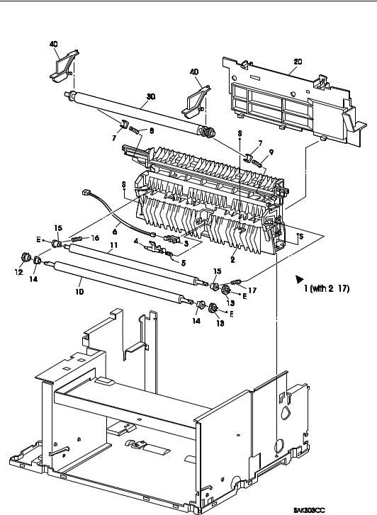
PL3 Paper Transportation
Parts Lists — LaserWriter 10/600 A3+ |
3 – 7 |
|||
|
|
PL3 Paper Transportation |
||
|
|
|
|
|
|
Item |
Parts Name |
High Assembly |
|
$ |
|
|
|
|
1 |
TRANSPORT CHUTE ASSEMBLY (with2-17) ............................ |
---- |
|
|
|
2 |
TRANSPORT SUB ASSEMBLY.................................................... |
PL3.1 |
|
|
3 |
REGISTRATION SENSOR............................................................. |
PL3.1 |
|
|
4 |
REGISTRATION ACTUATOR ...................................................... |
PL3.1 |
|
|
5 |
REGISTRATION SPRING .............................................................. |
PL3.1 |
|
|
6 |
REGISTRATION SENSOR HARNESS (P122-J123)..................... |
PL3.1 |
|
|
7 |
BTR BEARING................................................................................ |
PL3.1 |
|
|
8 |
BTR SPRING L................................................................................ |
PL3.1 |
|
|
9 |
BTR SPRING R................................................................................ |
PL3.1 |
|
|
10 |
RUBBER REGISTRATION ROLL................................................. |
PL3.1 |
|
|
11 |
METAL REGISTRATION ROLL ................................................... |
PL3.1 |
|
|
12 |
REGISTRATION IN GEAR ............................................................ |
PL3.1 |
|
|
13 |
REGISTRATION OUT GEAR ........................................................ |
PL3.1 |
|
|
14 |
REGISTRATION FRONT BEARING ............................................ |
PL3.1 |
|
|
15 |
REGISTRATION BACK BEARING .............................................. |
PL3.1 |
|
|
16 |
REGISTRATION ROLL SPRING L ............................................... |
PL3.1 |
|
|
17 |
REGISTRATION ROLL SPRING R............................................... |
PL3.1 |
|
|
20 |
CHUTE PLATE ............................................................................... |
---- |
|
$ |
30 |
BTR ASSEMBLY ........................................................................... |
---- |
|
|
40 |
BTR STOPPER *1 .......................................................................... |
---- |
|
*1 : This keeps the BTR ASSEMBLY attached with the Transport Sub Assembly during transportation. Remove it during installation.
Parts Lists — LaserWriter 10/600 A3+ |
3 – 8 |
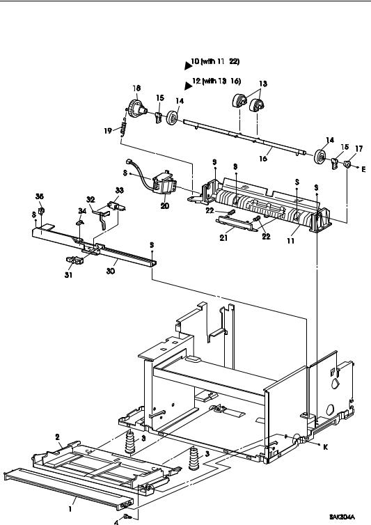
PL4 Multi Sheet Inserter
Parts Lists — LaserWriter 10/600 A3+ |
3 – 9 |
|||
|
|
|
PL4 Multi Sheet Inserter |
|
|
|
|
|
|
|
Item |
Parts Name |
High Assembly |
|
|
|
|
|
|
|
|
|
|
|
|
1 |
FRONT IN TRAY ............................................................................ |
---- |
|
|
2 |
FRONT BOTTOM TRAY ............................................................... |
---- |
|
|
3 |
MSI N/F SPRING............................................................................. |
---- |
|
|
4 |
BOTTOM TRAY STUD .................................................................. |
---- |
|
$ |
10 |
MSI CHUTE ASSEMBLY (with11-22) .......................................... |
---- |
|
|
11 |
MSI CHUTE..................................................................................... |
PL4.10 |
|
|
12 |
PICK UP ROLL ASSEMBLY (with13-16) ..................................... |
PL4.10 |
|
$ |
13 |
PICK UP ROLL *1........................................................................... |
PL4.12 |
|
|
14 |
CORE ROLL .................................................................................... |
PL4.12 |
|
|
15 |
PICK UP CAM ................................................................................. |
PL4.12 |
|
|
16 |
PICK UP SHAFT ............................................................................. |
PL4.12 |
|
|
17 |
TRANSPORT BEARING ................................................................ |
PL4.10 |
|
|
18 |
PICK UP GEAR ............................................................................... |
PL4.10 |
|
|
19 |
PICK UP SPRING............................................................................ |
PL4.10 |
|
|
20 |
PICK UP SOLENOID ...................................................................... |
PL4.10 |
|
$ |
21 |
RETARD PAD ASSEMBLY *1...................................................... |
PL4.10 |
|
|
22 |
RETARD SPRING ........................................................................... |
PL4.10 |
|
|
30 |
SENSOR BRACKET ....................................................................... |
---- |
|
$ |
31 |
MSI NO PAPER SENSOR............................................................... |
---- |
|
|
32 |
MSI N/P ACTUATOR ..................................................................... |
---- |
|
|
33 |
CLAMP S ......................................................................................... |
---- |
|
|
35 |
CLAMP M ........................................................................................ |
---- |
|
*1 : Periodic Replacement Parts
 Loading...