


 Loading...
K Service Source
LaserWriter 8500

K Service Source
Overview
LaserWriter 8500

Overview |
About This Overview - 1 |
|
|
|
|
About This
Overview
This overview briefly describes the servicing issues of the LaserWriter 8500, especially those that distinguish it from earlier Apple laser printers.
360 Degree View
LaserWriter 8500 Basic Configuration
Overview |
General - 2 |
|
|
|
|
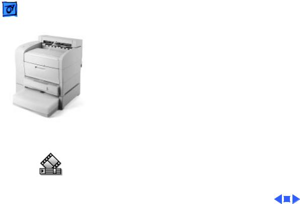
LaserWriter 8500 with Duplexer and Sheet Feeder
General
The LaserWriter 8500 is a 600 dpi, 20 ppm monochrome laser printer that is capable of printing onto paper up to 13 x 20 inches in size. In its basic configuration, the printer has a capacity of 650 sheets, the standard cassette holding 500 sheets (as compared to the 250 typical in earlier printers), the multipurpose tray holding 150.
There are several options available for the printer, including a duplexer unit (for two-sided printing), a 500sheet feeder, and an envelope cassette.
360 Degree View

Overview |
Duplexer - 3 |
|
|
|
|
Duplexer
Paper Path
Through Duplexer
Duplexer
The duplexer is an inverted L-shaped feeder that mounts onto the upper rear of the printer. Once installed, all paper (even simplex) diverts into and exits from the duplexer.
This is unlike the LaserWriter 12/640 PS, which employs a solenoid-actuated diverter controlled through software. The operative element in the LaserWriter 8500 is the exchange chute, located in the fuser assembly. The exchange chute is actuated (i.e. locked in place) during installation of the duplexer.
After the first pass of a duplex page, the paper partially exits the duplexer delivery rollers. The rollers then reverse and the paper feeds back down through the duplexer and into the printer engine, in preparation for imaging of the second side. The paper then exits through the duplexer into the delivery tray.

Overview |
Paper Path - 4 |
|
|
|
|
|
The duplexer derives its power from the printer engine but |
|
|
has its own motor to generate mechanical drive. |
|
Offset Function
The duplexer has a job separation feature that allows print jobs to be stacked offset (i.e. staggered left-to-right) in the delivery tray. Job separation is set in the Apple Printer Utility.
Note: Due to cost considerations, the offset function has been incorporated into the duplexer instead of the printer engine. Offsetting and duplex printing are otherwise unrelated to one another.
The offset motor in the duplexer generates the mechanical drive for offsetting paper.

Overview |
Sheet Feeder - 5 |
|
|
|
|
Sheet Feeder
As with the LaserWriter 16/600 PS and LaserWriter 12/ 640 PS designs, the sheet feeder fits squarely beneath the printer to form a dual front-loading cassette arrangement. Unlike those models, however, you can stack two feeders
Sheet Feeder beneath the printer, for a total auxiliary capacity of 1000 sheets. Also unlike those models, the sheet feeder and the engine use identical cassettes in the LaserWriter 8500.
The sheet feeder derives its power and mechanical drive from the printer engine.

Overview |
Form Factor - 6 |
|
|
|
|
 C
C 

D A
B
Printer Cross-Section Note: Diagram shows printer with long cassette and oversize (11 x 17 inch or A3) paper installed.
Form Factor
To achieve a reasonably compact form factor, the tail end of the cassette has been designed to extend out from the engine footprint (A). Consequently, the pickup rollers feed from the insertion end of the cassette (B), similar to the LaserWriter II. This arrangement influences the architecture of the printer in the following ways.
1Because pickup occurs deep within the printer, all mechanical drive elements are arranged vertically along the rear (C), resulting in a simple C-shaped paper path. This vertical arrangement yields a compact, lowmaintenance gear train, consisting at its essence of one gear assembly driven by one central motor.
2You can stack letter-sized paper on the multipurpose tray and shut the cover (D), thus hiding that paper from view inside a multipurpose “compartment.”

Overview |
|
|
Form Factor - 7 |
|
|
|
3 The design of the cassette bottom plate (A) is new. |
|
A |
|
Below the plate, three springs provide upward pressure |
|
|
|
|
C |
|
|
that forces the paper against the pickup rollers. (Only |
|
|
two of the springs are activated when the width guides |
|
|
|
|
|
B |
|
|
(B) are set for narrower paper). In most printers, the |
|
|
C |
bottom plate receives constant uniform pressure from |
|
|
the springs. As you insert the cassette, the paper snugly |
|
|
|
|
|
|
|
|
and passively presses against the pickup rollers. |
|
|
|
With this printer, however, the bottom plate must stay |
|
|
|
down during insertion to avoid snagging. The springs are |
|
|
|
released, and the bottom plate elevated against the pickup |
|
|
|
rollers, only when the cassette is fully inserted. |
|
|
|
This spring release is actuated by a latch on each side of |
|
|
|
the cassette near the leading edge (C). See “Cassette” in |
|
|
|
the Basics chapter for more information. |

 Overview Paper Orientation - 8
|
|
|
|
Feed |
|
Paper Orientation |
|
Long-Edge Feed |
|
|
|
|
|
|
The paper path is wide enough to print letter or A4 sized |
|
|
|
|
|
|
||
|
|
|
|
|
paper in long-edge feed (LEF) mode. LEF mode is recom- |
||
|
|
|
|
|
|
||
(LEF) |
|
|
|
|
|
||
|
|
|
|
mended as it achieves the fastest 20 ppm throughput and |
|||
|
|
|
|
|
|
|
|
|
|
|
|
|
|
|
|
|
|
|
|
|
|
|
optimizes duplex printing. |
|
|
|
|
Feed |
|
Note: The cassette automatically senses paper orientation. |
|
|
|
|
|
|
|
|
|
Short-Edge Feed |
|
|
|
|
|
|
The multipurpose tray does not. Printing in short-edge feed |
|
|
|
|
|
|||
|
|
|
|
|
(SEF) mode from the multipurpose tray may produce |
||
(SEF) |
|
|
|
|
|||
|
|
|
|
|
|
|
undesirable results. |
|
|
|
|
|
|
|
Paper orientation and how best to load paper can be |
|
|
|
|
|
|
|
confusing, especially when talking with customers over the |
|
|
|
|
|
|
|
phone. It is further complicated when printing duplex jobs. |
|
|
|
|
|
|
|
Keep in mind the following tips: |
|
|
|
|
|
|
|
• Use the LEF and SEF terms when talking about how paper |
|
|
|
|
|
|
|
is loaded. These are the terms found in the user manual. |
Overview |
|
Paper Orientation - 9 |
|
|
• The terms “portrait” |
|
|
and “landscape” are best |
|
|
used only when talking |
|
|
about how a printed page |
|
|
is to be formatted. |
|
|
Remember that LEF |
|
|
mode, for example, can |
|
|
result in either a |
|
|
landscape or a portrait |
|
|
formatted page. |
|
|
• Load letterhead face-up. |
|
|
• As you stand facing the |
|
|
printer: the top of the |
|
|
page is on the left for LEF |
|
|
portrait, and on the near |
|
LEF Paper Orientation |
side for LEF landscape. |
|
|

Overview |
Service Test Page - 10 |
|
|
|
|
Service Test Page
Service Test Page
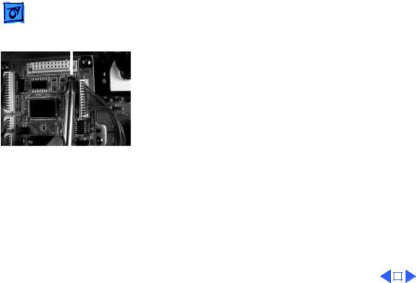
 Test Page Button
A service test page, sometimes called an engine test page, is a page whose description resides in firmware on the DC controller board. Successful printing of a service test page confirms the operation of the print engine. Of equal importance, if a print quality problem appearing on a normal page also appears on the service test page, the I/O controller board is proven good and should not be swapped.
There are two ways to print a service test page on the LaserWriter 8500.
1If the I/O board is installed, use a paper clip to press the test page button. This button is accessible through a small unmarked hole at the top of the I/O bracket.
Note: Use this button liberally, both in person and when troubleshooting with customers on the phone. It is your
Overview |
Service Test Page - 11 |
|||||
|
|
|
|
|
|
|
Test Page Jumper |
first line of defense in isolating faults between the I/O |
|||||
board and printer engine. |
||||||
|
|
|||||
|
|
2 If the I/O board and shield have been removed from the |
||||
|
|
printer, you can print a service test page by jumpering |
||||
|
|
the two pins of connector P23 on the DC controller |
||||
|
|
board. |
||||
|
|
|
|
|
|
|
|
|
|
|
|
|
|

Overview |
RAM Memory - 12 |
|
|
|
|
RAM Memory
The LaserWriter comes with 16 megabytes (MB) of RAM soldered onto the I/O controller board. There is one SIMM slot available for installing additional RAM. The following table lists the memory requirements and supported paper sizes for duplex printing and PhotoGrade.
Memory |
Duplex Printing |
PhotoGrade |
Use both features at once? |
|
16 MB |
Letter, A4, B4, legal |
Letter, A4, B5 |
No |
|
20 MB |
Letter, A3, A4, B4, |
Up to ledger and A3 |
Yes; up to letter and A4 |
|
|
legal, ledger |
|
|
|
24 MB |
Letter, A3, A4, B4, |
Up to Japan Standard |
Yes; up to legal |
|
|
legal, ledger |
and Japan Larger |
|
|
32 MB |
Letter, A3, A4, B4, |
All supported paper |
Yes; up to B4 |
|
|
legal, ledger |
sizes |
|
|
48 MB |
Letter, A3, A4, B4, |
All supported paper |
Yes; all supported paper |
|
|
legal, ledger |
sizes |
sizes |
|
|
|
|
|
|
|
|
|
|
|

 Overview SIMM Sizes and Speeds - 13
SIMM Sizes and Speeds
Size |
Configuration |
Speed |
Connector type |
||
4 MB SIMM |
1 |
M X 32 bit (one 4 MB bank) |
70 ns or less |
72-pin |
|
8 MB SIMM |
2 |
M X 32 bit (two 4 MB banks) |
70 ns or less |
72-pin |
|
16 |
MB SIMM* |
4 |
M X 32 bit (one 16 MB bank) |
70 ns or less |
72-pin |
32 |
MB SIMM* |
8 |
M X 32 bit (two 16 MB banks) |
70 ns or less |
72-pin |
*Must have a 2 KB row (11 bit x 11 bit) refresh rate. 16 MB SIMMs with a 4 KB row (12 bit x 10 bit) refresh rate are not compatible with the printer.
Overview |
Miscellaneous - 14 |
|
|
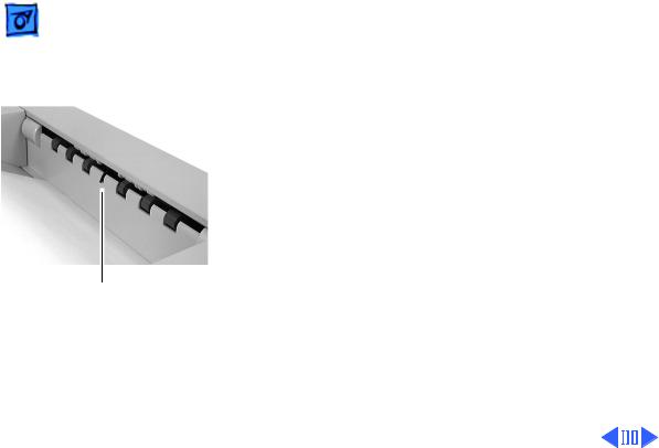
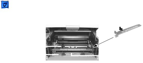
Actuator for Full-Stack Sensor
Miscellaneous
Full-Stack Sensor
When the delivery tray is full of paper, the printer stops accepting print jobs and the controller reports an error message to the host computer. Sensing of delivery tray capacity is done through the full-stack sensor located just above the delivery rollers.
With a duplexer installed, the duplexer full-stack sensor assumes this function. The parts used in the duplexer actuator and the printer actuator are not interchangeable.
Other Sensors and Interlocks
All other sensors and interlocks are similar to previous printers and will be familiar to the experienced technician. See “Sensing System Locator” in the Basics chapter for a

Overview |
Miscellaneous - 15 |
|
|
|
|
|
comprehensive diagram. |
|
|
There is also a mechanical interlock that disengages the |
|
|
fuser assembly drive train when the top cover is open (to |
|
|
facilitate removal of paper jams). See “Top Housing and |
|
|
Xerographics” in the Basics chapter. |
|
|
Point-of-Sale (POS) Button |
|
|
The Ready LED is also a button that actuates a microswitch on |
|
|
the status panel board. If you hold this LED during printer |
|
|
startup, the printer will enter the special POS state (or exit |
|
|
from POS if POS is currently enabled). You can also make |
|
|
these settings through the Printer Utility. |
|
|
During POS state, the ready LED flashes two shades of green |
|
Demonstration Page |
instead of the normal steady green. When you press the |
|
ready LED thereafter, a special demonstration page will |
||
|
||
|
print. While in POS state, the energy saving feature is |

Overview |
Miscellaneous - 16 |
|
|
|
|
|
disabled, but in all other ways, the printer is network- |
|
|
aware and will perform just as it does in ready state. |
|
Voltage-Specific Parts
Four parts in the printer are available in both 110V and 220V versions:
• Power supply
• Fuser assembly
• Transport chute assembly
• DC controller board
Note: The DC controller board, though universal in previous printers, is not in the LaserWriter 8500.
The second version of this board satisfies European Economic Community requirements and has made possible some localization of controller board firmware (default paper size for the multipurpose tray, for example).
 Overview Miscellaneous - 17
|
|
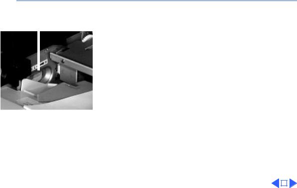
Density Adjustment |
||
Density Adjustment Dial |
On the left side of the multipurpose tray compartment, there |
|||
|
|
|||
|
|
|||
|
|
is a density adjustment dial. This dial changes the DC |
||
|
|
component of the development bias voltage supplied by the |
||
|
|
high-voltage power supply. The dial adjusts the threshold |
||
|
|
voltage, in effect changing the background density across the |
||
|
|
entire imageable page. |
||
|
|
A second method of density adjustment is through the Apple |
||
|
|
Printer Utility, which adjusts the laser power output. In |
||
|
|
effect, this adjusts the density of the printed pixels. |
||
|
|
|
|
|
|
|
|
|
|

K Service Source
Basics
LaserWriter 8500
Basics |
Function of Main Components - 1 |
|
|
|
|
Function of Main Components
This topic describes the function of the following components of the LaserWriter 8500. •Cassette
•Cassette Feed Components
•Manual Feed Components
•Paper Transportation
•Fusing and Paper Exit
•Frame and Drive
•Top Cover and Xerographics •Electrical
Cassette
Paper Width Guides
The paper width guides are adjusted left-to-right to accommodate different paper widths. They contact the left and right sides of the paper stack and hold the paper stack in place in the crosswise direction.
The left and right snubbers (paper separating claws) at the leading edge of paper allow only one sheet of paper to be fed from the cassette into the printer. The snubbers move together with the paper width guides.
Pressure Plate Springs
Two pressure springs act against the bottom plate when paper width is less than 8.5 inches (216 mm). When the paper width is greater, additional forced is deemed necessary and a third pressure spring is released against the bottom plate. The mechanism that releases or contains the third spring is controlled by the paper width guides.
Bottom Plate Assembly
Left Width Guide |
Pressure Plate Springs |
|
Size Cams
Right Width Guide
Paper End Guide

Basics |
Function of Main Components - 2 |
|
|
|
|
Paper End Guide
The paper end guide can be adjusted front-to-rear to accommodate different paper lengths. It is in contact with the trailing edge of the paper stack.
When the paper end guide is adjusted, the size cams on the left side of the cassette rotate into a unique pattern of projections and gaps. When you insert the cassette, the position of the cams align with actuators that are housed in the printer’s left cassette guide assembly. The actuators correspond to four microswitches on the cassette feed board.
Cassette |
Size |
Size |
|
||
|
Cam |
Cam |
|
Size Actuator |
Size Actuator |
|
Size Switch |
Size Switch |
Cassette Feed Board |
|
Cassette Feed Board |
Cassette Latches
On each side near the leading edge of the cassette are two cassette latches. When the cassette is outside the printer, these latches hold the bottom plate down against the force of the pressure plate springs. As the cassette is inserted, the latches release and the bottom plate elevates.
Bottom Plate Assembly
|
Right Cassette |
|
Latch |
Cassette |
Bottom Plate Assembly |
Cassette Guide
(in Printer)

Basics |
Function of Main Components - 3 |
|
|
|
|
Cassette Feed Components
Turn Clutch |
|
|
|
|
|
|
|
Cassette Feeder Board |
|
|
|||||||
Cassette Feed Solenoid |
|
|
|
|
|
|||
|
||||||||
|
|
|
|
|||||
and Feed Gear |
|
|
Cassette Paper-Present |
|||||
|
|
|
|
|
|
|
|
|
|
|
|
|
|
|
|
|
|
|
|
|
|
|
|
|
|
Sensor and Actuator |
Cassette Feeder Board
The feeder board has the paper size microswitches (see previous topic) and serves as a relay board for the signals between the cassette feed and the DC controller board.
Cassette Paper-Present Sensor and Actuator
This sensor detects the presence of paper in the cassette.
Cassette Feed Solenoid and Feed Gear
When the feed solenoid is actuated, the feed gear is releases and turns to engage with the feed idler gear. The feed gear then begins to rotate, causing the pickup rollers to rotate. After one revolution, the feed gear disengages from the feed idler gear and is latched by the pawl of the feed solenoid.
Turn Clutch
The turn clutch is an electromagnetic clutch that switches on and off the drive power to the lower and upper feed rollers.
Lower and Upper Feed Rollers
These rollers have an integral metal shaft/rubber roller design. Drive to the rollers is controlled by the turn clutch so that the rollers start feeding from the pickup area and stop feeding at the registration sensor.
When the engine receives a /PRFD signal from the controller, the engine stops feeding at the registration sensor and resumes when it receives a subsequent /START signal. If the / START signal is received before the paper reaches the registration position, the printer will feed the paper continuously without stopping the rotation of the feed rollers.
Pickup Rollers
Rotate and feeds one sheet of paper each time the cassette feed solenoid is actuated.
Basics |
Function of Main Components - 4 |
|
|
|
|
Manual Feed Components
|
|
|
|
|
Manual Feed |
|
|
|
|
|
Sensor Assembly |
Toner Sensor |
|
|
|
|
|
|
|
|
|
|
|
Manual Feed Guide Tray |
|
|
|
|
Manual Feed |
|
|
|
|
||
|
|||||
|
|
|
|
||
|
|
|
|
|
Paper-Present Sensor |
Manual Feed Guide Tray
The manual feed guide tray is the pressure plate and width guide for manual feed paper. During standby the tray is held down by the pickup roller assembly cams. When the paper is about to feed, the cams move off the tray due to the rotation of the pickup roller assembly. The manual feed guide tray is therefore pressed up by the two pressure springs and the paper is pressed against the pickup roller.
Manual Feed Paper-Present Sensor
Part of the manual feed sensor assembly, this sensor detects the presence of paper in the manual feed compartment.
Toner Sensor
Also part of the manual feed sensor assembly, this sensor detects low toner by responding to the magnetism of the toner in the cartridge.

Basics |
Function of Main Components - 5 |
|
|
|
|
Paper Transportation
Transfer Roller Assembly |
|
Transport Chute Assembly |
|
||
|
|
Transfer Roller Assembly
The transfer roller is in contact with the drum in the toner cartridge. The roller is driven by the drum gear so that the roller surface moves at the same speed as the drum surface.
The transfer roller applies a positive charge to the back side of the paper when the paper travels between the roller and the drum. The negatively charged toner image transfers from the drum surface to the front side of the paper because it is attracted by the positive charge on the back side of the paper.
Transport Chute Assembly
Transport Chute Assembly
|
Photosensitive Drum |
Detack Saw |
|
Transfer Roller |
Toner |
Cartridge |
|
Registration Actuator |
|
Registration Sensor |
|
Rear Chute Assembly |
|
Rubber Registration Roller |
Pickup Roller |
Metal Registration Roller |
Separation Pad |
Included in the transport chute assembly are the following components.
Pickup roller assembly: Consists of two pickup rollers, three core rollers, pickup cams, and the shaft. It rotates one turn each time the manual feed pickup solenoid is actuated, and feeds one sheet of paper from the manual feed compartment.
Pickup solenoid and pickup gear: When the pickup solenoid is actuated, the pickup gear is released and turned by the pulling force of the pickup spring to engage with the opposite gear in the main gear assembly. The pickup gear then begins to rotate, causing the pickup roller assembly to rotate. After one revolution, the pickup gear disengages from the opposite gear because of its sector-shaped cutout and is latched by the pawl of the feed

Basics |
Function of Main Components - 6 |
|
|
|
|
solenoid.
Separation pad assembly: Prevents extra sheets of paper from being fed by the friction between the paper and the rubber of the separation pad.
Rear chute assembly: Guides the paper fed from the cassette between the metal and rubber registration rollers.
Metal registration roller and rubber registration roller: The rotation of these rollers is controlled by means of the registration clutch assembly so as to register the paper with the image on the drum.
Registration sensor: Detects the arrival and departure of the paper at the registration position.
Transfer roller bearing: Applies the transfer voltage from the high-voltage power supply to the transfer roller assembly.
Detack saw: Imparts a negative charge to the back side of the paper, partially neutralizing the positive charges, so that the paper can peel off the drum.
Duplexer
The duplexer derives its mechanical drive from the duplex motor. The offset motor generates the lateral drive for job separation (left-to-right staggering of paper in the delivery tray).
|
Gear B |
Duplex Motor |
|
|
Duplexer |
|
|
Gear B |
|
|
Gear C |
Offset Gear |
Gear A |
Gear D |
|
|
|
|
|
Pulley Gear |
|
Drive Belt |
|

 Pulley Gear
 Basics Function of Main Components - 7
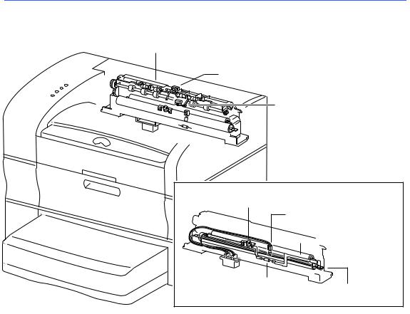
Fusing and Paper Exit
Fuser Assembly
 Full Stack Sensor and Actuator
Exit Sensor and Actuator
Thermostat
Temperature Sensor
Assembly
 Pressure Roller
Thermal Fuse |
Fuser Bulb |
|
|
|
(Inside Heat Roller) |
The fuser assembly houses all components of fusing (the permanent fixing of toner to paper by means of heat and pressure), as well as components for paper delivery.
Heat Roller
The heat roller is a hollow metal tube that applies heat to the paper passing between it and the pressure roller. The heat is generated by the fuser bulb inside the heat roller. This heat melts the toner on the paper.
Pressure Roller
The pressure roller is a solid, sponge rubber-coated metal shaft that presses the paper against the heat roller. The pressure helps bond the toner to the paper.
Heater Assembly
The heater assembly consists of the fuser bulb and the wiring and connectors attached to the ends of the bulb.
Temperature Sensor Assembly
The temperature sensor assembly is a thermistor whose resistance varies sharply with a change in temperature. This sensor is held in contact with the heat roller surface and monitors the temperature thereof. The signal from this sensor is used to maintain the temperature of the heat roller surface within the specified range by switching the power to the heater bulb on and off. The signal is also used for the first-stage overheat protection.
Thermostat
The thermostat is part of the heater bulb circuit ad functions as the second-stage overheat

Basics Function of Main Components - 8
protection. If the temperature sensor assembly fails to prevent a fuser overheat, the thermostat opens and power is cut to the heater bulb.
Thermal Fuse
Also a part of the heater bulb circuit, the thermal fuse functions as the third-stage overheat protection. If both the first and second stages fail to prevent a fuser overheat, the thermal fuse opens and power is cut to the heater bulb.
Heat Roller Diode
There is a negative charge that builds up on the heater bulb. This charge can disturb the toner image on the paper during fusing. The heat roller diode grounds this charge.
Full Stack Sensor
|
Full Stack Actuator |
|
Exit Sensor |
|
To Duplexer |
|
|
|
|
Exit |
Exchange |
|
Chute |
|
|
Roller |
Chute |
Exit Actuator |
|
|
Heat Roller Finger |
|
|
|
Fuser Assembly |
|
Heat Roller |
|
|
Pressure Roller |
|
|
Heat Roller Fingers
These fingers work in conjunction the non-stick coating of the heat roller to peel the leading edge of the paper from the roller.
Exit Sensor
The exit sensor detects the arrival and departure of the paper on the delivery side of the heat roller.
Full Stack Sensor
The full stack sensor detects when the delivery tray is full of paper.
Exchange Chute
The installation of an optional duplexer locks the exchange chute into a position so that all paper is directed up into the duplexer.
Basics |
Function of Main Components - 9 |
|
|
|
|
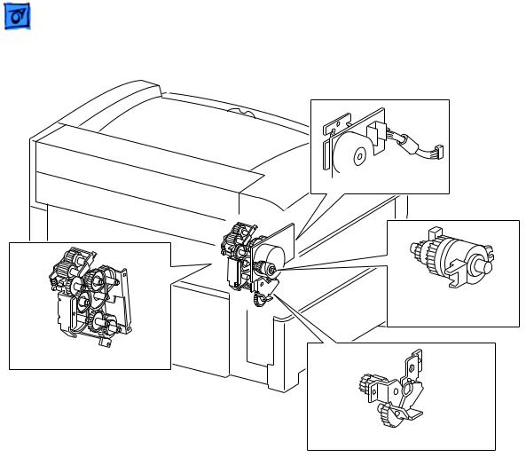
Frame and Drive

 Main Motor
Registration Clutch
Assembly
Main Gear Assembly
Paper-Handling Gear Assembly
Main Motor
Generates all the drive power for the printer and optional sheet feeder.
Main Gear Assembly
Distributes drive power from the main motor to the fuser assembly, toner cartridge, paper handling gear assembly, registration clutch assembly, and pickup gear.
Paper Handling Gear Assembly
Transfers the drive power from the main gear assembly to the feed idler gear and to a second gear within the main gear assembly.
Registration Clutch Assembly
An electromagnetic clutch that switches the drive power on and off to the two registration rollers at a specified time after the registration sensor has detected the arrival of the paper. This clutch actuates momentarily after the paper arrives at the registration rollers to allow the feed rollers to remove any skew induced during paper feed.
Basics |
Function of Main Components - 10 |
|
|
|
|
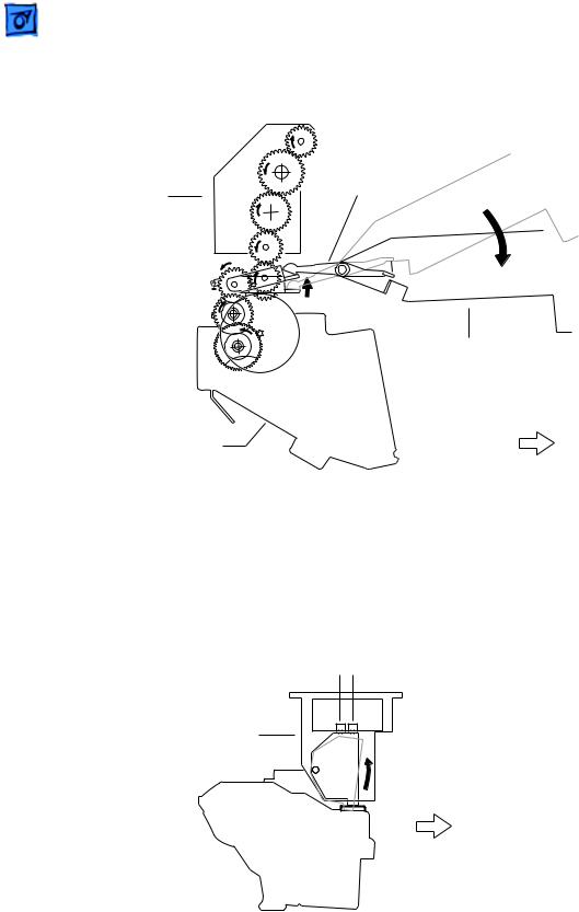
Top Housing and Xerographics
Guide Arm and Fuser Guide Lever
|
Fuser Guide |
Fuser Assembly |
Lever |
|
Top Cover
Main Gear Assembly |
Front |
When the top cover opens, the fuser guide lever presses down on the floating idler gear at the top of the main gear assembly, thus disengaging the fuser assembly from the gear train. This makes removal of paper jams from the fuser much easier. When the top cover is closed, the floating idler gear springs upward to mate the fuser gearing to the main gear train.
Cartridge Sensor Assembly
Cartridge-Present Switch |
|
|
|
LD Switch |
|
|
Cartridge Sensor Assembly
Toner |
Front |
|
|
Cartridge |
|
The cartridge sensor assembly houses the two switches below.
Cartridge-present switch: The signal from this switch stops printer operation when the toner cartridge is absent or the top cover is open.
Loading...