


 Loading...
K Service Source
LaserWriter Pro 600/630
LaserWriter Pro 600, LaserWriter Pro 630

K Service Source
Basics
LaserWriter Pro 600/630

Basics |
Product Information - 1 |
|
|
Product Information
The printers covered in this manual are the LaserWriter Pro 600 and LaserWriter Pro 630. Except for the I/O boards, all parts are identical between the two models.

Basics |
Product Information - 2 |
||
|
|
||
|
Note: Refer to the following chapters in the Envelope Feeder |
||
|
LW Pro-LW 16/6 and Sheet Feeder LW Pro-LW 16/6 |
||
|
manuals for additional information on feeder options. |
||
|
– Take-Apart |
||
|
– Additional Procedures |
||
|
– Adjustments |
||
|
– Illustrated Parts |
||
|
|
|
|
|
|
|
|

 Basics LaserWriter Utility - 3
LaserWriter Utility
Note: Refer to the user's guide for complete information regarding LaserWriter Utility. This application gives you software control over the LaserWriter Pro that is essential to its operation. Some of features of LaserWriter Utility include:
– Naming the printer
– Setting default printer resolution
– Turning on FinePrint
– Turning on PhotoGrade (if available)
– Setting default paper-handling options
– Setting print density
– Setting communication protocols
– Printing configuration page
– Turning off the startup test page
Note: You must use LaserWriter Utility version 7.4 or

Basics |
LaserWriter Utility - 4 |
||
|
|
||
|
later. You can override some default settings through the |
||
|
Print dialog (LaserWriter driver version 7.2 or later). |
||
|
|
|
|
|
|
|
|
Basics |
Paper Path - 5 |
|
|
Optional
* Envelope
Feeder (75)
Multipurpose
Tray (100)
Standard
Cassette (250)
Optional Sheet
Feeder (500)
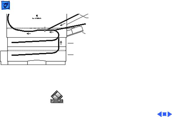
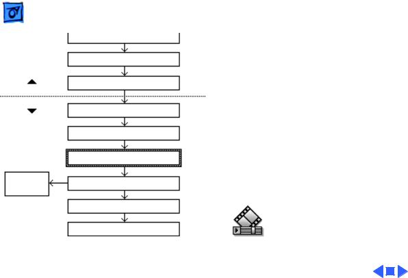
Paper Path
There are four paper sources and one output tray in a complete system. The number in parenthesis is the capacity of the paper source.
Note: The asterisk at the point where the paper paths meet denotes a synchronization pause. See PS602 in “Sensing System Theory” in this chapter.
Basics |
Mechanical Drive Theory - 6 |
|
|
M1
M2
M3
|
Mechanical Drive |
|
M4 |
Theory |
|
|
|
|
|
There are four motors and |
|
|
four separate drive trains in |
|
|
a complete system. Two are |
|
|
in the printer engine and one |
|
|
is in each of the optional |
|
|
feeders. |
|
|
• M1 |
Main Motor |
|
• M2 |
Pickup Block Motor |
|
• M3 |
Sheet Feeder Motor |
|
• M4 |
Envelope Feeder |
|
Motor |
|
Basics |
Mechanical Drive Theory - 7 |
|
|
Power |
DC Controller Board |
A |
||
Supply |
|
|||
|
|
|
|
|
|
Connecting Cable |
|
||
|
|
Main Motor |
B |
|
|
|
|
||
|
Drive Assembly |
C |
||
|
|
|||
Toner Cartridge |
D |
Fuser Assembly |
||
|
||||
|
|
|
Gears/Rollers |
|
Transfer Roller |
E Delivery Roller Assy |
|||
|
|
|
Gears/Belt/Rollers |
|
F G
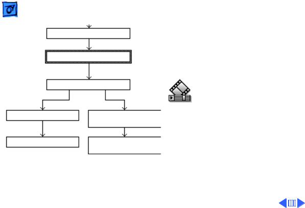
M1 Main Motor Drive
The main motor powers the system that transports paper from the toner cartridge to the delivery tray on top of the printer.
Note: The letters next to the boxes correspond to the labels in the mechanical drive animations that are available on the CD.
Basics |
Mechanical Drive Theory - 8 |
|
|
Power |
DC Controller Board |
A |
Supply |
|
|
|
|
|
|
Connecting Cable |
|
|
Pickup Controller Board |
H |
|
|
|
|
Pickup Sensor Board |
J |
|
|
|
|
Pickup Block Motor |
K |
|
|
|
Pickup |
|
|
Solenoids |
|
|
|
Gear/Roller System |
|
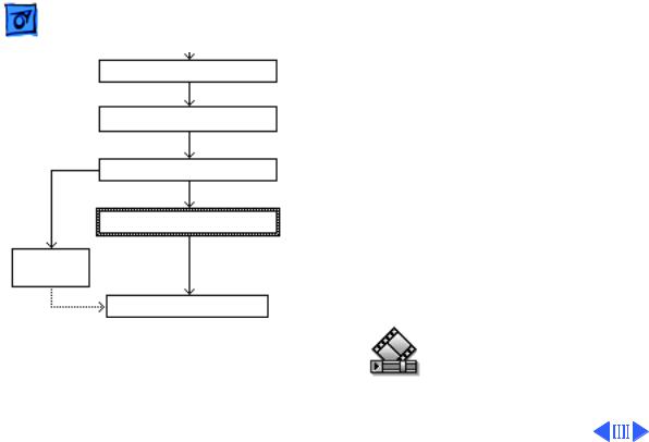
M2 Pickup Block Motor Drive
The pickup block motor powers the system that transports paper into the engine, through the pickup block, and up to the toner cartridge.
Note: The DC controller board does not connect directly to the pickup block motor. Make sure to troubleshoot the three intermediate blocks if there is a failure in pickup block drive.
Basics |
Mechanical Drive Theory - 9 |
|
|
Power
Supply
ENGINE
SHEET FEEDER
Pickup
Solenoid
DC Controller Board |
A |
|
|
Connecting Cable |
|
Pickup Controller Board |
H |
|
|
Connecting Cable |
|
Controller Block |
L |
|
|
Feeder Controller Board |
M |
|
|
Sheet Feeder Motor |
N |
|
|
Gear/Roller System |
|
M3 Sheet Feeder Motor Drive
The sheet feeder motor powers the system that transports paper from the 500-sheet cassette upward into the printer engine.
Note: Once the paper reaches the lower feed roller in the pickup block, engine components supply mechanical drive.
Basics |
Mechanical Drive Theory - 10 |
|
|
Power
Supply
ENGINE
ENV FEEDER
Pickup
Rollers
DC Controller Board |
A |
|
|
Connecting Cable |
|
Pickup Controller Board |
H |
|
|
Connecting Cable |
O |
|
|
Connecting Cable |
|
Feeder Controller Board |
P |
|
|
Envelope Feeder Motor |
Q |
|
|
Drive Assembly |
|
Primary Feed Roller |
|
Separation Drive Assy |
|
M4 Envelope Feeder Motor Drive
The envelope feeder motor powers the system that separates envelopes and feeds them into the printer engine.
Note: Once an envelope reaches the upper feed rollers in the pickup block, engine components supply mechanical drive.

Basics |
Sensing System Theory - 11 |
|
|
Sensing System Theory
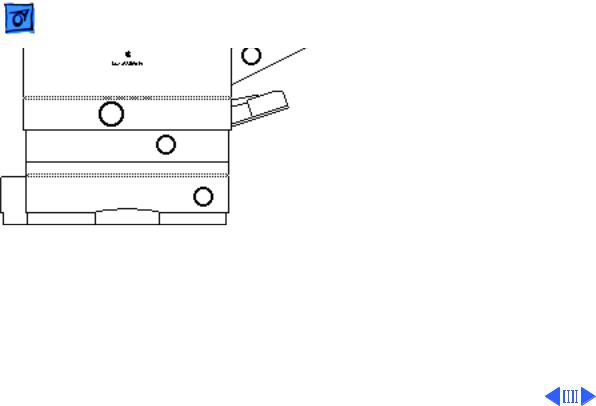
There are six paper sensors, one dual-purpose sensor, and seven sensing switches in a LaserWriter Pro 600/630 PS system:
Paper Sensors
– PS601: Cassette Paper Sensor
– PS602: Registration Paper Sensor
– PS701: Multipurpose Paper-End Sensor
– PS702: Multipurpose Paper-Present Sensor
– PS851: Sheet Feeder Paper-Present Sensor
– PS931: Envelope Paper-Present Sensor
– PS201: Delivery/Interlock Sensor
Sensing Switches
– SW601: Top Cover Interlock Switch
– SW603: Upper Cassette Size Sensing Switch

Basics |
Sensing System Theory - 12 |
|
|
|
– •SW604: Upper Cassette Size Sensing Switch |
|
– •SW605: Upper Cassette Size Sensing Switch |
|
– •SW851: Lower Cassette Size Sensing Switch |
|
– •SW852: Lower Cassette Size Sensing Switch |
|
– •SW853: Lower Cassette Size Sensing Switch |
Basics |
Sensing System Theory - 13 |
|
|
Actuator |
Paper Sensors |
|
|
|
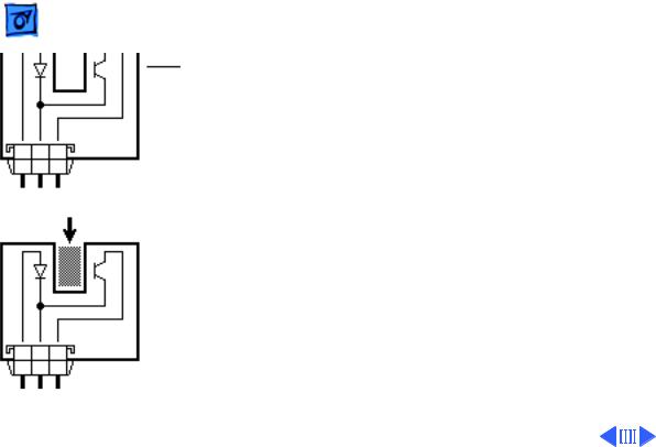
Paper sensors consist of an |
Photointerrupter |
actuator, a U-shaped photo |
|
interrupter, and circuitry. |
|
Sensors are tripped as the |
|
actuator swings against |
OPEN |
movement of paper and |
|
blocks the gap of the U. An |
|
actuator can be passive |
|
(governed by gravity) or |
|
spring-loaded. |
|
Note: Sensor failure can be |
|
either mechanical or |
|
electrical. When |
|
troubleshooting sensors, |
CLOSED |
first confirm that the arm |
|

Basics |
Sensing System Theory - 14 |
|
|
|
or lever moves freely without snagging, that any springs are |
|
applying correct resistance, and that the actuator is not |
|
broken. Then check that all cable connections are secure. If |
|
you have eliminated mechanical issues, proceed with |
|
electrical troubleshooting. |

Basics |
Sensing System Theory - 15 |
|
|
Sensor
Holder
Assembly
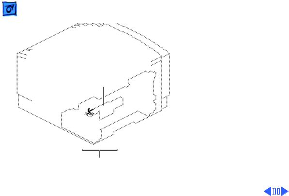
PS601
Paper
Pickup Block
PS601
Cassette Paper Sensor
Actuator: A passive lever in the sensor holder assembly is tripped by insertion of a loaded cassette tray.
Basics |
Sensing System Theory - 16 |
|
|
Sensor
Holder
Assembly
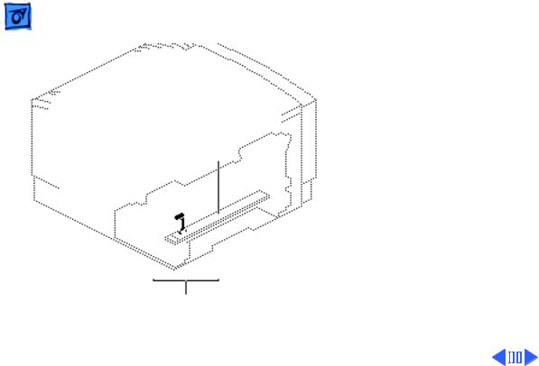
PS602
Paper
Pickup Block
PS602
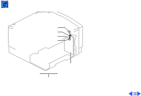
Registration Paper Sensor
Actuator: A spring-loaded lever in the sensor holder assembly is tripped by arriving paper.
All paper stops at PS602 and waits for proper synchronization with drum rotation and mechanical drive.
Note: If paper does not reach sensor PS602 within the prescribed time after the pickup signal is issued, a

Basics |
Sensing System Theory - 17 |
|
|
|
pickup unit delay jam exists and the controller stops |
|
printing. |
|
If paper reaches the sensor but does not clear it within the |
|
correct time, a pickup unit stationary jam exists. The time |
|
allowed for paper to clear is a function of paper size, which |
|
is detected by PS701 (for manually fed paper) and by |
|
sensing switches (for cassette-fed paper). |
Basics |
Sensing System Theory - 18 |
|
|
Pickup
Sensor
Board
PS702
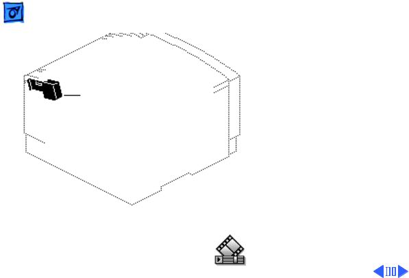
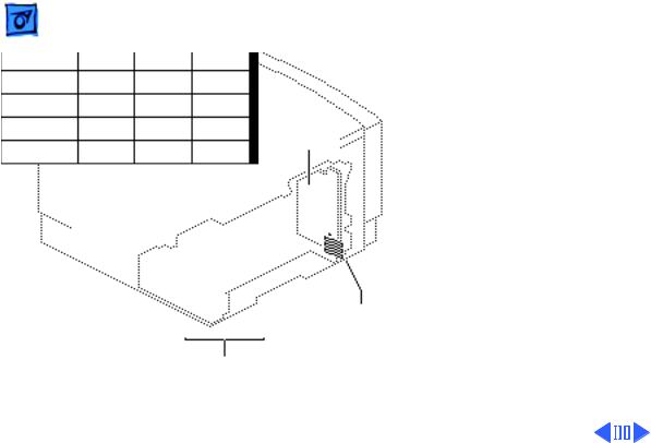
Multipurpose PaperPresent Sensor
Actuator: A spring-loaded lever in the paper pickup block is tripped by the leading edge of paper as it is loaded in the multipurpose tray.
PS702
Paper
Pickup Block
Basics |
Sensing System Theory - 19 |
|
|
Pickup
Sensor
Board
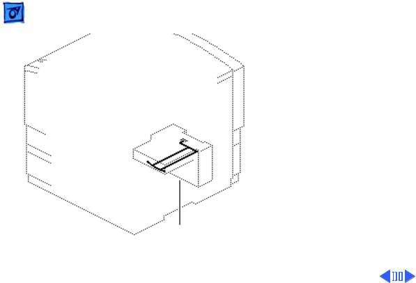
PS701
PS701
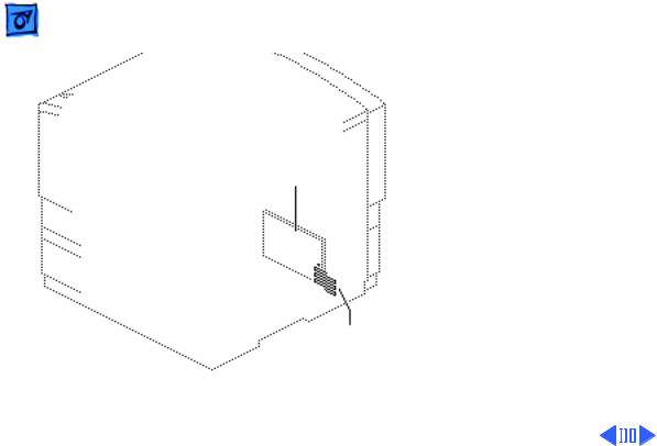
Multipurpose Paper-End Sensor
Actuator: A passive lever in the paper pickup block is tripped by the trailing edge of paper leaving the multipurpose tray.
Sensor PS701 detects the size of paper fed from the multipurpose tray.
Paper
Pickup Block
Basics |
Sensing System Theory - 20 |
|
|
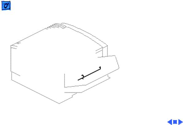
PS201
Delivery/Interlock Sensor
Actuator: A plastic tab on the fuser door and a sensing lever in the fuser assembly
Delivery/Interlock Sensor act independently to trip a photo interrupter.
PS201 detects two things: paper exiting the fuser and closure of the fuser door.
Note: If paper does not reach sensor PS201 within 5.2 seconds after it reached registration sensor J602, a delivery unit delay jam

Basics |
Sensing System Theory - 21 |
|
|
|
exists and the controller stops printing. |
|
If paper reaches the sensor but does not clear it within the |
|
correct time, a delivery unit stationary jam exists. The |
|
time allowed for paper to clear is a function of paper size, |
|
which is detected by PS701 (for manually fed paper) and by |
|
sensing switches (for cassette-fed paper). |
Basics |
Sensing System Theory - 22 |
|
|
PS851
Sheet Feeder PaperPresent Sensor
Actuator: A passive lever in the controller block is tripped by insertion of a loaded cassette tray.
PS851
Controller
Block
Basics |
Sensing System Theory - 23 |
|
|
PS931
Envelope Feeder PaperPresent Sensor
Actuator: A spring-loaded lever is tripped by placement of envelopes into the feeder.
 Basics Sensing System Theory - 24
Circuit Board |
Sensing Switches |
||
|
|||
|
|
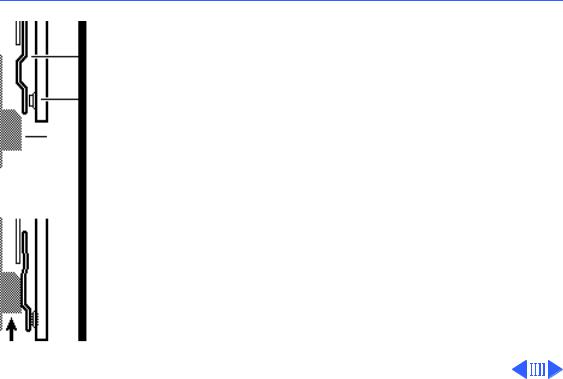
Sensing switches attach to a |
|
Leaf Spring |
circuit board and do not use |
||
|
|
photo interrupters. |
|
Microswitch |
Switches are actuated by leaf |
||
|
|
||
Actuator |
|
springs that press inward as |
|
Microswitch ON |
you insert a cassette tray or |
||
|
|||
|
close the top cover. |
||
|
|
||
|
|
Failure in sensing switches |
|
|
|
can be either mechanical or |
|
|
|
electrical. When |
|
|
|
troubleshooting switches, |
|
|
|
first confirm that the |
|
|
|
actuator has not broken off |
|
|
Microswitch OFF |
and then confirm that the |
|
|
|
leaf springs are not bent or |
|

Basics |
Sensing System Theory - 25 |
|
|
|
misshapen. You should be able to press the leaf spring with |
|
your finger and hear the clicking of the microswitch. |
|
If you have eliminated mechanical issues, proceed with |
|
electrical troubleshooting. |
Basics |
Sensing System Theory - 26 |
|
|
Cover Interlock Arm
Cover Interlock Spring
Cover Interlock Actuator
SW601
Pickup
Controller
Board
Paper
Pickup Block
SW601
Top Cover Interlock Switch
Actuator: A tab on the top cover actuates a leaf spring and pin, which press the microswitch on the pickup controller board. See “Troubleshooting Tips” in Troubleshooting for information on defeating the top cover interlock switch.
Basics |
Sensing System Theory - 27 |
|
|
|
|
|
|
Cassette |
SW603 |
SW604 |
SW605 |
(None) |
OFF |
OFF |
OFF |
Legal |
ON |
ON |
OFF |
Letter |
ON |
OFF |
ON |
A4 |
OFF |
OFF |
ON |
Executive |
OFF |
ON |
ON |
B5 |
OFF |
ON |
OFF |
|
|
|
|
Paper
Pickup Block
Pickup
Controller
Board
SW603
SW604
SW605
SW603/4/5
Cassette Size Sensing Switches (Upper)
Actuator: Plastic tabs on the side of the cassette trays actuate leaf springs, which press microswitches on the pickup controller board. The tab/switch configurations are as shown.
Note: See the next page for a note regarding the 250sheet universal cassette.
Basics |
Sensing System Theory - 28 |
|
|
Sheet Feeder
Controller Board
SW851
SW852
SW853
SW851/2/3
Cassette Size Sensing Switches (Lower)
Actuator: Plastic tabs on the side of a cassette tray actuate leaf springs, which press microswitches on the sheet feeder controller board.
Note: The sheet feeder uses a 500-sheet universal cassette. As with the upper 250-sheet universal cassette, the tabs are set manually by adjusting a selection dial on the cassette.
Loading...