


 Loading...
Apple Technician Guide
Mac Pro (Early 2009)
Updated: 2010-06-03

Apple Inc.
© 2009 Apple Inc. All rights reserved.
Under the copyright laws, this document may not be copied, in whole or in part, without the written consent of Apple.
Every effort has been made to ensure that the information in this document is accurate. Apple is not responsible for printing or clerical errors.
Apple
1 Infinite Loop Cupertino, CA 95014-2084 USA
+ 1 408 996 1010 www.apple.com
Apple, the Apple logo, Mac, and Macintosh are trademarks of Apple Inc., registered in the U.S. and other countries.

Mac Pro (Early 2009)
Contents
About This Guide
Manual Updates 8
Feedback 9
Basics
Overview 11
How to Identify Quad-Core and 8-Core Processor Configurations 12
Serial Number Location 13
Troubleshooting
General Troubleshooting |
15 |
||
Update System Software |
15 |
||
Troubleshooting Theory |
15 |
||
Emerging Issues 15 |
|
|
|
Hardware vs. Software |
15 |
|
|
Mac Pro Firmware Updates 16 |
|||
Memory Configuration |
17 |
||
Memory Diagnostic LEDs |
19 |
||
PCIe/Graphics Cards |
21 |
|
|
Functional Overview |
22 |
|
|
Block Diagram 24 |
|
|
|
Common Reset Procedures 25 |
|||
Power-On Self Test:RAM and Processor Verification 27 |
|||
Minimum Configuration Testing 28 |
|||
Processor Diagnostic LEDs |
32 |
||
Symptom Charts Overview 34
Startup and Power Issues 37
No Power/Dead Unit 37
Intermittent Shutdown 40
Memory Issues/Kernel Panic and Freezes 43
No Video 48
Power, but No Boot 51

Noise/Hum/Vibration 52
Burnt Smell/Odor 54
Uncategorized Symptom 55
Communications |
56 |
|
|
|
|
|
Ethernet Port/Device Issue 56 |
|
|
|
|
||
AirPort/Bluetooth:Defective Wireless Devices |
58 |
|||||
No/Poor Wireless Signal 60 |
|
|
|
|
||
Wireless Input Device Loses Connection 62 |
|
|||||
AirPort Card:Kernel Panic 64 |
|
|
|
|
||
Wireless Performance Issue / Slow Connection |
65 |
|||||
Wireless Input Device Doesn’t Pair 67 |
|
|
|
|||
Uncategorized Symptom 69 |
|
|
|
|
||
Mass Storage 70 |
|
|
|
|
|
|
Hard Drive Read/Write Issue 70 |
|
|
|
|
||
Hard Drive Not Recognized/Not Mounting |
72 |
|||||
Hard Drive Noisy |
74 |
|
|
|
|
|
Optical Drive Won’t Accept/Reject Media |
75 |
|
||||
Optical Drive Read/Write Data Error 77 |
|
|
||||
Optical Drive Not Recognized/Not Mounting |
79 |
|||||
Optical Drive Noisy |
81 |
|
|
|
|
|
Optical Drive Not Performing to Specs |
84 |
|
|
|||
Uncategorized Symptom 85 |
|
|
|
|
||
Input/Output Devices |
86 |
|
|
|
|
|
USB Port Does Not Recognize Known Devices |
86 |
|||||
FireWire Port Does Not Recognize Known Good Devices 87 |
||||||
No Audio from Internal Speaker |
89 |
|
|
|
||
Distorted Audio from Internal Speaker |
90 |
|
|
|||
Front Headphone Jack Has No Audio |
92 |
|
|
|||
Line-In Jack Has No Input 93 |
|
|
|
|
||
Line-In Jack Has Distorted Input |
95 |
|
|
|
||
Rear Line-Out Jack Has No Audio |
96 |
|
|
|
||
Optical Digital Audio In Has No Input |
98 |
|
|
|||
Optical Digital Audio Out Has No Output |
100 |
|
||||
Uncategorized Symptom 101 |
|
|
|
|
||
Mechanical Issues:Thermals and Enclosure |
102 |
|||||
Computer Runs Slow with Fast/Failed Fans |
102 |
|||||
Power Button Stuck |
104 |
|
|
|
|
|
Internal Cables and Connectors Defective |
106 |
|||||
Mechanical/Physical Damage 107 |
|
|
|
|||
Uncategorized Symptom 107 |
|
|
|
|
||

Take Apart
General Information |
109 |
Orientation 109 |
|
Tools 109 |
|
Parts Requiring Enclosure Replacement 109 |
|
How to Identify Quad-Core and 8-Core Processor Configurations 109 |
|
Icon Legend 110 |
|
Note on Illustrations |
110 |
Opening the Computer 111
Hard Drive 113
Removal 114
Reassembly 114
Formatting a New Drive 115
Optical Drive Carrier and Optical Drive 116
Removal 117
Reassembly 118
Processor Tray 119
Memory DIMMs 121
Memory Configuration 122
Removal 124
PCI Express/Graphics Card 125
Power Supply 132
AirPort Extreme Card 136
Bluetooth Card 138
Battery 140
Removal 141
Reassembly 141
PCIe Fan 142
Removal 143
Reassembly 143
Mac Pro RAID Card and Battery 144
Removal 145
Reassembly 146
Processor Cage 148
Processor Cage Fans,

Front and Rear |
151 |
|
|
Speaker Assembly |
153 |
|
|
Processor Heatsinks, 8 Core |
155 |
||
Removal 156 |
|
|
|
Reassembly |
157 |
|
|
Processor Heatsink, Quad Core 161 |
|||
Removal 162 |
|
|
|
Reassembly |
162 |
|
|
Processor, 8 Core |
166 |
|
|
Removal 167 |
|
|
|
Reassembly |
168 |
|
|
Processor, Quad Core 171 |
|
||
Removal 172 |
|
|
|
Reassembly |
174 |
|
|
Processor Board, 8 Core 177 |
|
||
Processor Board, Quad Core |
179 |
||
Processor Tray Support Plate |
181 |
||
Front-Panel-Board-to-Backplane-Board Cable 183 |
|||
Backplane Board |
185 |
|
|
Front Panel Board |
189 |
|
|
Power Button |
191 |
|
|
Optical Drive Cable Harness |
193 |
||
Bluetooth Antenna Board with Cable 195
Views
Exploded View #1 200
Exploded View #2 201
External Views 202
Front View 202
Rear View #1 203
Screw Matrix 204

Apple Technician Guide
About This Guide
Mac Pro (Early 2009)
© 2009 Apple Inc. All rights reserved.

Manual Updates
Update 3 June 2010
Troubleshooting:
•Added Bluetooth antenna board to Communications Symptom Charts
Take Apart
•Added Bluetooth antenna board procedure
Update 4 December 2009
Basics:
•Overview:Added 3.33 GHz to processor speed options
Update 16 November 2009
Troubleshooting:
•Revised Minimum Configuration Testing procedure
•Added section on Processor Diagnostic LEDs
Take Apart:
•Backplane Board:Added disconnecting power supply cable from backplane board to“First Steps.”
Update 6 August 2009
Troubleshooting:
•Revised art for Minimum Configuration Testing
Take Apart:
•Bluetooth Card:Changed tool to jewleler’s #0 Phillips screwdriver
Update 1 July 2009
Take Apart:
•General Information:In Tools section, added Apple part number 922-7122 to long-handled, magnetized 3 mm flathead hex screwdriver
•Backplane Board:Updated screws from 9 to 10
Apple Technician Guide Introduced 03 March 2009
2010-06-03 |
Mac Pro (Early 2009) About This Guide — Manual Updates 8 |

Feedback
We want your feedback to help improve this and future Technician Guides!
Please email any comments to:
smfeedback3@apple.com
2010-06-03 |
Mac Pro (Early 2009) About This Guide — Feedback 9 |

Apple Technician Guide
Basics
Mac Pro (Early 2009)
© 2009 Apple Inc. All rights reserved.
Overview
The Mac Pro (Early 2009) computer uses Intel“Nehalem”Xeon processors and features both quad-core and 8-core configurations.The following are some basic specifications:
•Processors speeds of 2.26, 2.66, 2.93, and 3.33 GHz
•1066 MHz DDR3 ECC memory in 1 GB, 2GB, and 4 GB UDIMMs
•18x optical drive
•640 GB SATA hard drive
•NVIDIA GeForce GT 120 graphics card with one Mini DisplayPort and one dual-link DVI port
•Built-in Bluetooth 2.1 + EDR (Enhanced Data Rate)
•Optional ATI Radeon 4870 graphics card, Mac Pro RAID card, AirPort card, 1 TB SATA drive, and dual-channel and quad-channel 4 Gb Fibre channel cards
For more information, refer to http://www.apple.com/macpro/.
2010-06-03 |
Mac Pro (Early 2009) Basics — Overview 11 |

How to Identify Quad-Core and 8-Core Processor Configurations
To identify the configuration of a Mac Pro (Early 2009) computer, check the code on the computer’s configuration label, which is located on the computer’s back panel directly below the video ports. See“Serial Number Location.”
Another quick way to identify the configuration is to open the side panel and inspect the processor heatsinks on the processor board.The configurations look like the following:
Quad-Core Configuration
8-Core Configuration
2010-06-03 |
Mac Pro (Early 2009) Basics — Overview 12 |
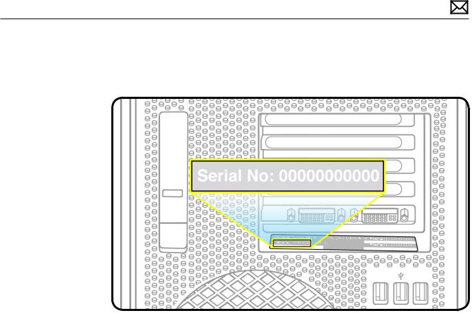
Serial Number Location
The Mac Pro (Early 2009) serial number is located on the configuration label, directly below the configuration description.
2010-06-03 |
Mac Pro (Early 2009) Basics — Overview 13 |

Apple Technician Guide
Troubleshooting
Mac Pro (Early 2009)
© 2009 Apple Inc. All rights reserved.

General Troubleshooting
Update System Software
Important:Whenever possible before beginning troubleshooting, ensure the latest software and firmware updates have been applied.
Troubleshooting Theory
For general information on troubleshooting theory, refer to:
http://service.info.apple.com/service_training/en/006/troubleshoot/index.php?page=intro
Emerging Issues
For the latest on troubleshooting issues, refer to:
http://support.apple.com/kb/index?page=search&q=khot%20Mac%20Pro%20 Emerging%20Issue
Hardware vs. Software
For information on how to isolate a hardware issue from a software issue, refer to:
http://support.apple.com/kb/TS1388?viewlocale=en_US
TS1394—Mac OS X:Troubleshooting installation and software updates <http://support.apple. com/kb/TS1394>
HT2956—Troubleshooting Mac OS X installation from CD or DVD <http://support.apple.com/ kb/HT2956>
For information on how to troubleshoot a software issue, refer to:
HT1199—Mac OS X:How to troubleshoot a software issue <http://support.apple.com/kb/ HT1199>
2010-06-03 |
Mac Pro (Early 2009) General Troubleshooting — Update System Software 15 |

Mac Pro Firmware Updates
Firmware is the name given to software that is written into memory circuits, such as flash memory, that will hold the software code indefinitely, even when power is removed from the hardware. Firmware on Intel Mac computers is designed to be updated if necessary through a software update.
EFI firmware updates update the Boot ROM, and SMC updates update the System Management Controller firmware.The SMC manages fans and other environmental parameters that are independent of the Boot ROM.
Firmware symptoms can be easily mistaken for hardware issues (e.g., overheating issues, fan noise issues, etc.). Always check both EFI and SMC firmware versions and update if necessary before replacing any hardware components.
The following lists describe the type of symptoms that may be resolved by updating the EFI and SMC firmware.
Symptoms that may be resolved by updating EFI firmware:
•Cannot eject media (various conditions)
•No video on start up
•Blue system failure screens in Windows XP/Vista
•Not waking or sleeping when expected
•Bad media taking too long to eject (including holding mouse button down at startup taking minutes to eject)
Symptoms that may be resolved by updating SMC firmware:
•Fan related behavior (excessive speed or noise)
•Loud audible clicking from some fans
•Thermal shut down or warnings
•Diagnostics reporting failures
•Sleep/wake issues
•Intermittent shut down
•SMC causes bad/missing ambient sensor to cause the computer to go to sleep
•Hangs, black screen on restart from Windows
•Quick power cycle causes Memory Processor Board Diagnostic LEDs and CPU Overtemp LEDs to illuminate solidly
Important: Since the SMC firmware is stored on both the backplane board and processor board, it is important that the version of SMC firmware match on both boards.
Please follow the steps outlined in KnowledgeBase article 303364,“About Firmware Updates for Intel-based Macs,”to perform an EFI and/or SMC firmware update. Information about firmware versions for Intel Macs can be found in KnowledgeBase article 303880,“Mac OS X: Firmware Updates for Intel-based Macs.”
2010-06-03 |
Mac Pro (Early 2009) General Troubleshooting — Mac Pro Firmware Updates 16 |
Memory Configuration
Mac Pro (Early 2009) comes with a minimum of 3 GB of memory, installed as three 1 GB unbuffered dual inline memory modules (UDIMMs).
DIMMs must fit these specifications:
•PC3-8500,1066 MHz, DDR3 SDRAM UDIMMs
•72-bit wide, 240-pin modules
•18 memory ICs maximum per UDIMM
•Error-correcting code (ECC)
For proper operation of Mac Pro (Early 2009) computers, Apple recommends using only Appleapproved DIMMs. Refer to GSX for Apple DIMM service part numbers. Memory from older Macintosh computers is not compatible with Mac Pro (Early 2009).
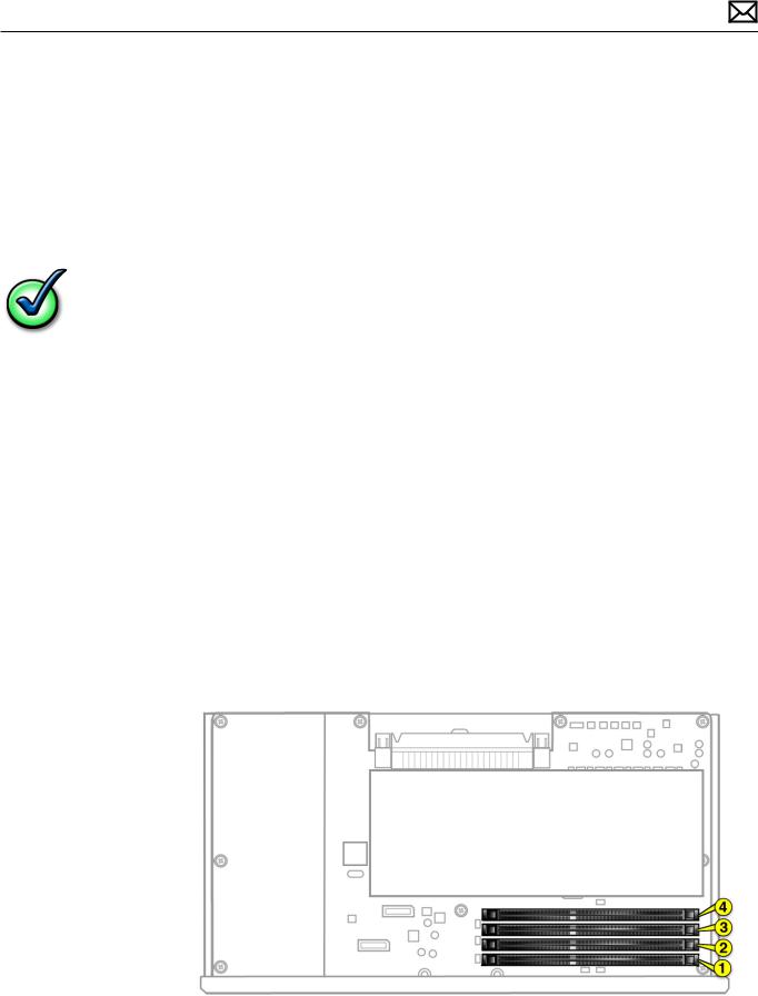
Quad Core
Quad-core computers have four memory slots.You can install 1 GB or 2 GB DIMMs for a total of up to 8 GB of memory.
You can install different size DIMMs in Mac Pro (Early 2009). However, for best performance, Apple recommends you install equal-size DIMMs (all 1 GB or all 2 GB) filling the slots in the order listed in this table. Note that you cannot place a DIMM in slot 4, without first placing a DIMM in slot 3.
|
If you have |
Fill these slots |
|
Two DIMMs |
1 and 2 |
|
Three DIMMs |
1, 2, and 3 |
|
Four DIMMs |
1, 2, 3, and 4 |
See also“Memory Slot Utility”below. |
|
|
2010-06-03 |
Mac Pro (Early 2009) General Troubleshooting — Memory Configuration 17 |
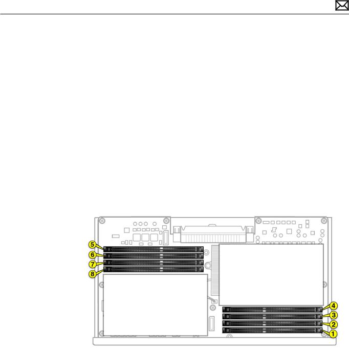
8 Core
Eight-core computers have eight memory slots.You can install 1 GB, 2 GB, or 4 GB DIMMs for a total of up to 32 GB of memory.
You can install different size DIMMs in Mac Pro (Early 2009). However, for best performance, Apple recommends you install equal-size DIMMs (all 1, 2, or 4 GB) filling the slots in the order listed in this table. Note that you cannot place a DIMM in slot 4, without first placing a DIMM in slot 3; you also cannot place a DIMM in slot 8 without a DIMM in slot 7.
If you have |
Fill in these slots |
Two DIMMs |
1 and 2 |
Three DIMMs |
1, 2, and 3 |
Four DIMMs |
1, 2, and 5, 6 |
Six DIMMs |
1, 2, 3 and 5, 6, 7 |
Eight DIMMs |
1, 2, 3, 4 and 5, 6, 7, 8 |
|
|
See also“Memory Slot Utility”below.
Memory Slot Utility
If you install different size DIMMs in quad-core or 8-core processor Mac Pro (Early 2009) computers, follow the order in the tables above. If the DIMM configuration you install doesn’t provide optimized performance, the Memory Slot Utility will appear on screen and recommend an improved configuration.To use the Memory Slot Utility again, go to /System/Library/Core Services.
2010-06-03 |
Mac Pro (Early 2009) General Troubleshooting — Memory Configuration 18 |
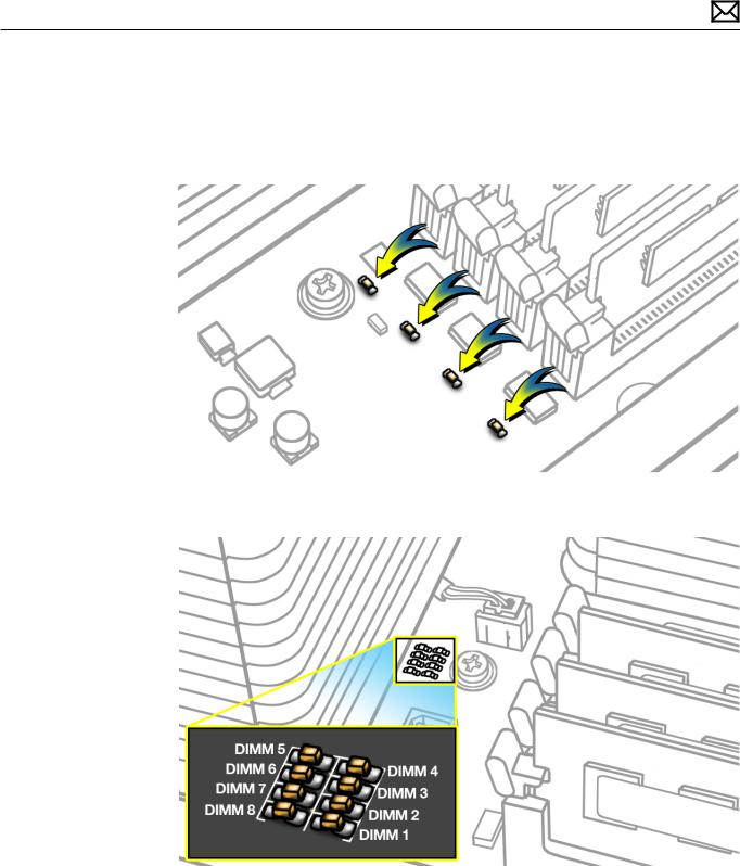
Memory Diagnostic LEDs
The 8-core and quad-core processor boards include a set of diagnostic memory LEDs.The following illustrations show the location of each LED and its associated DIMM slot.
Quad Core
8 Core
To diagnose memory issues, start up the computer and check the diagnostic memory LEDs. An illuminated, red LED indicates its associated DIMM may be poorly seated or failed.
Note that Apple System Profiler does not report unseated or failed memory.You must use the memory LEDs to locate DIMM issues.
2010-06-03 |
Mac Pro (Early 2009) General Troubleshooting — Memory Diagnostic LEDs 19 |
Troubleshooting Memory LEDs
Follow this procedure when troubleshooting each DIMM identified by a red LED:
1.Remove and reseat DIMM.
2.Restart computer. If associated LED is no longer illuminated, issue is resolved.
3.If associated LED remains illuminated, replace DIMM with new DIMM.
4.Restart computer and verify LED is no longer illuminated.
There is one exception. If two LEDs illuminate at the same time for the 3 DIMM and 4 DIMM slots or for the 7 DIMM and 8 DIMM slots, check both DIMMs using this process:
Check |
Result |
Action |
|
|
|
|
|
1. |
Remove both DIMMs identified by |
Yes |
Replace DIMM 3 (or DIMM 7) with |
|
illuminated LEDs. Set DIMM 4 (or |
|
new DIMM. Go to step 2. |
|
DIMM 8) aside, and reseat DIMM 3 (or |
|
|
|
DIMM 7). Restart computer. Is DIMM 3 |
|
|
|
No |
Go to step 2. |
|
|
(or DIMM 7) LED illuminated? |
||
|
|
|
|
|
|
|
|
2. |
Reinstall DIMM 4 (or DIMM 8). Restart |
Yes |
Replace DIMM 4 (or DIMM 8) with |
|
computer. Is one or both LEDs |
|
new DIMM. |
|
illuminated? |
|
|
|
|
|
|
|
|
No |
Issue resolved. |
|
|
|
|
2010-06-03 |
Mac Pro (Early 2009) General Troubleshooting — Memory Diagnostic LEDs 20 |
PCIe/Graphics Cards
The Mac Pro (Early 2009) backplane board includes one double-wide PCI Express (PCIe) graphics slot and three PCIe expansion slots, for a total of four slots.The computer comes with a graphics card installed in slot 1.You can install additional PCIe graphics and expansion cards in the remaining three expansion slots.
All four slots physically support cards of up to x16 slot width.
Slot electrical specifications:
•Slots 1 and 2: x16 PCIe 2.0
•Slots 3 and 4: x4 PCIe 2.0
Important: Graphics cards from previous Power Mac G5 and Mac Pro models are not softwarecompatible with Mac Pro (Early 2009) models.
Important: Combined maximum power consumption for all four PCIe slots must not exceed 300 W.
2010-06-03 |
Mac Pro (Early 2009) General Troubleshooting — PCIe/Graphics Cards 21 |
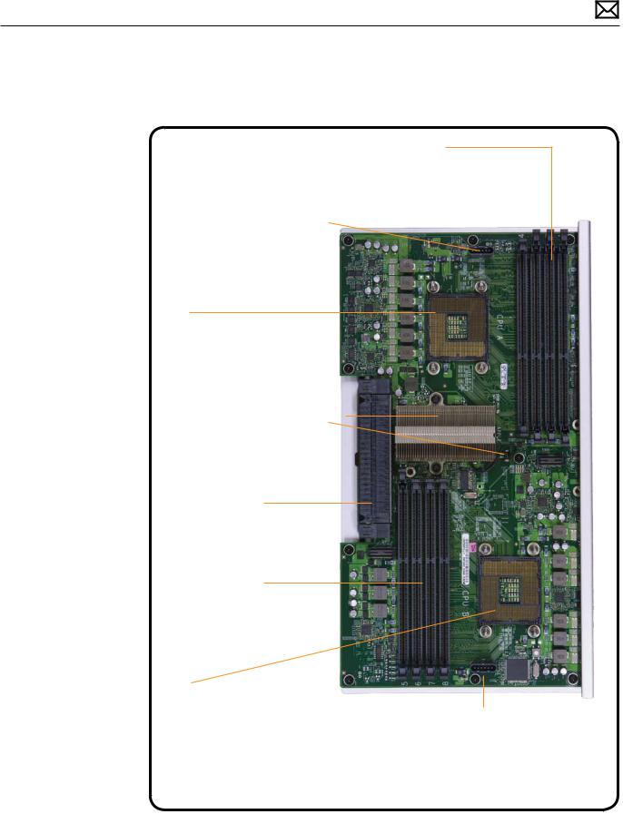
Functional Overview
Processor Board
Memory Slots 4-1
* Power and fans, no boot/video * Kernel panic
* Reduced or slow system performance * Thermal issues
* Frequent application crashes
CPU A Heatsink Fan and Thermal Sensor
*Intermittent shutdown
*Freezes
*Noisy or fast fans
*Slow or reduced performance
CPU A
*Power & Fans, no boot/video
*Freezes
*Kernel panic
Northbridge, Heatsink and
Thermal Sensor
*Intermittent shutdown
*Freezes or unstable system
*Noisy or fast fans
*Slow or reduced performance
Backplane Interconnect
*No power
*No boot
*Intermittent freezes
*Kernel panic
Memory Slots 5-8
(Dual CPU configuration only)
*Kernel panic
*Reduced or slow system performance
*Thermal issues
*Frequent application crashes
CPU B
(Dual CPU configuration only)
*Only 1 CPU detected by system
*Freezes
*Kernel panic
CPU B Heatsink Fan and Thermal Sensor
(Dual CPU configuration only)
*Intermittent shutdown
*Freezes
*Noisy or fast fans
*Slow or reduced performance
2010-06-03 |
Mac Pro (Early 2009) General Troubleshooting — Functional Overview 22 |
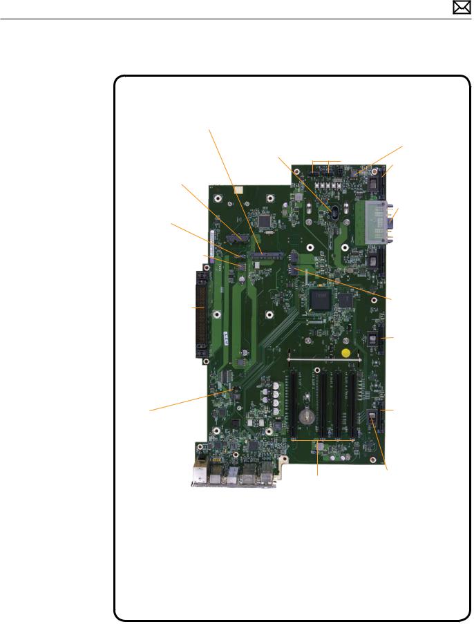
Backplane Board
Front Panel Board (including front USB, FireWire and headphone ports)
*No power
*Connectivity issues with front ports
*No audio
*Intermittent power off
AirPort
*AirPort not detected in System Profiler
*Kernel panic on boot or wi-fi data transfer
Internal Speaker
*No boot chime
*No or distorted sound
Processor Cage Fan - Front
*Intermittent shutdown
*Freezes
*Fast or noisy fans
*System runs hot
Backplane Interconnect
*No Power
*No boot
*Intermittent freezes
*Kernel Panic
Processor Cage Fan - Rear 
*Intermittent shutdown
*Freezes
*Fast or noisy fans
PCIe Fan
*Intermittent shutdown
*Freezes, graphics glitches
*Fast or noisy fans
*System runs hot
Optical Drive
Power and SATA
*Optical drive(s) not detected in System Profiler
*No startup from DVD
Optical Drive and
Power Supply Fan
*Intermittent shutdown
*Freezes
*Fast or noisy fans
*System runs hot
SATA Hard Drive 1
*Hard drive not detected in System Profiler
*No startup from hard drive
*Boot to flashing ?
DC Power Supply connection
*No power
*Intermittent power-off
*Power-off during heavy CPU/GPU/PCI load
 SATA Hard Drive 2
*Hard drive not detected in System Profiler
*Hardware RAID issues
PCI Aux Power
*No video (where required PCIe video cards)
*PCI cards not detected
SATA Hard Drive 3
*Hard drive not detected in System Profiler
*Hardware RAID issues
Bluetooth
*Bluetooth not detected in System Profiler
*Intermittent Bluetooth availability
*Data transfer or pairing issues
E |
A |
|
|
|
net the Gigabitr |
udio Analogue |
udio ital DiA g |
800 e ewi Fir r |
0.2 USB |
PCIe Slots 1-4
*No video
*Freezes or unstable system
*Freezes during boot
*Kernel panic
*No hardware RAID (No boot)
SATA Hard Drive 4
*Hard drive not detected in System Profiler
*Hardware RAID issues
Hard Drive Thermal Sensors (1 per drive)
*Intermittent shutdown
*Freezes or unstable system
*Noisy or fast fans
*Slow or reduced performance
*Drive spin-down
2010-06-03 |
Mac Pro (Early 2009) General Troubleshooting — Functional Overview 23 |
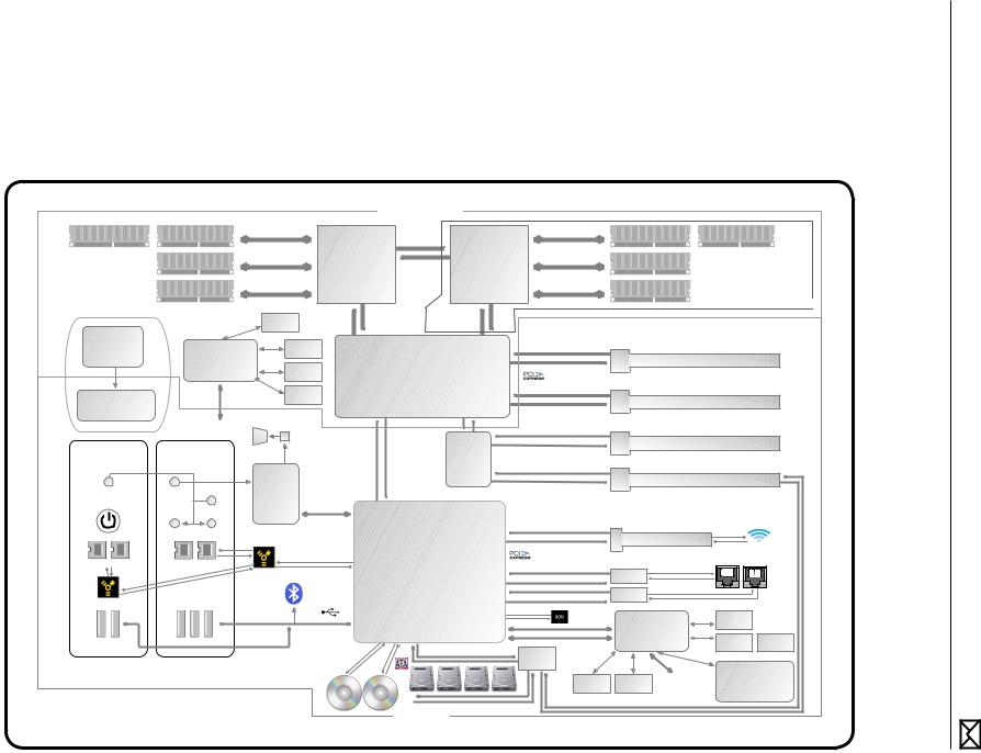
03-06-2010
24 Diagram Block — Troubleshooting General 2009) (Early Pro Mac
|
|
|
|
PROCESSOR BOARD |
|
|
|
|
|
||
3 |
4 |
Ch 2 |
|
Port 1 |
QPI |
Port 1 |
|
Ch 2 |
|
8 |
7 |
|
|
CPU A |
CPU B |
|
|
|
|||||
|
|
DDR3 1066 MHz |
Xeon |
|
|
|
Xeon |
|
DDR3 1066 MHz |
|
|
|
2 |
|
|
|
|
|
|
6 |
|
||
DIMMs |
Ch 1 |
|
|
20 Lanes Each |
|
|
Ch 1 |
|
|
||
|
3 Channels |
|
|
|
|
|
3 Channels |
|
DIMMs |
||
|
|
|
Direction |
|
|
|
|
||||
Slots |
|
1 or 2 DIMM Slot/Channel |
Quad Core |
|
|
Quad Core |
|
1 or 2 DIMM Slot/Channel |
|
||
1 |
25 GB/s Peak Bandwidth |
|
6.4GT/s |
|
|
25 GB/s Peak Bandwidth |
5 |
Slots |
|||
|
2.93 GHz |
|
|
|
2.93 GHz |
|
|||||
|
|
Ch 0 8MB Shared L2 Cache |
|
8MB Shared L2 Cache Ch 0 |
|
|
|
||||
|
|
|
Port 0 |
|
|
|
Port 0 |
|
|
|
8-Core PROCESSOR BOARD Only |
|
|
|
QPI |
|
|
|
|
|
|
||
|
|
Current |
|
|
QPI |
|
|
|
|
||
|
|
|
20 Lanes Each Direction 20 Lanes Each Direction |
|
|
|
|
||||
|
|
Monitor |
|
6.4GT/s |
|
6.4GT/s |
|
|
|
|
|
Main Clock |
Secondary |
Temp |
x20 QPI |
|
|
|
x20 QPI |
|
16 Lanes Each Direction |
|
|
Port 0 |
|
|
|
Port 1 |
|
|
|
||||
|
|
|
|
|
|
|
|
|
PCIe Gen2 5GT/s |
|
|
Generator |
System |
Sensors |
|
|
|
|
Port |
|
|
1 |
|
|
Management |
|
|
|
|
|
3-6 |
|
10GB/s Bandwidth |
x16 Gen2 PCIe Slot |
|
|
Voltage |
|
|
|
|
|
|
|
|||
|
|
North Bridge |
|
|
|
|
|
|
|||
|
Controller |
Monitor |
|
|
2 x16 |
|
|
|
|
||
|
|
|
|
|
|
|
PCIe |
|
PCIe Gen2 5GT/s |
|
|
|
|
|
|
|
|
|
|
|
|
|
|
|
To |
Fans |
|
|
|
|
Port |
|
16 Lanes Each Direction |
|
|
PCIe Clock |
Primary |
|
|
|
|
|
|
2 |
|
||
|
|
|
|
|
7-10 |
|
10GB/s Bandwidth |
x16 Gen2 PCIe Slot |
|||
SMC |
|
|
|
|
|
|
|||||
Buffer |
|
|
x4 ESI/DMI |
|
|
Port |
|
|
|
|
|
|
Internal |
|
x4 PCIe 1-2 |
|
|
|
|
||||
|
|
|
|
|
|
|
|||||
|
|
|
|
|
|
|
|
|
|
|
|
|
|
Speaker |
|
|
PCIe Gen2 5GT/s |
|
|
|
|
|
|
|
|
|
|
4 Lanes Each Direction |
|
|
|
PCIe Gen2 5GT/s |
|
|
|
|
|
|
|
|
|
|
|
|
|
||
|
|
|
|
|
|
|
|
|
4 Lanes Each Direction |
|
|
|
|
|
|
|
|
|
|
|
2.5GB/s Bandwidth |
3 |
x4 Gen2 PCIe Slot |
|
|
|
|
|
|
PCIe |
|
|
|||
Front I/O on |
Rear I/O Panel |
|
PCIe Gen1 2.5GT/s |
|
|
|
|
|
|
||
enclosure |
|
4 Lanes Each Direction |
|
|
Switch |
|
|
|
|
||
|
|
1.25GB/s Bandwidth |
|
|
|
PCIe Gen2 5GT/s |
|
|
|||
|
|
|
|
|
|
|
|
|
4 Lanes Each Direction |
|
|
|
|
HD |
|
|
|
|
|
|
2.5GB/s Bandwidth |
4 |
x4 Gen2 PCIe Slot / RAID |
|
|
|
|
|
|
|
|
|
|||
Headphone |
Digital |
|
|
|
|
|
|
|
|
|
|
Audio |
|
|
|
|
|
|
|
|
|
||
/Mic/iPhone |
In |
|
|
|
|
|
|
|
|
|
|
Codec |
|
|
|
|
|
|
|
|
|
||
support |
Line In |
x4 ESI/DMI |
|
|
|
|
|
|
|
||
|
|
|
|
|
|
|
|
|
|
|
|
|
Power |
|
|
|
|
|
|
|
|
|
|
|
|
|
|
|
Button/ |
|
|
|
|
|
|
|
|
|
PCIe Gen1 2.5GT/s |
|
|
|
|
|
SIL |
Digital Out |
Line Out |
|
GPIOs |
|
|
x1 |
|
1 Lane Each Direction |
|
|
|
|
|
|
|
|
|
|
|
|
|
|
|
|
|||||
|
|
|
|
|
FW |
|
|
|
PCIe |
Port 6 |
0.3GB/s Bandwidth |
x1 Gen1 MiniPCIe Slot |
|
|
|
|
|
|
|
|
|
|
|
|
|
|
|
|
|
Airport |
|
|
|
|
|
|
PCIe Gen1 2.5GT/s |
|
|
|
|
|
|
|
|
|
|
|
|
|
|
|
1 Lane Each Direction |
|
|
|
|
|
|
|
|
Ethernet |
|
|
|
|
|
|
0.3GB/s Bandwidth |
|
|
|
|
|
|
|
|
|
|
|
|
|
|
|
|
|
|
|
|
|
|
|
10/100/1000 Mbit |
||
FW800 |
FW800 |
FW800 |
FW800 |
|
Port 5 x1 |
South Bridge |
|
|
PCIe Gen1 2.5GT/s |
|
|
||||
|
|
|
|
|
|
|
|||||||||
|
|
|
|
|
|
PCIe |
|
|
1 Lanes Each Direction |
|
|
|
|
||
|
|
|
|
|
|
|
|
|
|
|
Gb Enet A |
|
|
|
|
|
|
|
|
|
Bluetooth 2.1 |
|
|
|
x4 |
Port 3 |
0.3GB/s Bandwidth |
|
1 |
2 |
|
|
|
|
|
FW800 |
|
|
|
|
|
||||||
|
|
|
|
|
|
|
|
PCIe |
|
|
|
|
|
|
|
|
|
|
|
|
|
PECI 2.0 |
|
|
|
|
Gb Enet B |
|
|
|
|
Port |
|
Port |
|
|
|
|
Port 4 |
|
|
|
|
||||
|
Port 10 |
|
|
|
|
|
|
|
|
|
|
||||
9 |
4 |
0 |
7 |
2 |
|
|
|
|
|
|
|
|
|
|
|
|
|
|
|
|
|
|
|
|
|
|
|||||
|
|
|
|
|
|
|
|
|
|
SPI |
4MB |
|
|
Temp |
|
|
|
|
|
|
|
|
|
|
|
|
Primary System |
|
|||
|
|
|
|
|
|
USB 2.0 |
(2 EHCI, 12 ports) |
|
|
I2C |
|
Sensors |
|
||
|
|
|
|
|
|
SATA 3 Gbps (6 channels) |
|
|
Management |
|
|
|
|||
|
|
|
|
|
|
|
LPC |
|
|
Voltage |
Current |
||||
USB 2.0 |
|
USB 2.0 |
|
Port 0 |
Port 1 Port 2 - 5 (to Bay 1 - 4) |
|
|
Controller |
|
||||||
|
|
|
|
|
|
||||||||||
|
|
|
|
|
|
|
4 channels @ 0.3 GB/s Bandwidth each |
|
|
|
Monitor |
Monitor |
|||
|
|
|
|
|
|
|
SATA/ |
|
|
|
|
||||
|
|
|
|
|
|
|
|
|
|
|
|
|
|
|
|
|
|
|
|
|
|
|
|
|
|
|
SAS Mux |
|
|
Power Supply |
|
|
|
|
|
|
|
|
1 |
2 |
3 |
4 |
|
Power |
To |
||
|
|
|
|
|
|
|
Fans |
Secondary |
80A @ 12V (S0) |
||||||
|
|
|
|
|
|
|
|
|
|
|
|||||
|
|
|
|
|
Optical |
Optical |
|
|
|
|
button/SIL |
SMC |
5A @ 5V (S5) |
||
|
|
|
|
|
Drive |
Drive |
|
|
|
|
|
|
|
||
|
|
|
|
|
Top |
Bottom |
|
|
|
|
|
|
|
|
|
|
|
|
|
|
|
|
|
1 0.3 GB/s channel to each drive |
4 channels @ 0.3 GB/s Bandwidth each |
|
|
|
|||
|
|
|
|
|
|
|
|
|
|
|
|
|
|||
BACKPLANE
Diagram Block

Common Reset Procedures
The following reset procedures are often helpful in troubleshooting Mac Pro issues.
Resetting the System Management Controller (SMC)
The System Management Controller (SMC) controls all power functions for the computer. If the computer is experiencing any power issue, resetting the SMC may resolve it.The SMC controls several functions, including:
•Telling the computer when to turn on, turn off, sleep, wake, idle, and so forth
•Handling system resets from various commands
•Controlling the fans
It is also recommended that the SMC be reset after a backplane board or processor board is replaced as part of a repair.
Note that resetting the SMC does not reset the PRAM. Resetting the SMC will not resolve issues in which the computer is unresponsive—in these situations, restarting the computer will generally suffice. If the computer isn’t responding, perform these steps one at a time, in the following order, until the issue has been resolved:
1.Force Quit (Option-Command-Escape)
2.Restart (Control-Command-Power)
3.Force Shut Down (press the power button for 10 seconds)
Resetting the SMC can resolve some computer issues such as not starting up, not displaying video, sleep issues, fan noise issues, and so forth. If the computer still exhibits these types of issues after you’ve restarted the computer, try resetting the SMC by removing AC power:
1.From the Apple menu, choose Shut Down (or if the computer is not responding, hold the power button until it turns off).
2.Unplug the AC power cord.
3.Wait at least 15 seconds.
4.Plug the power cord back in, making sure the power button is not being pressed at the time.
5.Press the power button to start up the computer.
For more information:
http://www.apple.com/support
HT1411—Mac Pro:How to reset the System Management Controller (SMC) <http:// support.apple.com/kb/HT1806>
2010-06-03 |
Mac Pro (Early 2009) General Troubleshooting — Common Reset Procedures 25 |

Resetting the Parameter RAM (PRAM)
To reset PRAM:
1.If the computer is on, turn it off.
2.Locate the following keys on the keyboard:Command, Option, P, and R.You will need to hold these keys down simultaneously in Step 4.
3.Turn on the computer.
4.Press and hold the Command-Option-P-R keys.
Important: You must press this key combination before the gray screen appears.
5.Hold the keys down until the computer restarts and you hear the startup sound for the second time.
6.Release the keys.
For more information:
http://www.apple.com/support
HT1379—Resetting your Mac’s PRAM and VRAM <http://support.apple.com/kb/HT1379>
Starting Up in Safe Mode
A Safe Boot is a special way to start Mac OS X when troubleshooting.To start up into Safe Mode (Safe Boot):
1.Make sure the computer is shut down.
2.Press the power button.
3.Immediately after you hear the startup tone, press and hold the Shift key.
Note: The Shift key should be held as soon as possible after the startup tone but not before.
4.Release the Shift key when you see the screen with the gray Apple and progress indicator (looks like a spinning gear). During startup, ”Safe Boot”appears on the Mac OS X startup screen.To leave Safe Mode, restart the computer normally, without holding down any keys during startup.
For more information:
http://www.apple.com/support
HT1564—What is Safe Boot, Safe Mode? <http://support.apple.com/kb/HT1564>
TS1884—Safe Boot take longer than normal startup <http://support.apple.com/kb/ TS1884>
2010-06-03 |
Mac Pro (Early 2009) General Troubleshooting — Common Reset Procedures 26 |

Real Time Clock (RTC) Reset
The Real Time Clock (RTC) is a chip on the backplane board that controls the date and time functions of the computer. If the computer is experiencing an issue booting, resetting the RTC may resolve it. Follow these steps to reset the RTC:
1.From the Apple menu, choose Shut Down (or if the computer is not responding, hold the power button until it turns off).
2.Unplug the AC power cord.
3.Remove the battery for at least 20 seconds.You may need to remove a PCI Express card to have access to the battery.
Alternatively, you can reset RTC by pressing the RTC reset button (small button located next to the battery). Press the button for one second when the computer is shut down but still connected to AC power.
Power-On Self Test: RAM and Processor Verification
A power-on self test in the computer’s ROM automatically runs whenever the computer is started up after being fully shut down (the test does not run if the computer is only restarted). If the test detects a problem, the status LED located above the power button on the front of the computer will flash in the following ways*:
•1 Flash:No RAM is installed or detected. Or, the quick memory test failed. An LED will light up on the processor board next to the affected DIMM or empty DIMM slot.
•3 Flashes:A RAM bank failed extended memory testing. An LED will light up on the processor board corresponding to the affected DIMM.
Troubleshooting:Try reseating the memory DIMMs. Check memory installation instructions for proper installation order. Swap affected DIMM with known good DIMM.
*Note: The status LED lights up when the power button is depressed at startup. Do not count this light as one of the diagnostic flashes.The memory processor board diagnostic LEDs will also flash briefly when the computer is started up or shut down and when it goes in and out of sleep mode.This is normal behavior.
2010-06-03 |
Mac Pro (Early 2009) General Troubleshooting — Power-On Self Test:RAM and Processor Verification 27 |

Minimum Configuration Testing
The following procedure can help you troubleshoot a“No Power”or other startup related symptom.
Using this method of gradually building the system up from a bare minimum and verifying expected behaviors at each step is one way of determining which modules function together in some limited form.The goal is to identify which module(s) cause a symptom to recur when they are added. Alternatively, the method may help you discover a loose or faulty cable or connector.
If you encounter unexpected behavior at a step, the general rule of thumb is to suspect the last module you re-installed. Backtrack to the previous step, remove the last installed module, and re-verify the expected behavior.
Note: As with any troubleshooting method, minimum configuration testing is not practical for every repair. Refer to other troubleshooting sections provided in this manual for additional direction in troubleshooting.
Take Mac Pro Down to Minimum Configuration
1. Remove the following items from the Mac Pro:
•Hard drives
•Optical drives
•Processor tray and processor board (containing processors, processor heatsinks, and memory)
•PCIe cards
•AirPort card
•Bluetooth card
•Battery
•PCIe fan
•Processor cage (including fans)
•Front panel board
Disconnect all cables from the backplane board, except the power supply.
2010-06-03 |
Mac Pro (Early 2009) General Troubleshooting — Minimum Configuration Testing 28 |
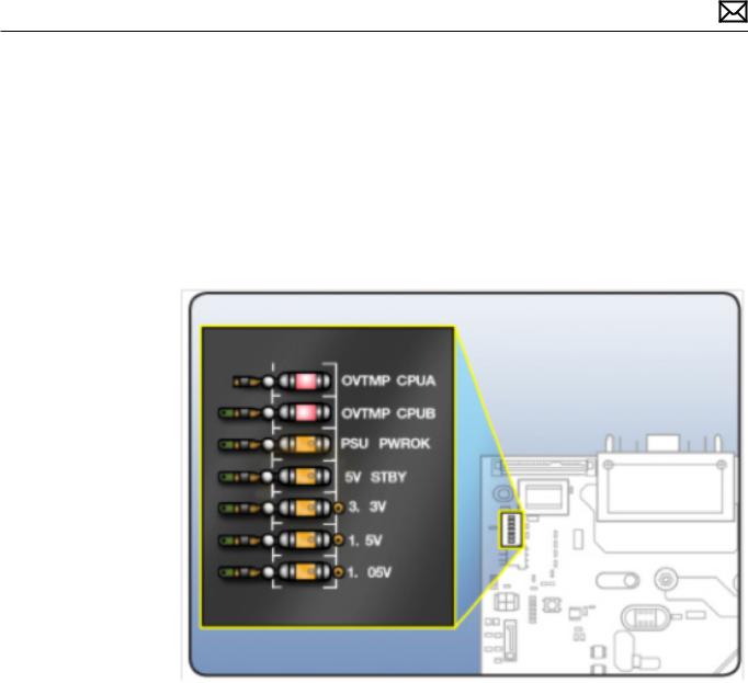
2. Attach a known good power cord from a known good AC source to the Mac Pro.
Note: When connecting the Mac Pro to AC power, verify that the LEDs for OVTMP CPUA and OVTMP CPUB briefly flash red (less than 0.5 sec).The LEDs are located under hard drive bay 1 on the backplane board. If they do not illuminate briefly, there is an issue with either the power supply or the backplane board. Generally speaking, power supplies, because of their nature, can be affected by issues more than other modules. If you suspect a power supply has failed,verify it in another Mac Pro (Early 2009), if available, before replacing any modules.
Note: The OVTMP CPUA and OVTMP CPUB LEDs on a properly functioning Mac Pro will also momentarily flash red immediately after the Mac Pro is disconnected from AC power.
3. Press the DIAG button, and verify 5V STBY LED (amber) illuminates.
Expected behavior:
5V STBY LED illuminates, confirming power to the backplane board. If the LED does not illumuniate, suspect power supply or backplane board failure.
4.Disconnect AC power cord. Reinstall processor cage with fans and processor board. Do not reinstall processor(s), heatsinks, or memory.
Notes:
•Verify no bent pins on processor connector or mating connector of processor board and backplane board.
•Verify no grime or foreign debris is causing contact issues on processor connectors, and connectors on processor board and backplane board.
5. Connect AC power cord. Press the DIAG button to verify the 5V STBY LED illuminates.This is
2010-06-03 |
Mac Pro (Early 2009) General Troubleshooting — Minimum Configuration Testing 29 |
a verify step, as you’ve added modules since previous step.
Expected behavior:
5V STBY LED illuminates, confirming power to the backplane board. If the LED does not illumuniate, suspect power supply or backplane board failure.
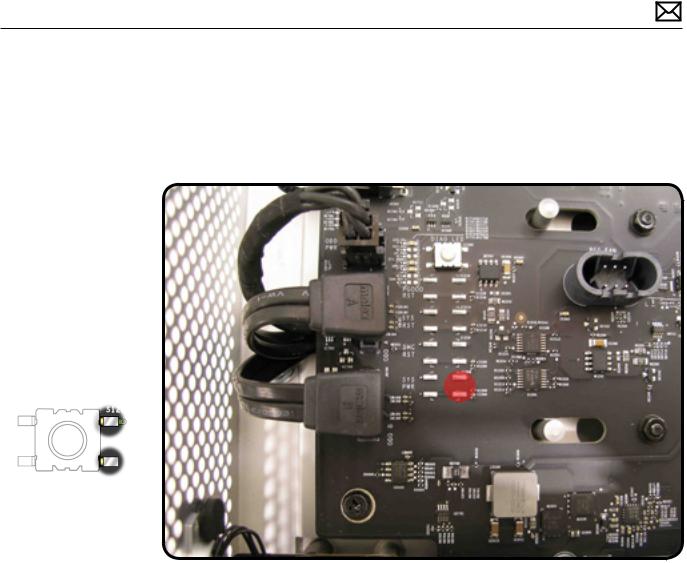
6. Momentarily jump the SYS_PWR solder pads to turn ON the Mac Pro.
Expected behavior:
•Front and rear processor cage fans (and PCIe fan, if installed) should spin slowly
•One red-colored error LED illuminates on the processor board (next to the memory slots).
Notes:
•The solder pads are at the same location where the power button would be.
•To help troubleshoot processor issues, check the related CPU Error LED. See“Processor Diagnostic LEDs.”
7. Press and hold the DIAG button.
Expected behavior:
•PSU PWROK (green), 5V STBY (amber), EFI DONE (green), GPU OK (green) LEDs illuminated
•No startup tone
•Front and rear processor cage fans (and PCIe fan, if installed) should spin slowly
8. Disconnect AC power cord.
At this point, if the Mac Pro powers ON using a known good front panel board, power button, and cable, make your testing easier by using it instead of jumpering SYS_PWR solder pads.
2010-06-03 |
Mac Pro (Early 2009) General Troubleshooting — Minimum Configuration Testing 30 |
Loading...