


D e v e l o p e r N o t e
PowerBook G4
November 2002
Apple Computer, Inc.
© 2001, 2002 Apple Computer, Inc. All rights reserved.
No part of this publication may be reproduced, stored in a retrieval system, or transmitted, in any form or by any means, mechanical, electronic, photocopying, recording, or otherwise, without prior written permission of Apple Computer, Inc., with the following exceptions: Any person is hereby authorized to store documentation on a single computer for personal use only and to print copies of documentation for personal use provided that the documentation contains Apple’s copyright notice.
The Apple logo is a trademark of Apple Computer, Inc.
Use of the “keyboard” Apple logo (Option-Shift-K) for commercial purposes without the prior written consent of Apple may constitute trademark infringement and unfair competition in violation of federal and state laws.
No licenses, express or implied, are granted with respect to any of the technology described in this book. Apple retains all intellectual property rights associated with the technology described in this book. This book is intended to assist application developers to develop applications only for Apple-labeled or Apple-licensed computers.
Every effort has been made to ensure that the information in this document is accurate. Apple is not responsible for typographical errors.
Apple Computer, Inc. 1 Infinite Loop Cupertino, CA 95014 408-996-1010
Apple, the Apple logo, AirPort, FireWire, iMac, Mac, PowerBook, and Macintosh are trademarks of Apple Computer, Inc., registered in the United States and other countries.
iBook, SuperDrive, and Velocity engine are trademarks of Apple Computer, Inc.
Adobe is a trademark of Adobe Systems Incorporated or its subsidiaries and may be registered in certain jurisdictions.
OpenGL is a registered trademark of Silicon Graphics, Inc.
PowerPC is a trademark of International Business Machines Corporation, used under license therefrom.
Simultaneously published in the United States and Canada.
Even though Apple has reviewed this manual, APPLE MAKES NO WARRANTY OR REPRESENTATION, EITHER EXPRESS OR IMPLIED, WITH RESPECT TO THIS MANUAL, ITS QUALITY, ACCURACY, MERCHANTABILITY, OR FITNESS FOR A PARTICULAR PURPOSE. AS A RESULT, THIS MANUAL IS SOLD “AS IS,” AND YOU, THE PURCHASER, ARE ASSUMING THE ENTIRE RISK AS TO ITS QUALITY AND ACCURACY.
IN NO EVENT WILL APPLE BE LIABLE FOR DIRECT, INDIRECT, SPECIAL, INCIDENTAL, OR CONSEQUENTIAL DAMAGES RESULTING FROM ANY DEFECT OR INACCURACY IN THIS MANUAL, even if advised of the possibility of such damages.
THE WARRANTY AND REMEDIES SET FORTH ABOVE ARE EXCLUSIVE AND IN LIEU OF ALL OTHERS, ORAL OR WRITTEN, EXPRESS OR IMPLIED. No Apple dealer, agent, or employee is authorized to make any modification, extension, or addition to this warranty.
Some states do not allow the exclusion or limitation of implied warranties or liability for incidental or consequential damages, so the above limitation or exclusion may not apply to you. This warranty gives you specific legal rights, and you may also have other rights which vary from state to state.
Contents
|
Figures and Tables |
7 |
|
||
Preface |
About This Developer Note |
9 |
|||
|
|
|
|
||
|
Contents of This Note |
9 |
|
||
Chapter 1 |
Introduction |
11 |
|
||
|
|
|
|
|
|
|
New Features |
11 |
|
|
|
|
Features |
12 |
|
|
|
|
Appearance |
|
15 |
|
|
Peripheral Devices |
16 |
|
|
System Software |
17 |
|
|
Open Firmware |
17 |
|
|
Computer Identification |
18 |
|
|
Power-Saving Features |
18 |
|
|
Reduced Processor Speed |
18 |
||
Operating Modes |
18 |
|
|
Chapter 2 Architecture |
21 |
|
|
|
Block Diagram and Buses |
|
21 |
|
|
Block Diagram |
21 |
|
|
|
Main ICs and Buses |
23 |
|
|
|
Microprocessor and Caches |
23 |
|
||
PowerPC G4 Microprocessor |
23 |
|||
Level 2 Cache |
24 |
|
|
|
Level 3 Cache |
24 |
|
|
|
3
Apple Computer, Inc. November 2002
C O N T E N T S
Memory Controller and Bus Bridge |
24 |
||||
System RAM |
|
25 |
|
|
|
Boot ROM |
25 |
|
|
|
|
FireWire Controller |
26 |
|
|
||
Ethernet Controller |
26 |
|
|
||
Video Display Subsystem |
26 |
|
|||
I/O Controller |
28 |
|
|
|
|
DMA Support |
|
28 |
|
|
|
Interrupt Support |
28 |
|
|
||
USB Interface |
|
28 |
|
|
|
Ultra DMA/66 Interface |
29 |
|
|||
EIDE Interface |
|
29 |
|
|
|
Modem Support |
|
29 |
|
|
|
Sound Circuitry |
|
30 |
|
|
|
Power Controller |
|
30 |
|
|
|
AirPort Card Interface |
31 |
|
|||
CardBus Controller IC |
31 |
|
|||
Chapter 3 Devices and Ports |
|
33 |
|
|||
USB Ports |
33 |
|
|
|
|
|
USB Connectors |
33 |
|
|
|||
USB Storage Devices |
|
|
34 |
|
||
FireWire Port |
|
35 |
|
|
|
|
FireWire Connector |
|
35 |
|
|||
FireWire Device Programming |
37 |
|||||
Target Disk Mode |
|
37 |
|
|
||
Ethernet Port |
|
38 |
|
|
|
|
Internal Modem |
40 |
|
|
|
|
|
AirPort Card |
|
40 |
|
|
|
|
Data Security |
41 |
|
|
|
|
|
AirPort Hardware |
|
41 |
|
|
||
AirPort Software |
42 |
|
|
|||
Hard Disk Drive |
42 |
|
|
|
||
Hard Disk Dimensions |
42 |
|
||||
Hard Disk Connector |
|
44 |
|
|||
Signal Assignments |
|
45 |
|
|||
ATA Signal Descriptions |
46 |
|||||
4
Apple Computer, Inc. November 2002
C O N T E N T S
DVD-ROM/CD-RW Combo Drive |
48 |
|
|||||
DVD-R /CD-RW SuperDrive |
49 |
|
|
||||
Trackpad |
50 |
|
|
|
|
|
|
Keyboard |
50 |
|
|
|
|
|
|
Removing the Keyboard |
|
50 |
|
|
|||
Changing the Operation of the Keyboard |
51 |
||||||
Keyboard Illustrations |
|
51 |
|
|
|||
Using the Fn Key |
55 |
|
|
|
|||
Using the Num Lock Key |
55 |
|
|
||||
The Function-Keys Checkbox |
55 |
|
|||||
The Embedded Keypad |
|
57 |
|
|
|||
Other Control Keys |
58 |
|
|
|
|||
Flat-Panel Display |
|
59 |
|
|
|
|
|
External Monitors |
|
60 |
|
|
|
|
|
Dual Display and Mirror Mode |
60 |
|
|||||
Analog Monitor Resolutions |
61 |
|
|
||||
Digital Display Resolutions |
62 |
|
|
||||
DVI-I Connector |
62 |
|
|
|
|
||
External Video Port |
64 |
|
|
|
|
||
Sound System |
66 |
|
|
|
|
|
|
Sound Inputs |
67 |
|
|
|
|
||
Built-in Microphone |
67 |
|
|
||||
Audio Input Jack |
68 |
|
|
|
|
||
Modem Activity Sound Signals |
68 |
|
|||||
Sound Outputs |
|
68 |
|
|
|
|
|
Headphone Jack |
68 |
|
|
|
|
||
Internal Speakers |
69 |
|
|
|
|||
Digitizing Sound |
69 |
|
|
|
|
||
Chapter 4 Expansion Features |
71 |
RAM Expansion Slots 71 |
|
Getting Access to the Slots |
71 |
Mechanical Design of RAM SO-DIMMs 73
5
Apple Computer, Inc. November 2002
C O N T E N T S
Electrical Design of RAM SO-DIMMs |
73 |
SDRAM Devices 74 |
|
Configuration of RAM SO-DIMMs |
75 |
Address Multiplexing 75 |
|
RAM SO-DIMM Electrical Limits |
76 |
CardBus Slot 77 |
|
Appendix A Supplemental Reference Documents |
79 |
||||||
Apple Technical Notes |
79 |
|
|
|
|||
3D Graphics |
79 |
|
|
|
|
|
|
PowerPC G4 Microprocessor |
80 |
|
|
||||
Velocity Engine (AltiVec) |
80 |
|
|
||||
Mac OS X |
81 |
|
|
|
|
|
|
Mac OS 9.2.2 |
81 |
|
|
|
|
|
|
I/O Kit |
82 |
|
|
|
|
|
|
Open Firmware |
|
82 |
|
|
|
|
|
RAM Expansion Modules |
83 |
|
|
||||
PC Card Manager |
83 |
|
|
|
|||
ATA Devices |
84 |
|
|
|
|
|
|
USB Interface |
84 |
|
|
|
|
|
|
FireWire Interface |
85 |
|
|
|
|||
Digital Visual Interface |
86 |
|
|
|
|||
Wireless Networks |
|
86 |
|
|
|
||
Appendix B Abbreviations |
|
87 |
|
|
|
||
|
|
|
|||||
Abbreviations and Standard Units |
87 |
|
|||||
Other Abbreviations |
88 |
|
|
|
|||
Index |
91 |
|
|
|
|
|
|
|
|
|
|
|
|
|
|
6
Apple Computer, Inc. November 2002
Figures and Tables
Chapter 1 |
Introduction |
11 |
|
|
|
|
|
|
|
|
|
Figure 1-1 |
Front view of the computer |
15 |
|
|
|
|
|||
|
Figure 1-2 |
Back view showing I/O ports |
|
16 |
|
|
|
|||
|
Table 1-1 |
Feature changes |
|
12 |
|
|
|
|
|
|
Chapter 2 |
Architecture |
21 |
|
|
|
|
|
|
|
|
|
|
|
|
|
|
|
|
|
||
|
Figure 2-1 |
Block diagram |
22 |
|
|
|
|
|
||
|
Table 2-1 |
Buses supported by the Uni-N IC |
25 |
|
|
|
||||
Chapter 3 |
Devices and Ports |
33 |
|
|
|
|
|
|
||
|
|
|
|
|
|
|
|
|
||
|
Figure 3-1 |
USB Type A port |
34 |
|
|
|
|
|
||
|
Figure 3-2 |
FireWire connector |
36 |
|
|
|
|
|
||
|
Figure 3-3 |
Maximum dimensions of the internal hard disk |
43 |
|||||||
|
Figure 3-4 |
Hard disk connector and location |
44 |
|
|
|
||||
|
Figure 3-5 |
Keyboard layout |
52 |
|
|
|
|
|
||
|
Figure 3-6 |
Alternate operations of function and control keys |
53 |
|||||||
|
Figure 3-7 |
Embedded numeric keypad operation |
54 |
|
||||||
|
Figure 3-8 |
DVI-I connector |
|
63 |
|
|
|
|
|
|
|
Figure 3-9 |
S-video connector |
65 |
|
|
|
|
|
||
|
Table 3-1 |
Pin assignments on the USB port |
34 |
|
|
|
||||
|
Table 3-2 |
Pin assignments on the FireWire connector |
36 |
|
||||||
|
Table 3-3 |
Signals for 10Base-T and 100Base-T operation |
38 |
|||||||
|
Table 3-4 |
Signals for 1000Base-T operation |
39 |
|
|
|
||||
|
Table 3-5 |
Pin assignments on the ATA hard disk connector |
45 |
|||||||
|
Table 3-6 |
Signals on the ATA hard disk connector |
|
46 |
|
|||||
|
Table 3-7 |
Types of media read and written by the DVD-ROM/CD-RW |
||||||||
|
|
drive |
48 |
|
|
|
|
|
|
|
|
Table 3-8 |
Media read and written by the SuperDrive |
|
49 |
|
|||||
|
Table 3-9 |
Setting the default behavior of the function keys |
56 |
|||||||
7
Apple Computer, Inc. November 2002
F I G U R E S A N D T A B L E S
Table 3-10 |
The function keys as control buttons |
56 |
|
|
||
Table 3-11 |
Embedded keypad keys |
57 |
|
|
|
|
Table 3-12 |
Control keys that change |
58 |
|
|
|
|
Table 3-13 |
Picture sizes on the flat-panel display |
59 |
|
|
||
Table 3-14 |
Picture sizes on an analog monitor |
|
61 |
|
|
|
Table 3-15 |
Picture sizes on a digital display |
62 |
|
|
||
Table 3-16 |
Main signals on the DVI-I connector |
63 |
|
|
||
Table 3-17 |
MicroCross signals on the DVI-I connector |
64 |
|
|||
Table 3-18 |
Pin assignments for the S-video output connector |
65 |
||||
Table 3-19 |
Picture sizes for S-video output |
66 |
|
|
|
|
Chapter 4 Expansion Features |
71 |
|
|
Figure 4-1 |
Interior view showing RAM expansion slots |
72 |
|
Table 4-1 |
Sizes of RAM expansion modules and devices |
75 |
|
Table 4-2 |
Types of DRAM devices 76 |
|
|
8
Apple Computer, Inc. November 2002

P R E F A C E
About This Developer Note
This developer note is a technical description of the PowerBook G4 computer. The note provides information about the computer’s internal design, input-output features, and expansion capabilities.
Note: This developer note has been updated to include information about the latest product features and configurations.
This developer note is intended to help hardware and software developers design products that are compatible with the Macintosh products described here. If you are not already familiar with Macintosh computers or if you would like additional technical information, you may wish to read the supplementary reference documents described in Appendix A (page 79).
Contents of This Note
The information in this note is arranged in four chapters and two appendixes.
■Chapter 1, “Introduction” (page 11), introduces the PowerBook G4 computer and describes its features.
■Chapter 2, “Architecture” (page 21), describes the internal logic of the computer, including the main ICs that appear in the block diagram.
■Chapter 3, “Devices and Ports” (page 33), describes the standard I/O ports and the built-in I/O devices.
Contents of This Note |
9 |
Apple Computer, Inc. November 2002 |
|
P R E F A C E
About This Developer Note
■Chapter 4, “Expansion Features” (page 71), describes the expansion features of interest to developers. It includes development guides for expansion-bay devices, the RAM expansion modules, and the PC Card slot.
■Appendix A (page 79) contains links to supplemental reference documents.
■Appendix B (page 87) is a list of the abbreviations used in this developer note.
10Contents of This Note
Apple Computer, Inc. November 2002
C H A P T E R 1
Introduction
This chapter outlines the features of the PowerBook G4 computer, with emphasis on the changes from the previous models.
New Features
The features that have changed are listed here along with references to the sections that describe them. For a quick summary of the changes, see Table 1-1.
■Processor: The PowerBook G4 computer has a PowerPC G4 microprocessor running at a clock speed of 867 MHz or 1 GHz. For more information, see “PowerPC G4 Microprocessor” (page 23).
■Graphics IC and memory: The ATI Mobility Radeon 9000 graphics processor operates on the AGP4x bus along with 32 or 64 MB of DDR RAM. For more information, see “Video Display Subsystem” (page 26).
■Hard disk storage: The computer comes with a built-in hard disk drive with a capacity of 40 or 60 GB. For more information and developer guidelines for alternative hard drives, see “Hard Disk Drive” (page 42).
■Battery bay: The computer has a 61 watt-hours battery bay.
■Power adapter: The computer ships with a 65 W power adapter with grounded plug.
■SuperDrive (DVD-R/CD-RW drive): Some configurations of the PowerBook G4 computer have a SuperDrive drive. For more information, see “DVD-R / CD-RW SuperDrive” (page 49).
New Features |
11 |
Apple Computer, Inc. November 2002 |
|

C H A P T E R 1
Introduction
■Modem: The computer has a built-in Apple 56 Kbps modem. The modem supports K56flex and V.92 modem standard. For more information, see “Modem Support” (page 29).
■AirPort Card standard: An AirPort Card is standard in the 1 GHz model. See “AirPort Card” (page 40).
Table 1-1 Feature changes
Feature |
Previous model |
Current model |
Processor |
PowerPC G4 |
PowerPC G4 |
|
|
|
Processor clock speed |
667 or 800 MHz |
867 MHz or 1 GHz |
|
|
|
Graphics IC |
ATI Mobility Radeon 7500 |
ATI Mobility Radeon 9000 |
|
|
|
Graphics memory |
32 MB of DDR |
32 or 64 MB of DDR |
|
|
|
Hard disk drive |
30 GB on 667 MHz, 40 GB |
40 GB on 867 MHz and |
|
on 800 MHz, or 60 GB CTO |
60 GB on 1 GHz |
|
|
|
AirPort Card |
Standard on 800 MHz only |
Standard on 1 GHz only |
|
|
|
Battery bay |
55.3 watt-hours battery bay |
61 watt-hours battery bay |
|
|
|
Power adapter |
45 W power adapter |
65 W power adapter |
|
|
|
Removable media |
DVD-ROM/CD-RW Combo |
DVD-ROM/CD-RW Combo |
|
drive |
drive or a DVD-R/CD-RW |
|
|
SuperDrive |
|
|
|
Hard drive option |
Additional CTO hard drive |
No additional CTO hard |
|
support |
drive support |
|
|
|
Features
Here is a list of the features of the PowerBook G4 computer. Each feature is described in a later chapter, as indicated in the list.
12Features
Apple Computer, Inc. November 2002
C H A P T E R 1
Introduction
■Processor: The computer has a PowerPC G4 microprocessor running at a clock speed of 867 MHz or 1 GHz. For more information, see “PowerPC G4 Microprocessor” (page 23).
■System bus: The speed of the system bus is 133 MHz in all models.
■Cache location and speed: In addition to the L2 cache, which is internal to the processor IC, the computer also has an L3 cache. See “Level 2 Cache” (page 24).
■RAM: The computer has two standard SO-DIMM expansion slots for SDRAM modules. The computer comes with 256 or 512 MB of SDRAM installed. See “RAM Expansion Slots” (page 71).
■ROM: The computer has 1 MB of boot ROM used by Open Firmware at startup. For information about the ROM, see “Boot ROM” (page 25). For information about Open Firmware, see “Open Firmware” (page 82).
■Hard disk storage: The computer comes with a built-in hard disk drive with a capacity of 40 or 60 GB. For more information and developer guidelines for alternative hard drives, see “Hard Disk Drive” (page 42).
■Display: The display is a 15.2 inch wide-screen TFT (1280 by 854 pixels) with a resolution of 101.4 dpi. See “Flat-Panel Display” (page 59).
■External monitor: All configurations support an external video monitor, using the DVI-I connector for a digital video display and an S-video connector for a PAL or NTSC video monitor. (A VGA adapter and an S-video-to-composite adapter are included and an ADC adapter is available separately.) See “External Monitors” (page 60).
■Graphics IC and memory: The ATI Mobility Radeon 9000 graphics controller operates on the AGP4x bus along with 32 or 64 MB of video RAM. For more information, see “Video Display Subsystem” (page 26).
■Battery bay: The computer has a single battery bay. The battery uses lithium ion cells and provides 61 watt-hours at 14.4 V (nominal).
■Power adapter: The computer comes with a 65 W power adapter with grounded plug.
■DVD-ROM/CD-RW Combo drive: Some configurations have a built-in DVD-ROM/CD-RW drive. See “DVD-ROM/CD-RW Combo Drive” (page 48).
■SuperDrive (DVD-R/CD-RW drive): Some configurations of the PowerBook G4 computer have a built-in DVD-R/CD-RW SuperDrive drive. For more information, see “DVD-R /CD-RW SuperDrive” (page 49).
Features |
13 |
Apple Computer, Inc. November 2002
C H A P T E R 1
Introduction
■CardBus slot: The computer has a CardBus slot that accepts one Type I or Type II PC card or a CardBus Card. For more information, see “CardBus Slot” (page 77).
■USB ports: The computer has two USB 1.1 ports for an external keyboard, a mouse, and other USB devices, described in “USB Ports” (page 33).
■FireWire port: The computer has one IEEE-1394a high-speed serial FireWire port, which supports transfer rates of 100, 200, and 400 Mbps. For more information, see “FireWire Port” (page 35).
■Target disk mode: The PowerBook G4 computer can act like a FireWire storage device connected to another computer. See “Target Disk Mode” (page 37)
■Modem: The computer has a built-in modem with 56 Kbps data rate and V.92 support. For more information, see “Internal Modem” (page 40).
■Ethernet: The computer has a built in Ethernet port with an RJ-45 connector for 10Base-T, 100Base-T, and 1000Base-T operation. For more information, see “Ethernet Port” (page 38).
■AirPort Card: An AirPort Card wireless LAN module is standard on the 1 GHz model and optional on the 867 MHz model. For more information, see “AirPort Card” (page 40).
■Sound: The computer has a built-in microphone and stereo speakers as well as a stereo headphone jack and a sound input jack. See “Sound System” (page 66).
■Keyboard: The keyboard has an embedded numeric keypad and inverted-T arrow keys. Some of the function keys are used to control the display brightness and speaker volume; the other function keys are programmable by the user. See “Keyboard” (page 50).
■Trackpad: The integrated trackpad includes tap/double-tap and drag features. For more information, see “Trackpad” (page 50).
■Weight: The basic configuration weighs 2.4 kg (5.4 pounds).
■Size: The computer is 341 mm (13.4 inches) wide, 241 mm (9.49 inches) deep, and 26.3 mm (1.04 inches) thick.
14Features
Apple Computer, Inc. November 2002
C H A P T E R 1
Introduction
Appearance
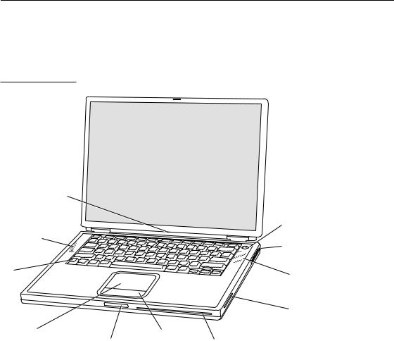
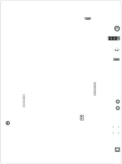
Figure 1-1 is a front view of the PowerBook G4 computer. Figure 1-2 is a back view showing the I/O ports.
Figure 1-1 Front view of the computer
Sleep indicator light
Built-in speaker/ microphone
Function key
Trackpad |
Display |
Trackpad |
|
release button |
button |
 Power button
 Security slot
Built-in speaker
AirPort antenna window
Slot-loading DVD-ROM /CD-RW Combo drive or DVD-R/CD-RW SuperDrive
Appearance |
15 |
Apple Computer, Inc. November 2002

C H A P T E R 1
Introduction
Figure 1-2 Back view showing I/O ports
|
|
|
AirPort antenna |
|
|
|
window |
Power |
|
|
PC Card |
adapter port |
Sleep indicator light |
eject button |
|
|
|
||
|
|
|
PC Card slot |
|
DVI-I port |
Internal |
Headphone |
|
modem port |
jack |
|
|
|
|
|
FireWire |
|
|
|
port |
|
|
|
Ethernet port |
USB ports |
|
Audio line-in connector |
(10/100/1000Base-T) |
|
|
TV out port |
|
|
|
|
Peripheral Devices
In addition to the devices that are included with the computer, several peripheral devices are available separately:
16Peripheral Devices
Apple Computer, Inc. November 2002

C H A P T E R 1
Introduction
■The PowerBook G4 Rechargeable Battery is available separately as an additional or replacement battery.
■The Apple Portable Power Adapter, which comes with the computer, is also available separately. The adapter can fully recharge a completely depleted battery in three hours or less while the computer is running, shut down, or in sleep mode.
■The Apple DVI to ADC Adapter, which enables the PowerBook G4 computer to support Apple’s ADC displays, is available separately.
■The Apple Pro Keyboard, a full-featured USB keyboard, is available separately.
■The Apple Pro Mouse, an optical USB mouse, is available separately.
■The AirPort Base Station is available separately.
■The AirPort Card is also available separately.
■A power cable for use on airliners is also available. The airline power cable should have a sense resistor of 24.3K ohms connected between the power plug's shell and ground. For more information, see “Power Controller” (page 30).
System Software
The PowerBook G4 computer comes with both Mac OS X version 10.2 and Mac OS 9.2.2 installed. Mac OS X is the default startup system. For the latest information, see the references listed in “Mac OS X” (page 81) and “Mac OS 9.2.2” (page 81).
Here are a few items of interest about the system software on the PowerBook G4 computer.
Open Firmware
System software on all current Macintosh models uses a design based on Open Firmware. With this approach, the ROM on the main logic board contains only the Open Firmware code needed to initialize the hardware and load an operating system. The rest of the system code is loaded into RAM from disk or from the network. For more information, see the references listed in “Open Firmware” (page 82).
System Software |
17 |
Apple Computer, Inc. November 2002

C H A P T E R 1
Introduction
Computer Identification
Rather than reading the box flag or the model string and then making assumptions about the computer’s features, applications that need to find out the features of the computer should use IORegistry calls to test for the features they require.
IORegistry calls are part of the I/O Kit API. For more information, see the references listed at “I/O Kit” (page 82).
Asset management software that reports the kind of computer it is running on can obtain the value of the model property from the IOService plane of the IORegistry. For the PowerBook G4 computer, the value of the model property is PowerBook3,5.
Power-Saving Features
The PowerBook G4 computer has several profiles to save power. These profiles are labeled on the Energy Saver panel of System Preferences.
Reduced Processor Speed
Reduced processor speed allows the software to change the processor’s clock speed, slowing down to conserve power or speeding up when more speed is needed. The slower clock speed is 667 MHz and the L3 cache is turned off.
■The system software uses a reduced processor speed to automatically conserve power under the following conditions:
■during system startup
■when battery charge is low
■when there is no battery installed
■when using airline power
■The user interface for the reduced processor speed is located in the options tab under the Energy Saver panel in System Preferences.
Operating Modes
The power management protocols on the PowerBook G4 computer support two power-saving modes: idle and sleep.
18System Software
Apple Computer, Inc. November 2002
C H A P T E R 1
Introduction
■Idle: The system is idling with the main processor stopped in a halted, low-power state. All clocks are running; the system can return to running code within a few nanoseconds. Cache coherency is maintained in this state.
■Sleep: The system is completely shut down, with only the DRAM state preserved for quick recovery. All processors are powered off with their state preserved in DRAM. All clocks in the system are suspended except for the 32.768 kHz timebase crystal on the PMU99 IC.
The computer automatically enters Idle mode after several seconds of inactivity. If the computer is attached to a network, it is able to respond to service requests and other events directed to the computer while it is in Idle mode.
While it is connected to an AC power supply, the computer can also respond to network activity when it is in sleep mode. The user can enable this feature by selecting Wake-on-LAN in the Energy Saver control panel.
When operating on the battery in sleep mode, the computer consumes less than 1 watt of power, meeting the Energy Star power-saving standard. When operating on the power adapter in sleep mode, the combined computer and adapter consume 3 to 4 watts of power.
Important
Peripherals such as PCMCIA cards and USB devices that do not conform to the computer’s power management protocols prevent the computer from switching to sleep mode and so deny the user the benefits of this energy-saving mode. When such peripherals are attached to the computer, the operating system displays a dialog to inform the user that the computer no longer meets the Energy Star requirements.
System Software |
19 |
Apple Computer, Inc. November 2002
C H A P T E R 1
Introduction
20System Software
Apple Computer, Inc. November 2002
C H A P T E R 2
Architecture
This chapter describes the architecture of the PowerBook G4 computer. It includes information about the major components on the main logic board: the microprocessor, the other main ICs, and the buses that connect them to each other and to the I/O interfaces.
Block Diagram and Buses
This section is an overview of the major ICs and buses on the computer’s main logic board.
Block Diagram
Figure 2-1 is a simplified block diagram of the main logic board. The diagram shows the input and output connectors, the main ICs, and the buses that connect them together.
Block Diagram and Buses |
21 |
Apple Computer, Inc. November 2002 |
|
C H A P T |
E R 2 |
|
Architecture |
|
|
Figure 2-1 |
Block diagram |
|
|
|
|
|
|
|
|
|
|
|
|
|
|
|
PowerPC G4 |
|
|
|
|
|
|
|
|
|
|
|
|
|
|
|
|
|
|
|
||||
|
|
|
|
|
|
L3 |
|
|
|
|
|
|
|
|
|
|
|
|
|
|
|
|
|
|
|
|
|
|||||||
|
|
|
|
|
|
|
|
microprocessor |
|
|
|
|
|
Connector to |
|
|||||||||||||||||||
|
|
|
|
|
|
cache |
|
|
|
|
|
|
|
|
||||||||||||||||||||
|
SO-DIMM |
|
|
L2 cache: 256K |
|
|
|
|
|
|
||||||||||||||||||||||||
|
|
|
|
|
|
|
|
|
|
internal display |
|
|||||||||||||||||||||||
|
|
|
|
|
|
|
|
|
|
|
|
|
|
|
|
|||||||||||||||||||
|
|
|
slots |
memory bus |
Max bus |
|
|
|
AGP |
|
|
|
|
|
|
|
|
|
|
|
|
|
|
|
|
|||||||||
|
|
|
|
|
|
|
|
|
|
|
|
|
|
|
|
|
|
|
|
|
|
|
||||||||||||
|
|
|
|
|
|
|
|
|
|
|
|
|
|
|
|
|
|
|
|
|
|
|
||||||||||||
|
|
|
|
|
|
|
|
|
|
|
|
|
|
|
|
|
|
|
|
|
|
|
|
|
||||||||||
|
|
|
|
|
|
|
|
|
|
|
|
|
Mobility |
|
|
|
|
|
|
|||||||||||||||
|
|
|
|
|
|
|
|
|
bus |
|
|
|
|
|
|
|
|
|
|
|||||||||||||||
|
|
|
|
|
|
|
|
|
|
|
|
|
|
|
|
|
|
|
|
|
Radeon 9000 |
|
|
|
|
|
||||||||
|
|
|
|
|
|
|
|
|
|
|
|
Uni-N |
|
|
|
|
|
|
|
graphics IC |
|
|
|
|
|
|
||||||||
|
|
|
|
|
|
|
|
|
|
|
|
|
|
|
|
|
|
|
|
|
|
|
|
|
|
|
|
|
|
|
|
|
||
|
|
|
|
|
|
|
|
|
|
|
|
memory |
|
|
|
|
|
|
|
|
|
|
|
|
|
|
|
|
|
|
|
|
|
|
|
|
|
|
|
|
|
|
|
|
|
|
controller |
|
|
|
|
|
|
|
|
|
|
|
|
|
|
|
|
|
|
|
|
|
|
|
CardBus slot |
|
|
|
|
|
|
|
|
|
|
|
|
|
Ethernet |
|
|
|
|
|
||||||||||||||
|
|
and PCI |
|
|
|
|
|
|
|
|
|
|
|
|
PHY |
|
|
|
|
|
||||||||||||||
|
|
|
|
|
|
|
|
|
|
|
|
|
|
|
|
|
|
|||||||||||||||||
|
|
connector |
|
bus bridge |
|
|
|
|
|
|
|
|
|
|
|
|
|
|
|
|
|
|||||||||||||
|
|
|
|
|
|
|
|
|
|
|
|
|
|
|
|
|
|
|
|
|
|
|
|
|||||||||||
|
|
|
|
|
|
|
|
|
|
|
|
|
|
|
|
|
|
|
|
|
|
|
|
|
|
|
|
|
|
|
|
|
|
|
|
|
|
|
|
|
|
|
|
|
|
|
|
|
|
|
|
|
|
|
|
|
|
|
|
|
FireWire |
|
|
|
|
|
|||
|
|
|
|
|
|
|
|
|
|
|
|
|
|
|
|
|
|
|
|
|
|
|
|
|
|
|
|
|
|
|
||||
|
|
|
|
|
|
|
|
|
|
|
|
|
|
|
|
|
|
|
|
|
|
|
|
|
|
PHY |
|
|
|
|
|
|||
|
|
|
|
|
CardBus |
|
|
|
|
|
|
|
|
|
|
|
|
|
|
|
|
|
|
|
|
|
|
|||||||
|
|
|
|
|
|
|
|
|
|
|
|
|
|
|
|
|
|
|
|
|
|
|
|
|
|
|
|
|
|
|
||||
|
|
|
|
|
|
bridge |
|
|
|
|
|
|
|
|
|
|
|
|
|
|
|
|
|
|
|
|
|
|
|
|
|
|
||
|
|
|
|
|
|
|
|
|
|
|
|
|
|
|
|
|
Boot |
|
|
|
|
|
|
|
|
|
|
|
|
|
|
|
|
|
|
|
|
|
|
|
|
|
|
|
|
|
|
|
|
|
|
|
|
|
|
|
|
|
|
|
|
|
|
|
|
|
|
||
|
|
|
|
|
|
|
|
|
|
|
PCI bus |
|
|
|
ROM |
|
|
|
|
|
|
|
|
|
|
|
|
|
|
|
|
|||
Connector to internal |
|
|
|
|
|
|
|
|
|
|
|
|
Connector to |
|
||||||||||||||||||||
|
|
|
|
|
|
|
|
|
|
|
|
|
|
|
|
|||||||||||||||||||
|
|
|
|
Ultra-ATA bus |
|
|
|
|||||||||||||||||||||||||||
|
|
|
|
|
|
|
|
|
||||||||||||||||||||||||||
DVD-ROM/CD-RW Combo |
|
|
|
|
|
|
|
internal IDE |
|
|||||||||||||||||||||||||
|
|
|
|
|
|
|
|
|
|
|
|
|
|
|
|
|||||||||||||||||||
drive or DVD-R/CD-RW |
|
|
|
|
|
|
|
|
|
|
|
|
|
|
|
|
|
disk drive |
|
|||||||||||||||
SuperDrive |
|
|
|
|
|
|
|
|
|
|
|
|
|
|
|
|
|
|
|
|
|
|
|
|
|
|
|
|
||||||
|
|
|
|
|
|
ATA bus |
|
|
|
|
|
|
|
|
|
|
|
|
|
|
|
|
|
|
|
|
|
|||||||
|
|
|
|
|
|
|
|
|
|
|
|
|
|
|
|
|
|
|
Snapper |
|
|
|
|
|
|
|
|
|
||||||
|
|
|
|
|
|
|
|
|
|
|
|
|
|
|
|
|
|
|
|
|
audio |
|
|
|
|
|
|
|
|
|
||||
Connector |
|
|
|
|
|
|
|
|
|
|
|
|
|
|
|
|
|
|
|
|
|
|
|
|||||||||||
|
|
|
|
|
|
|
|
|
|
|
|
|
|
|
|
|
|
|
|
|
|
|
|
|
|
|
||||||||
|
|
|
|
|
|
|
|
|
|
|
|
|
|
|
|
|
Internal |
|
||||||||||||||||
to internal |
|
|
|
|
|
|
|
|
KeyLargo |
|
|
|
|
|
|
|
|
|
|
|||||||||||||||
antenna |
|
|
|
|
|
|
|
|
I/O device |
|
|
|
|
|
|
|
|
|
speaker |
|
||||||||||||||
|
|
|
|
|
|
|
|
|
|
|
|
and disk |
|
|
|
|
|
|
|
|
|
connector |
|
|||||||||||
|
|
|
|
|
|
|
|
|
|
|
|
controller |
|
|
|
|
|
|
|
|
|
|
|
|
|
|
|
|
|
|
|
|
||
|
RF |
|
|
|
|
|
|
|
|
|
|
|
|
|
|
|
|
|
|
|
|
|
|
|
|
|
|
|
|
|
|
|
|
|
|
DSP and |
|
|
|
|
|
|
|
|
|
|
|
|
|
|
|
|
|
|
|
|
|
|
|
|
|||||||||
|
and |
|
|
|
|
|
|
|
|
|
|
|
|
|
|
|
|
|
|
|
|
|
|
|
|
|
|
|||||||
|
|
|
|
MAC |
|
|
|
|
|
|
|
|
|
|
|
|
|
|
|
|
|
|
|
|
|
|
|
|
||||||
|
IF |
|
|
|
|
|
|
|
|
|
|
|
|
|
|
|
|
|
|
|
|
|
|
|
|
|
|
|
||||||
|
|
|
|
|
|
|
|
|
|
|
|
|
|
|
|
|
|
|
|
|
|
|
|
|
|
|
|
|
|
|
|
|
||
|
|
|
|
|
|
|
|
|
|
|
|
|
|
|
|
|
|
|
|
|
|
|
|
|
|
|
|
|
|
|
|
|
|
|
|
Wireless LAN module |
|
|
|
|
|
USB |
|
|
|
|
|
|
|
|
|
|
|
|
|
|
|
|
|||||||||||
|
|
|
|
|
|
|
|
|
|
|
|
|
|
|
|
|
|
|
|
|
|
|
Data pump |
|
|
|
|
|||||||
|
|
|
|
PMU99 |
|
|
|
|
|
|
|
|
|
|
|
|
|
|
|
|
|
|
and DAA |
|
|
|
|
|||||||
|
|
|
|
power |
|
|
|
|
|
|
|
|
|
|
|
|
|
|
|
|
|
|
|
|
|
|
|
|
|
|
|
|||
|
|
|
|
|
|
|
|
|
|
|
|
|
|
|
|
|
|
|
|
|
Modem module |
|
||||||||||||
|
|
|
|
controller |
|
|
|
|
|
|
|
|
|
|
|
|
|
|
|
|
|
|
||||||||||||
|
|
|
|
|
|
|
|
|
|
|
|
|
|
|
|
|
|
|
|
|
|
|||||||||||||
|
|
|
|
|
|
|
|
|
|
|
|
|
|
|
|
|
|
|
|
|
|
|
|
|
|
|
|
|
|
|
|
|
|
|
S-video connector
DVI-I monitor connector
Ethernet port
FireWire port
Audio input jack
Headphone jack
USB port
USB port
Telephone connector
22Block Diagram and Buses
Apple Computer, Inc. November 2002

C H A P T E R 2
Architecture
Main ICs and Buses
The architecture of the PowerBook G4 computer is designed around the PowerPC G4 microprocessor and two custom ICs: the Uni-N memory controller and bus bridge, and the KeyLargo I/O device controller. Those three ICs occupy the center of the block diagram.
The PowerPC G4 microprocessor is connected to the Uni-N memory controller and bus bridge IC by a MaxBus bus. The bus clock speed is 133 MHz. The Uni-N IC has other buses that connect with the KeyLargo IC, the main system RAM, and the graphics IC. The buses implemented by the Uni-N IC are summarized in Table 2-1, which is in the section “Memory Controller and Bus Bridge” (page 24).
The Uni-N IC is connected to the KeyLargo I/O controller IC by a 32-bit PCI bus with a bus clock speed of 33 MHz. That bus also connects to the Boot ROM and the CardBus controller. The KeyLargo IC has other buses that connect with the hard disk drive and the optical drive, the power controller IC, the sound IC, the internal modem module, and the wireless LAN module.
Each of the components listed here is described in one of the following sections.
Microprocessor and Caches
The microprocessor communicates with the rest of the system by way of a 64-bit MaxBus bus to the Uni-N IC. The microprocessor has a separate bus to its internal second-level cache.
PowerPC G4 Microprocessor
The PowerPC G4 microprocessor used in the PowerBook G4 computer has many powerful features, including an efficient pipelined system bus called MaxBus.
Features of the PowerPC G4 include
■32-bit PowerPC implementation
■superscalar PowerPC core
Microprocessor and Caches |
23 |
Apple Computer, Inc. November 2002

C H A P T E R 2
Architecture
■Velocity Engine (AltiVec technology): 128-bit-wide vector execution unit
■dual 32 KB instruction and data caches
■an on-chip level 2 (L2) cache consisting of 256 KB with a clock speed ratio of 1:1
■high bandwidth MaxBus (also compatible with 60x bus)
■fully symmetric multiprocessing capability
The PowerPC G4 microprocessor in the PowerBook G4 computer runs at a clock speed of 867 MHz or 1 GHz.
Level 2 Cache
The data storage for the L2 cache consists of 256 KB of fast static RAM that is built into the microprocessor chip along with the cache controller and tag storage. The built-in L2 cache runs at the same clock speed as the microprocessor.
Level 3 Cache
The data storage for the L3 cache is 1 MB of DDR SRAM running at a clock speed ratio of 5:1. The tag storage for the L3 cache is built into the microprocessor.
Memory Controller and Bus Bridge
The Uni-N memory controller and bus bridge IC provides cost and performance benefits by combining several functions into a single IC. It contains the memory controller, the PCI bus bridge, the Ethernet and FireWire interfaces, and the AGP interface.
Each of the separate communication channels in the Uni-N IC can operate at its full capacity without degrading the performance of the other channels.
24Memory Controller and Bus Bridge
Apple Computer, Inc. November 2002

C H A P T E R 2
Architecture
In addition to the four buses listed in Table 2-1, the Uni-N IC also has separate interfaces to the physical layer (PHY) ICs for Ethernet and FireWire, and an IIC (inter-IC control bus) interface that is used for configuring the memory subsystem.
|
Table 2-1 |
Buses supported by the Uni-N IC |
|
||
|
Bus |
|
Destinations |
Width of data path |
Bus clock speed |
|
|
|
|
||
|
MaxBus |
Microprocessor 64 bits |
133 MHz |
||
|
|
|
|
|
|
|
Memory |
System RAM |
64 bits |
133 MHz |
|
|
|
|
|
|
|
|
PCI |
KeyLargo IC |
32 bits |
33 MHz |
|
|
|
|
and Boot ROM |
|
|
|
|
|
|
|
|
|
AGP |
Graphics IC |
32 bits |
133 MHz |
|
|
|
|
|
|
|
The microprocessor and the I/O controller IC are described in their own sections. The following sections describe the other subsystems that are connected to the Uni-N IC.
System RAM
The memory subsystem in the PowerBook G4 computer supports two slots for 144-pin SO-DIMMs (small-outline dual inline memory modules). The data bus to the RAM and DIMM is 64 bits wide, and the memory interface is synchronized to the MaxBus bus interface at 133 MHz. See “RAM Expansion Slots” (page 71).
Boot ROM
The boot ROM is connected to the Uni-N IC by way of the high byte of the PCI bus plus three additional control signals: chip select, write enable, and output enable. The boot ROM is a 1 MB by 8 bit device.
Memory Controller and Bus Bridge |
25 |
Apple Computer, Inc. November 2002

C H A P T E R 2
Architecture
FireWire Controller
The Uni-N IC includes an IEEE 1394a FireWire controller with a maximum data rate of 400 Mbits (50 MB) per second. The Uni-N IC provides DMA (direct memory access) support for the FireWire interface.
The controller in the Uni-N IC implements the FireWire link layer. A physical layer IC, called a PHY, implements the electrical signaling protocol of the FireWire interface and provides the electrical signals to the port. For more information, see “FireWire Connector” (page 35).
Ethernet Controller
The Uni-N IC includes an Ethernet media access controller (MAC) that implements the link layer. The Uni-N IC provides DB-DMA support for the Ethernet interface.
The Ethernet controller in the Uni-N IC is connected to a PHY interface IC that provides the electrical signals to the port. The PHY is capable of operating in either 10Base-T, 100Base-T, or 1000Base-T mode: The actual speed of the link is automatically negotiated by the PHY and the bridge or router to which it is connected. For more information, see “Ethernet Port” (page 38).
The PHY supports Auto-MDIX, which allows the use of straight-through cables in crossover situations (and conversely). For more information, see “Ethernet Port” (page 38).
Video Display Subsystem
The video display subsystem contains the graphics controller IC along with either 32 MB of DDR memory in the 867 MHz computer or 64 MB of DDR memory (32 MB internal and another 32 MB external to the IC) in the 1 GHz computer. The graphics IC, an ATI Mobility Radeon 9000, contains 2D and 3D acceleration engines, front-end and back-end scalers, a CRT controller, and an AGP4x bus interface with bus master capability.
The features of the Mobility Radeon 9000 include
■graphics processor clock speed of 200 MHz
■memory clock speed of 200 MHz
■support for 32 MB of DDR video memory with 64-bit interface
26Memory Controller and Bus Bridge
Apple Computer, Inc. November 2002
C H A P T E R 2
Architecture
■support for 64 MB of DDR video memory with 128-bit interface
■2D and 3D graphics acceleration
■transform acceleration
■lighting acceleration
■video acceleration
■support for MPEG decoding
■support for video mirror mode
■support for dual-display mode
■S-video output for a TV monitor
■support for programmable pixel and vertex shading
The interface between the graphics IC and the rest of the system is an AGP4x (accelerated graphics port, quadruple speed) bus on the Uni-N IC. To give the graphics IC fast access to system memory, the AGP bus has separate address and data lines and supports deeply pipelined read and write operations. The AGP bus has 32 data lines and a clock speed of 133 MHz.
The graphics IC uses a graphics address remapping table (GART) to translate AGP logical addresses into physical addresses. The graphics driver software can allocate memory in both the graphics SDRAM and the main memory.
The graphics IC supports the built-in flat-panel display and an external monitor. The external monitor can either mirror the built-in display or show additional desktop space (dual-display mode). For information about the displays and supported resolutions, see “Flat-Panel Display” (page 59) and “External Monitors” (page 60).
Memory Controller and Bus Bridge |
27 |
Apple Computer, Inc. November 2002

C H A P T E R 2
Architecture
I/O Controller
The I/O controller IC in the PowerBook G4 computer is a custom IC called KeyLargo. It provides the interface and control signals for the devices and functions described in the following sections.
Note: In the device tree, the I/O controller is named “mac-io”.
DMA Support
The KeyLargo IC provides DB-DMA (descriptor-based direct memory access) support for the following I/O channels:
■Ultra DMA ATA interface to the the internal hard drive
■modem slot interface to the built-in modem
■IIS channel to the sound IC
The DB-DMA system provides a scatter-gather process based on memory resident data structures that describe the data transfers. The DMA engine is enhanced to allow bursting of data files for improved performance.
Interrupt Support
The KeyLargo IC has an interrupt controller (MPIC) that handles interrupts generated within the IC as well as external interrupts, such as those from the Ethernet and FireWire controllers.
USB Interface
The KeyLargo IC implements two independent USB controllers (root hubs), each of which is connected to one of the ports on the back panel of the computer. The use of two independent controllers allows both USB ports to support high data rate
28I/O Controller
Apple Computer, Inc. November 2002

C H A P T E R 2
Architecture
devices at the same time with no degradation of their performance. If a user connects a high-speed (12 Mbps) device to one port and another high-speed device to the other, both devices can operate at their full data rates.
The two external USB connectors support USB devices with data transfer rates of 1.5 Mbps or 12 Mbps. For more information about the connectors, see “USB Connectors” (page 33).
USB devices connected to the PowerBook G4 computer are required to support USB-suspend mode as defined in the USB specification. Information about the operation of USB-suspend mode on Macintosh computers is included in the Mac OS USB DDK API Reference. To obtain it, see the reference at “USB Interface” (page 84).
The USB ports on the PowerBook G4 computer comply with the Universal Serial Bus Specification 1.1 Final Draft Revision. The USB controllers comply with the Open Host Controller Interface (OHCI) specification.
Ultra DMA/66 Interface
The KeyLargo IC provides an Ultra DMA/66 channel that is connected to the internal hard disk drive. The KeyLargo IC provides DB-DMA (descriptor-based direct memory access) support for the Ultra DMA interface.
The internal hard disk drive is connected as device 0 (master) in an ATA Device 0/ 1 configuration.
EIDE Interface
The KeyLargo IC provides an EIDE interface (ATA bus) that supports the Combo (DVD-ROM/CD-RW) drive, SuperDrive (DVD-R/CD-RW) drive, and the wireless LAN module. The Combo and SuperDrive drives are ATAPI drives and are device-selected as master in an ATA device configuration.
Modem Support
The internal modem is connected to an internal USB port. The KeyLargo IC provides DB-DMA support for the modem interface. The modem provides digital call progress signals to the Snapper sound circuitry.
I/O Controller |
29 |
Apple Computer, Inc. November 2002
 Loading...