


 Loading...
K Service Source
Apple AudioVision 14
Display

K Service Source
Basics
Apple AudioVision 14 Display

Basics |
Self-Threading Screws - 1 |
|
|
|
|
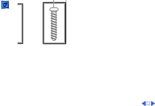
Self-Threading Screws
Caution: Improperly installed self-threading screws could damage the AudioVision 14 Display. Thread the screws properly and do not overtighten them.
The AudioVision 14 Display uses both machine screws and self-threading screws. Be aware of the following guidelines when you are replacing a self-threading screw:
• Never overtighten self-threading screws.
• Before tightening a self-threading screw, back the screw off slightly to be sure it is threaded properly.
Basics |
Self-Threading Screws - 2 |
|||
|
|
|
||
Machine Screw |
Self-Threading Screw |
|||
|
|
|
|
|
|
|
|
|
|

K Service Source
Specifications
Apple AudioVision 14 Display

Specifications |
Characteristics - 1 |
|
|
|
|
Characteristics
Picture Tube
14-inch diagonal, 13-inch viewable screen Trinitron CRT
.26-mm pitch aperture grille
Screen Resolution
Scan Rates
Active Video
Display Area
640x480
Horizontal scan rate: 35.0 kHz Vertical refresh rate: 66.7 Hz
9.3 in. by 6.9 in.
(235 mm by 176 mm)

|
Specifications |
Characteristics - 2 |
|
|
|
|
|
Video Input Signals |
Red, green, and blue video signals;.714 V peak to peak; white |
||
|
|
positive |
|
|
|
Composite synchronization, negative-going TTL |
|
Audio Input Signals
Microphone
Speakers
Accepts audio signal of up to 6 Vpp (line level—low sensitivity) or as low as 20 mVpp (microphone level—high sensitivity) without clipping the signal, depending upon the level and sensitivity setting
Directional, optimized for use in speech recognition and other voice-related applications
Stereo, with ported (base reflex) chamber design Minimum loudness: 90 dB SPL at 1 kHz at 0.5 m Frequency response: 100 Hz–15 kHz ± 3dB

|
Specifications |
Characteristics - 3 |
|||
|
|
|
|
||
Headphone Jack |
Output level: 1.75 Vpp into 4 ohm load and 2 Vpp into 10 k ohm |
||||
|
|
load |
|||
|
|
|
|
|
|
|
|
|
|
|
|

Specifications |
Controls - 4 |
|
|
|
|
Controls
User Controls
Front Keypad: Contrast, brightness, and volume keys; mute button; microphone button
Back panel: On/off switch

Specifications |
Electrical - 5 |
|
|
|
|
Voltage
Frequency
Power
Electrical
100–240 VAC ± 10%
50–60 Hz ± 3%
55 W maximum, all line conditions
The monitor contains internal power-line fuse protection. This fuse should be replaced with the same type by a qualified
service technician.
|
Specifications |
Physical - 6 |
|
|
|
|
|
|
|
Physical |
|
Size |
Height: 13 in. (330 mm) |
||
|
|
Width: 13.5 in. (344 mm) |
|
|
|
Depth: 15.5 in. (394 mm) |
|
Weight
Warm-Up Time
33 lb. (15 kg)
20 minutes required to meet all specifications

Specifications |
Environmental - 7 |
|
|
|
|
Environmental
Operating
Temperature
Relative Humidity
50–104°F (10–40°C)
90% maximum, noncondensing

K Service Source
Troubleshooting
Apple AudioVision 14 Display

Troubleshooting |
General - 1 |
|
|
General
The Symptom Charts included in this chapter will help you diagnose specific symptoms related to your product. Because cures are listed on the charts in the order of most likely solution, try the first cure first. Verify whether or not the product continues to exhibit the symptom. If the symptom persists, try the next cure. (Note: If you have replaced a module, reinstall the original module before you proceed to the next cure.)
If you are not sure what the problem is, or if the Symptom Charts do not resolve the problem, refer to the Flowchart for the product family.
For additional assistance, contact Apple Technical Support.

 Troubleshooting Symptom Charts/No Raster - 2
Symptom Charts
No Raster
No raster, LED off |
1 |
Ensure monitor’s video cable is connected to the computer or |
||
|
|
the video card in the computer. |
||
|
2 |
Check power cable connections and power switch. |
||
|
3 |
Check all connections on main board. |
||
|
4 |
Replace blown fuse. |
||
|
5 |
Replace main board. |
||
No raster, LED on, |
1 |
Ensure monitor’s video cable is connected to the computer or |
||
CRT filament on |
|
the video card in the computer. |
||
|
2 |
Adjust contrast and brightness knobs. |
||
|
3 |
Connect known-good monitor and verify that built-in video |
||
|
|
signal or video card is working properly. |
||
|
4 |
Check all connections on main board. Make sure video |
||
|
|
connector is secure and wires are inside plastic connector. |
||
|
5 |
Perform video adjustments. Refer to “Video” in Adjustments |
||
|
|
chapter. |
||
|
6 |
Replace main board. |
||
|
7 |
Replace CRT. |
||
|
|
|
|
|
|
|
|
|
|

 Troubleshooting Symptom Charts/Geometry - 3
Geometry
Raster too short, tall, |
1 |
Adjust vertical or horizontal size controls. Refer to |
narrow, or wide |
|
“Geometry” in Adjustments chapter. |
|
2 |
Replace main board. |
Raster not centered |
1 |
Move unit away from monitors, fluorescent lights, or other |
|
|
electrical equipment. |
|
2 |
Adjust vertical or horizontal center controls. Refer to |
|
|
“Geometry” in Adjustments chapter. |
|
3 |
Replace main board. |
Horizontal linearity |
Replace main board. |
|
bad (size of text |
|
|
differs at sides of |
|
|
screen) |
|
|

|
|
Troubleshooting |
|
Symptom Charts/Geometry (Continued) - 4 |
|
|
|
|
|
|
|
|
|
|
Geometry (Continued) |
||
|
|
|
|||
Vertical linearity bad |
Replace main board. |
||||
(size of text differs at |
|
|
|
||
top vs. bottom of |
|
|
|
||
screen) |
|
|
|
||
Abnormal or |
1 |
Move unit away from monitors, fluorescent lights, or other |
|||
distorted raster |
|
electrical equipment. |
|||
|
|
|
2 |
Perform geometry adjustments. Refer to “Geometry” in |
|
|
|
|
|
Adjustments chapter. |
|
|
|
|
3 |
Replace main board. |
|
|
|
|
4 |
Replace CRT (rarely required). |
|

|
Troubleshooting |
|
Symptom Charts/Geometry (Continued) - 5 |
||
|
|
|
|||
|
|
Geometry (Continued) |
|||
Entire raster is tilted |
1 |
Move unit away from monitors, fluorescent lights, or other |
|||
|
|
|
electrical equipment. |
||
|
|
2 |
Perform geometry adjustments. Refer to “Geometry” in |
||
|
|
|
Adjustments chapter. |
||
|
|
3 |
Perform geometric distortion adjustments. Refer to |
||
|
|
|
“Geometric Distortion” in Adjustments chapter. |
||
|
|
4 |
Replace main board. |
||
|
|
|
|
|
|
|
|
|
|
|
|

 Troubleshooting Symptom Charts/Synchronization - 6
Synchronization
Picture breaks into |
1 |
Connect known-good monitor and verify that built-in video |
diagonal lines |
|
signal or video card is working properly. |
|
2 |
Replace main board. |
Picture rolls |
1 |
Connect known-good monitor and verify that built-in video |
vertically |
|
signal or video card is working properly. |
|
2 |
Replace main board. |
Picture breaks and |
1 |
Connect known-good monitor and verify that built-in video |
rolls horizontally |
|
signal or video card is working properly. |
|
2 |
Replace main board. |

 Troubleshooting Symptom Charts/Synchronization (Continued) - 7
|
Synchronization |
(Continued) |
|
|
Black raster with |
1 |
Replace main board. |
|
|
single vertical or |
2 |
Replace CRT. |
|
|
horizontal line |
|
|
|
|
|
|
|
|
|
|
|
|
|
|
 Troubleshooting Symptom Charts/Video - 8
Video
Raster too dark, too |
1 |
Adjust external contrast and brightness controls. |
bright, or washed out |
2 |
Connect known-good monitor and verify that built-in video |
|
|
signal or video card is working properly. |
|
3 |
Perform video adjustments. Refer to “Video” in Adjustments |
|
|
chapter. |
|
4 |
Replace main board. |
|
5 |
Replace CRT (rarely required). |
Out of focus |
1 |
Perform focus adjustment. Refer to “Video” in Adjustments |
|
|
chapter. |
|
2 |
Replace main board. |
|
3 |
Adjust focus controls to their limits. If bad focus remains on |
|
|
one part of display, replace CRT. |

|
Troubleshooting |
|
Symptom Charts/Video (Continued) - 9 |
||
|
|
|
|||
|
|
Video (Continued) |
|||
Predominant color |
1 |
Check video card in computer. |
|||
tint |
2 |
Perform video adjustments. Refer to “Video” in Adjustments |
|||
|
|
|
chapter. |
||
|
|
3 |
Replace main board. |
||
|
|
4 |
Replace CRT (if you cannot eliminate red, green, or blue |
||
|
|
|
tint). |
||
Out of convergence |
1 |
Connect known-good monitor and verify that built-in video |
|||
(color bleeding out |
|
signal or video card is working properly. |
|||
from text or lines) |
2 |
Perform convergence adjustments. Refer to “Video” in |
|||
|
|
|
Adjustments chapter. |
||
|
|
3 |
Replace main board. |
||
|
|
4 |
Replace CRT. |
||
|
|
|
|
|
|
|
|
|
|
|
|

 Troubleshooting Symptom Charts/Audio - 10
Audio
Sound comes out of |
One of sound output options may be set to Stereo when your |
|||
only one speaker |
computer is only capable of Mono sound output. |
|||
Internal microphone |
1 |
To turn on microphone, press microphone button on keypad. |
||
doesn’t record |
|
Microphone-on LED lights up when microphone is on. |
||
|
2 |
Make sure that monitor is selected as sound input and |
||
|
|
playback source. |
||
No sound or volume is |
1 |
Verify that external sound sources are securely connected to |
||
too low |
|
monitor’s sound-out port. |
||
|
2 |
Press volume key on keypad. |
||
|
3 |
Press mute button to turn mute off. |
||
|
4 |
Press microphone button to turn microphone off. |
||
|
|
|
|
|
|
|
|
|
|

 Troubleshooting Symptom Charts/Miscellaneous - 11
Miscellaneous
Picture jitters or |
1 |
Move unit away from monitors, fluorescent lights, or other |
flashes |
|
electrical equipment. |
|
2 |
Check that all ground cables are secure. |
|
3 |
Replace main board. |
Intermittently shuts |
Replace main board. |
|
down |
|
|
Flashing or wavy |
Replace main board. |
|
screen |
|
|
Black screen spots |
Replace CRT. |
|
(burnt phosphor) |
|
|

 Troubleshooting Symptom Charts/Miscellaneous (Continued) - 12
|
Miscellaneous |
(Continued) |
Monitor emits high- |
Replace main board. |
|
pitched noise |
|
|
Does not degauss |
Replace main board. |
|
Erratic or no |
Replace keyboard cable, keyboard, mouse, or other ADB device. |
|
communication with |
|
|
ADB device |
|
|
Moving and clicking a |
Some models of Logitech mice are incompatible with this display. |
|
Logitech mouse has no |
Refer customers to Logitech for information on mouse |
|
effect on screen, but |
compatibility and upgrades. The display is not at fault; do not |
|
keyboard input is |
replace it. |
|
accepted |
|
|

 Troubleshooting Symptom Charts/Miscellaneous (Continued) - 13
|
Miscellaneous (Continued) |
||
Thin horizontal line |
Displays smaller than 15 inches with tron-style CRTs typically |
||
on screen |
have a single horizontal grid wire about one-third of the way from |
||
|
the bottom of the display image. This supporting wire, which is |
||
|
thinner than a human hair, stabilizes the aperture grill against |
||
|
shocks. The line is common to all tron-style displays and is not a |
||
|
screen defect. It cannot be adjusted out or eliminated by repairing |
||
|
or replacing display modules. |
||
|
|
|
|
|
|
|
|

K Service Source
Take Apart
Apple AudioVision 14 Display
Take Apart |
Rear Cover - 1 |
|
|
|
|
Rear Cover
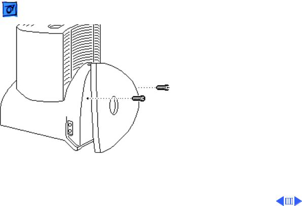
Rear Cover
No preliminary steps are r equired before you begin this procedure.
1With the monitor facedown on a protective pad, swivel the monitor stand to access the two rear cover screws.
2Using a T-15 torx driver, remove the screws.
Take Apart |
|
Rear Cover - 2 |
|
|
|
|
|
|
Rear Cover |
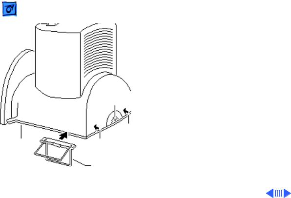
3 Move the monitor so |
|
|
that the microphone is |
||
|
|
||
|
|
toward you. |
|
|
|
4 Note: The locking tabs |
|
|
|
are located 1.5 inches in |
|
|
|
from the sides of the |
|
|
|
rear cover. |
|
|
|
Press down on the |
|
|
|
locking tabs. Using the |
|
|
|
pull-apart tool, pry |
|
|
Microphone |
apart the sides of the |
|
|
rear cover. |
||
|
|
||
|
Locking Tab |
|
|
Bezel |
Locking Tab |
|
|
|
Pull-Apart Tool |
|
|

 Take Apart
Rear
Cover
Rear Cover - 3
5 Lift off the rear cover.
Replacement Note: Line up the rear cover
Groove grooves with the base assembly guides and slide on the rear cover.
Guide
Loading...