


 Loading...
User Guide
WARNING
To prevent fire or shock hazard, do not expose this appliance to rain or moisture.
Important Notice
The material in this document is copyright to AKAI professional M.I. Corp., and may not be quoted or reproduced in any form without written permission from the company.
LIMITED SOFTWARE WARRANTY POLICY
All the software provided with, or purchased especially for, AKAI professional products has been tested for functionality. AKAI professional M.I. Corp. will make its best efforts to correct reported software defects for future releases subject to technical practicabilities.
AKAI professional M.I. Corp. makes no warranty or representation either expressed or implied with respect to the system's performance or fitness for a particular purpose.
In no event will AKAI professional M.I. Corp. be liable for direct or indirect damages arising from any defect in the software or its documentation. Further, AKAI professional M.I. Corp. will not accept any liability for any programs, sounds, audio recording or sequences stored in or used with AKAI professional products, including the cost of recovery of such data.
The warranties, remedies and disclaimers above are exclusive and take precedence over all others, oral or written, express or implied, to the extent permitted by law in the geographical area of the product's use. No employee of AKAI professional M.I. Corp., agent, distributor or employee of an agent or distributor is authorised to offer any variation from this policy.
WARNING!!
To prevent fire or shock hazard, do not expose this appliance to rain or moisture.
1-En
CAUTION
RISK OF ELECTRIC SHOCK
DO NOT OPEN
CAUTION: TO REDUCE THE RISK OF ELECTRIC SHOCK
DO NOT REMOVE COVER (OR BACK).
NO USER-SERVICEABLE PARTS INSIDE.
REFER SERVICING TO QUALIFIED SERVICE PERSONNEL.
THE SYMBOLS ARE RULED BY UL STANDARDS (U.S.A.)
The lightning flash with arrowhead symbol, within an equilateral triangle, is intended to alert the user to the presence of uninsulated “dangerous voltage” within the product’s enclosure; that may be of sufficient magnitude to constitute a risk of electric shock to persons.
The exclamation point within an equilateral triangle is intented to alert the user to the presence of important operating and maintenance (servicing) instructions in the literature accompanying the appliance.
5B-En
Lithium battery
This product uses a lithium battery for memory backup.
The lithium battery should only be replaced by qualified service personnel. Improper handling may cause risk of explosion.
24A-En
3/5/2002
WARNING: WHEN USING ELECTRIC PRODUCTS, BASIC PRECAUTIONS SHOULD ALWAYS BE FOLLOWED, INCLUDING THE FOLLOWING:
WARNING
The Z4/Z8 is designed to be used in a standard household environment.
Power requirements for electrical equipment vary from area to area. Please ensure that your Z4/Z8 meets the power requirements in your area. If in doubt, consult a qualified electrician or AKAI professional dealer.
120 VAC |
@ 60 Hz for USA and Canada |
220~240 VAC |
@ 50 Hz for Europe |
240 VAC |
@ 50 Hz for Australia |
PROTECTING YOURSELF AND THE Z4/Z8
•Never touch the AC plug with wet hands.
•Always disconnect the Z4/Z8 from the power supply by pulling on the plug, not the cord.
•Allow only an AKAI professional dealer or qualified professional engineer to repair or reassemble the Z4/Z8. Apart from voiding the warranty, unauthorized engineers might touch live internal parts and receive a serious electrical shock. There are no user serviceable parts inside.
•Do not put, or allow anyone to put any object, especially metal objects, into the Z4/Z8.
•Use only a household AC power supply. Never use a DC power supply.
•If water or any other liquid is spilled into or onto the Z4/Z8, disconnect the power, and call your dealer.
•Make sure that the unit is well-ventilated, and away from direct sunlight.
•To avoid damage to internal circuitry, as well as the external finish, keep the Z4/Z8 away from sources of direct heat (stoves, radiators, etc.).
•Avoid using aerosol insecticides, etc. near the Z4/Z8. They may damage the surface, and may ignite.
•Do not use denatured alcohol, thinner or similar chemicals to clean the Z4/Z8. They will damage the finish.
•Modification of this equipment is dangerous, and can result in the functions of the Z4/Z8 being impaired. Never attempt to modify the equipment in any way.
•Make sure that the Z4/Z8 is always well-supported when in use (either in a specially-designed equipment rack, or on a firm level surface).
•When installing the Z4/Z8 in a 19” rack system, always allow 1U of ventilated free space above it to allow for cooling. Make sure that the back of the rack is unobstructed to allow a clear airflow.
•In order to assure optimum performance of your Z4/Z8, select the setup location carefully, and make sure the equipment is used properly. Avoid setting up the Z4/Z8 in the following locations:
1.In a humid or dusty environment
2.In a room with poor ventilation
3.On a surface which is not horizontal
4.Inside a vehicle such as a car, where it will be subject to vibration
5.In an extremely hot or cold environment

For U.K. customers only
WARNING
THIS APPARATUS MUST BE EARTHED
IMPORTANT
This equipment is fitted with an approved non-rewireable UK mains plug.
To change the fuse in this type of plug proceed as follows:
1)Remove the fuse cover and old fuse.
2)Fit a new fuse which should be a BS1362 5 Amp A.S.T.A or BSI approved type.
3)Refit the fuse cover.
If the AC mains plug fitted to the lead supplied with this equipment is not suitable for your type of AC outlet sockets, it should be changed to an AC mains lead, complete with moulded plug, to the appropriate type. If this is not possible, the plug should be cut off and a correct one fitted to suit the AC outlet. This should be fused at 5 Amps.
If a plug without a fuse is used, the fuse at the distribution board should NOT BE GREATER than 5 Amp.
PLEASE NOTE: |
THE SEVERED PLUG MUST BE DESTROYED TO AVOID A POSSIBLE |
|
SHOCK HAZARD SHOULD IT BE INSERTED INTO A 13 AMP SOCKET |
|
ELSEWHERE. |
The wires in this mains lead are coloured in accordance with the following code:
GREEN and YELLOW |
— |
Earth |
BLUE |
— |
Neutral |
BROWN |
— |
Live |
As the colours of the wires in the mains lead of this apparatus may not correspond with the coloured markings identifying the terminals in your plug, please proceed as follows:
The wire which is coloured GREEN and YELLOW must be connected to the terminal which is marked with the letter E or with the safety earth symbol  or coloured GREEN or coloured GREEN and YELLOW.
The wire which is coloured BLUE must be connected to the terminal which is marked with the letter N or coloured BLACK.
The wire which is coloured BROWN must be connected to the terminal which is marked with the letter L or coloured RED.
THIS APPARATUS MUST BE EARTHED
Ensure that all the terminals are securely tightened and no loose strands of wire exist.
Before replacing the plug cover, make certain the cord grip is clamped over the outer sheath of the lead and not simply over the wires.
6D-En

FCC WARNING
This equipment has been tested and found to comply with the limits for a Class B digital device pursuant to Part 15 of the FCC rules. These limits are designed to provide reasonable protection against harmful interference in a residential installation. This equipment generates, uses, and can radiate radio frequency energy and, if not installed and used in accordance with the instructions, may cause harmful interference to radio communications. However, there is no guarantee that interference will not occur in a particular installation. If this equipment does cause harmful interference to radio or television reception, which can be determined by turning the equipment off and on, the user is encouraged to try to correct the interference by one or more of the following measures:
•Reorient or relocate the receiving antenna.
•Increase the separation between the equipment and receiver.
•Connect the equipment into an outlet on a circuit different from that to which the receiver is connected.
•Consult the dealer or an experienced radio/TV technician for help.
21B-En
AVIS POUR LES ACHETEURS CANADIENS DU Z4/Z8
Le présent appareil numérique n’ément pas de bruits radioélectriques dépassant les limites applicables aux appareils numériques de la Class B prescrites dans le Règlement sur le brouillage radioélectrique édicté par le ministère des Communications du Canada.
27-F
This digital apparatus does not exceed the Class B limits for radio noise emissions from digital apparatus set out in the Radio Interference Regulations of the Canadian Department of Communications.
27-En
VENTILATION
Do not prevent the unit’s ventilation, especially by placing the unit on soft carpet, in a narrow space, or by placing objects on the unit’s chassis— top, side, or rear panels. Always keep the unit’s chassis at least 10 centimeters from any other objects.
31C-En
CHANGES OR MODIFICATIONS NOT EXPRESSLY APPROVED BY THE MANUFACTURER FOR COMPLIANCE COULD VOID THE USER’S AUTHORITY TO OPERATE THE EQUIPMENT.
32-En
COPYRIGHT NOTICE
The AKAI professional Z4/Z8 is a computer-based device, and as such contains and uses software in ROMs. This software, and all related documentation, including this Operator’s Manual, contain proprietary information which is protected by copyright laws. All rights are reserved. No part of the software or its documentation may be copied, transferred or modified. You may not modify, adapt, translate, lease, distribute, resell for profit or create derivative works based on the software and its related documentation or any part thereof without prior written consent from AKAI professional M.I. Corp., Yokohama, Japan.

Contents
Contents
1 Parts and their functions . . . . . . . . . . . . . . . . . . . . . . . . . |
1 |
Parts and their functions . . . . . . . . . . . . . . . . . . . . . . . . . . . . . . . . . . . 1 Top panel . . . . . . . . . . . . . . . . . . . . . . . . . . . . . . . . . . . . . . . . . . . . . . 1
Upper part of the top panel . . . . . . . . . . . . . . . . . . . . . . . . . . . . . . . . . . . . . 1 Q-LINK section. . . . . . . . . . . . . . . . . . . . . . . . . . . . . . . . . . . . . . . . . . . . . . 2 Pad section. . . . . . . . . . . . . . . . . . . . . . . . . . . . . . . . . . . . . . . . . . . . . . . . . . 2 Data entry section . . . . . . . . . . . . . . . . . . . . . . . . . . . . . . . . . . . . . . . . . . . . 3
Mode section . . . . . . . . . . . . . . . . . . . . . . . . . . . . . . . . . . . . . . . . . . . . . . . . 3 Control section . . . . . . . . . . . . . . . . . . . . . . . . . . . . . . . . . . . . . . . . . . . . . . 3
Rear panel . . . . . . . . . . . . . . . . . . . . . . . . . . . . . . . . . . . . . . . . . . . . . . 4 Front panel . . . . . . . . . . . . . . . . . . . . . . . . . . . . . . . . . . . . . . . . . . . . . 5 Audio/MIDI connections . . . . . . . . . . . . . . . . . . . . . . . . . . . . . . . . . . 6 Connecting USB devices . . . . . . . . . . . . . . . . . . . . . . . . . . . . . . . . . . 6 Connecting SCSI devices . . . . . . . . . . . . . . . . . . . . . . . . . . . . . . . . . . 7
2 Introducing the MPC4000 . . . . . . . . . . . . . . . . . . . . . . . . 8
How the MPC4000 is structured . . . . . . . . . . . . . . . . . . . . . . . . . . . . . 8
Sampler section . . . . . . . . . . . . . . . . . . . . . . . . . . . . . . . . . . . . . . . . . . 8
Samples . . . . . . . . . . . . . . . . . . . . . . . . . . . . . . . . . . . . . . . . . . . . . . . . . . . . 8
Programs . . . . . . . . . . . . . . . . . . . . . . . . . . . . . . . . . . . . . . . . . . . . . . . . . . . 8
Sequencer section . . . . . . . . . . . . . . . . . . . . . . . . . . . . . . . . . . . . . . . |
10 |
Tracks and sequences . . . . . . . . . . . . . . . . . . . . . . . . . . . . . . . . . . . . . . . . 10
Pad section . . . . . . . . . . . . . . . . . . . . . . . . . . . . . . . . . . . . . . . . . . . . 11
Pads 1–16 . . . . . . . . . . . . . . . . . . . . . . . . . . . . . . . . . . . . . . . . . . . . . . . . . 11 Pad banks. . . . . . . . . . . . . . . . . . . . . . . . . . . . . . . . . . . . . . . . . . . . . . . . . . 11
About the memory of the MPC4000 . . . . . . . . . . . . . . . . . . . . . . . . |
11 |
Basic operation on the MPC4000 . . . . . . . . . . . . . . . . . . . . . . . . . . . |
11 |
Switching modes . . . . . . . . . . . . . . . . . . . . . . . . . . . . . . . . . . . . . . . . . . . . 11 Accessing a page . . . . . . . . . . . . . . . . . . . . . . . . . . . . . . . . . . . . . . . . . . . . 12 Operating the function keys . . . . . . . . . . . . . . . . . . . . . . . . . . . . . . . . . . . 12
Editing a value . . . . . . . . . . . . . . . . . . . . . . . . . . . . . . . . . . . . . . . . . |
12 |
Accessing a popup window. . . . . . . . . . . . . . . . . . . . . . . . . . . . . . . . . . . . 12 Editing a name. . . . . . . . . . . . . . . . . . . . . . . . . . . . . . . . . . . . . . . . . . . . . . 13 Locating to a specific place . . . . . . . . . . . . . . . . . . . . . . . . . . . . . . . . . . . . 13 Playing a program . . . . . . . . . . . . . . . . . . . . . . . . . . . . . . . . . . . . . . . . . . . 14
3 Creating and editing a sequence . . . . . . . . . . . . . . . . 17
About sequences . . . . . . . . . . . . . . . . . . . . . . . . . . . . . . . . . . . . . . . . 17 Preparations for creating a sequence . . . . . . . . . . . . . . . . . . . . . . . . 18 Realtime input . . . . . . . . . . . . . . . . . . . . . . . . . . . . . . . . . . . . . . . . . . 19
Realtime-recording a drum program . . . . . . . . . . . . . . . . . . . . . . . . . . . . . 19 Realtime-recording a key group program . . . . . . . . . . . . . . . . . . . . . . . . . 22 Auto punch-in/out . . . . . . . . . . . . . . . . . . . . . . . . . . . . . . . . . . . . . . . . . . . 24 Step recording . . . . . . . . . . . . . . . . . . . . . . . . . . . . . . . . . . . . . . . . . . . . . . 25
Editing a track . . . . . . . . . . . . . . . . . . . . . . . . . . . . . . . . . . . . . . . . . . 27
Using the Graphic Editor to edit . . . . . . . . . . . . . . . . . . . . . . . . . . . . . . . . 27 About the editing commands. . . . . . . . . . . . . . . . . . . . . . . . . . . . . . . . . . . 28 Using the event list . . . . . . . . . . . . . . . . . . . . . . . . . . . . . . . . . . . . . . . . . . 34 Copying a track . . . . . . . . . . . . . . . . . . . . . . . . . . . . . . . . . . . . . . . . . . . . . 35 Deleting a track . . . . . . . . . . . . . . . . . . . . . . . . . . . . . . . . . . . . . . . . . . . . . 36
v

Contents
Editing a sequence . . . . . . . . . . . . . . . . . . . . . . . . . . . . . . . . . . . . . . . 36
Copying a sequence . . . . . . . . . . . . . . . . . . . . . . . . . . . . . . . . . . . . . . . . . . 36 Deleting a sequence . . . . . . . . . . . . . . . . . . . . . . . . . . . . . . . . . . . . . . . . . . 37 Viewing the parameters of all tracks . . . . . . . . . . . . . . . . . . . . . . . . . . . . . 37
Saving and loading a sequence . . . . . . . . . . . . . . . . . . . . . . . . . . . . . 38
Saving all sequences/songs. . . . . . . . . . . . . . . . . . . . . . . . . . . . . . . . . . . . . 38 Saving a single sequence . . . . . . . . . . . . . . . . . . . . . . . . . . . . . . . . . . . . . . 40 Loading an ALL file (all sequences/songs) or a single sequence. . . . . . . . 40
4 Creating and editing a song . . . . . . . . . . . . . . . . . . . . . 43
About songs . . . . . . . . . . . . . . . . . . . . . . . . . . . . . . . . . . . . . . . . . . . . 43 Creating a song . . . . . . . . . . . . . . . . . . . . . . . . . . . . . . . . . . . . . . . . . 43 Editing a song . . . . . . . . . . . . . . . . . . . . . . . . . . . . . . . . . . . . . . . . . . 44 Deleting a song . . . . . . . . . . . . . . . . . . . . . . . . . . . . . . . . . . . . . . . . . 46 Converting a song into a sequence . . . . . . . . . . . . . . . . . . . . . . . . . . 46
5 Using multis and parts . . . . . . . . . . . . . . . . . . . . . . . . . . 48
About parts . . . . . . . . . . . . . . . . . . . . . . . . . . . . . . . . . . . . . . . . . . . . 48 About multis . . . . . . . . . . . . . . . . . . . . . . . . . . . . . . . . . . . . . . . . . . . 48 Editing part parameters . . . . . . . . . . . . . . . . . . . . . . . . . . . . . . . . . . . 49
Assigning a program to a part . . . . . . . . . . . . . . . . . . . . . . . . . . . . . . . . . . 49 Adjusting the mix parameters of a part . . . . . . . . . . . . . . . . . . . . . . . . . . . 49 Setting the receive MIDI port/MIDI channel of a part. . . . . . . . . . . . . . . . 50 Adjusting the note range of a part . . . . . . . . . . . . . . . . . . . . . . . . . . . . . . . 50
Adding or deleting a part . . . . . . . . . . . . . . . . . . . . . . . . . . . . . . . . . . 51 Creating a multi . . . . . . . . . . . . . . . . . . . . . . . . . . . . . . . . . . . . . . . . . 51 Copying a multi . . . . . . . . . . . . . . . . . . . . . . . . . . . . . . . . . . . . . . . . . 53 Deleting a multi . . . . . . . . . . . . . . . . . . . . . . . . . . . . . . . . . . . . . . . . . 53 Saving or loading a multi . . . . . . . . . . . . . . . . . . . . . . . . . . . . . . . . . 54
Saving a multi. . . . . . . . . . . . . . . . . . . . . . . . . . . . . . . . . . . . . . . . . . . . . . . 54 Loading a multi. . . . . . . . . . . . . . . . . . . . . . . . . . . . . . . . . . . . . . . . . . . . . . 55
6 Mixer mode operations . . . . . . . . . . . . . . . . . . . . . . . . . 57
About Mixer mode . . . . . . . . . . . . . . . . . . . . . . . . . . . . . . . . . . . . . . 57 Using the Part Mixer . . . . . . . . . . . . . . . . . . . . . . . . . . . . . . . . . . . . . 57
7 Effects . . . . . . . . . . . . . . . . . . . . . . . . . . . . . . . . . . . . . . . 59
Basic effect operations . . . . . . . . . . . . . . . . . . . . . . . . . . . . . . . . . . . 59 Editing the effect parameters . . . . . . . . . . . . . . . . . . . . . . . . . . . . . . . 62
8 Recording and editing samples . . . . . . . . . . . . . . . . . . 63
About samples . . . . . . . . . . . . . . . . . . . . . . . . . . . . . . . . . . . . . . . . . . 63 Recording (sampling) an external source . . . . . . . . . . . . . . . . . . . . . 64
Preparations before recording. . . . . . . . . . . . . . . . . . . . . . . . . . . . . . . . . . . 64 Actual recording . . . . . . . . . . . . . . . . . . . . . . . . . . . . . . . . . . . . . . . . . . . . . 66
Making various settings for a sample you recorded . . . . . . . . . . . . . 67 Applying Q-FX and resampling . . . . . . . . . . . . . . . . . . . . . . . . . . . . 70 Using edit commands to edit a sample . . . . . . . . . . . . . . . . . . . . . . . 72 Dividing a sample . . . . . . . . . . . . . . . . . . . . . . . . . . . . . . . . . . . . . . . 73
Specifying the area to be divided . . . . . . . . . . . . . . . . . . . . . . . . . . . . . . . . 73 Adjusting the region start and region end points . . . . . . . . . . . . . . . . . . . . 74 Using the divided sample to create a sequence and program . . . . . . . . . . . 75 Playing the track you created . . . . . . . . . . . . . . . . . . . . . . . . . . . . . . . . . . . 76 Changing the pitch of the program you created . . . . . . . . . . . . . . . . . . . . . 76 Adjusting the tempo of the phrase . . . . . . . . . . . . . . . . . . . . . . . . . . . . . . . 76
vi

Contents
Saving and loading samples . . . . . . . . . . . . . . . . . . . . . . . . . . . . . . . |
77 |
Saving samples . . . . . . . . . . . . . . . . . . . . . . . . . . . . . . . . . . . . . . . . . . . . . 77 Loading samples . . . . . . . . . . . . . . . . . . . . . . . . . . . . . . . . . . . . . . . . . . . . 79
9 Creating and editing programs . . . . . . . . . . . . . . . . . . 80
About programs . . . . . . . . . . . . . . . . . . . . . . . . . . . . . . . . . . . . . . . . 80 Creating a new program . . . . . . . . . . . . . . . . . . . . . . . . . . . . . . . . . . 80 Assigning samples to a program . . . . . . . . . . . . . . . . . . . . . . . . . . . . 81
Assigning samples to a key group program . . . . . . . . . . . . . . . . . . . . . . . 81 Assigning samples to a drum program . . . . . . . . . . . . . . . . . . . . . . . . . . . 84 Pad assignments for a drum program . . . . . . . . . . . . . . . . . . . . . . . . . . . . 85
Editing sound parameters . . . . . . . . . . . . . . . . . . . . . . . . . . . . . . . . . 86 Using zones . . . . . . . . . . . . . . . . . . . . . . . . . . . . . . . . . . . . . . . . . . . . 89 Other settings . . . . . . . . . . . . . . . . . . . . . . . . . . . . . . . . . . . . . . . . . . 91 Saving or loading programs . . . . . . . . . . . . . . . . . . . . . . . . . . . . . . . 91
Saving programs . . . . . . . . . . . . . . . . . . . . . . . . . . . . . . . . . . . . . . . . . . . . 91 Loading a program . . . . . . . . . . . . . . . . . . . . . . . . . . . . . . . . . . . . . . . . . . 93
10 Using storage devices . . . . . . . . . . . . . . . . . . . . . . . . . . 95
The file structure of the MPC4000 File operations for a storage device
. . . . . . . . . . . . . . . . . . . . . . . . . . 95
. . . . . . . . . . . . . . . . . . . . . . . . . 95
Deleting a file . . . . . . . . . . . . . . . . . . . . . . . . . . . . . . . . . . . . . . . . . . . . . . 95 Finding a file . . . . . . . . . . . . . . . . . . . . . . . . . . . . . . . . . . . . . . . . . . . . . . . 96
Formatting a storage device . . . . . . . . . . . . . . . . . . . . . . . . . . . . . . . |
97 |
11 Using Q-LINK . . . . . . . . . . . . . . . . . . . . . . . . . . . . . . . . . . 99
About Q-LINK . . . . . . . . . . . . . . . . . . . . . . . . . . . . . . . . . . . . . . . . . 99 Assigning parameters to knobs and sliders . . . . . . . . . . . . . . . . . . . . 99 Using Q-LINK sequence . . . . . . . . . . . . . . . . . . . . . . . . . . . . . . . . 101
12 MIDI and synchronization operations . . . . . . . . . . . . 103
MIDI event transmission and reception . . . . . . . . . . . . . . . . . . . . . 103 Changing the MIDI event routing . . . . . . . . . . . . . . . . . . . . . . . . . . 103 Filtering the incoming MIDI events . . . . . . . . . . . . . . . . . . . . . . . . 104 Monitoring MIDI events . . . . . . . . . . . . . . . . . . . . . . . . . . . . . . . . . 104
Viewing an event list for a specific channel . . . . . . . . . . . . . . . . . . . . . . 104
Synchronized operation with other devices . . . . . . . . . . . . . . . . . . 105
Synchronizing the MPC4000 to an external device . . . . . . . . . . . . . . . . 105 Synchronizing an external device to the MPC4000 . . . . . . . . . . . . . . . . 107
Specifications ..................................................................... |
109 |
vii
Parts and their functions
1 Parts and their functions
This chapter describes the parts of the MPC4000 and their functions, and explains how to make connections.
Parts and their functions
This chapter explains the names and functions of each part of the MPC4000.
*Names of panel knobs and keys and of the various jacks and connectors are printed in square brackets [ ] to distinguish them from the “virtual” buttons that appear in the display.
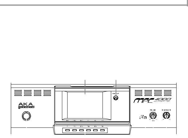
Top panel
Upper part of the top panel
2 |
3 |
|
|
|
|
|
|
|
|
|
|
|
|
|
|
|
|
|
|
|
|
|
|
|
|
|
|
|
|
|
|
|
|
|
|
|
|
1 |
4 |
5 6 |
7 |
|||||
A [POWER] button: This switch turns the power on/off.
B Display: This is a backlit liquid crystal display (LCD). The angle can be adjusted in five positions.
C [CONTRAST] knob: This knob adjusts the contrast of the display.
D[F1]–[F6] keys: These keys are used to access the pages indicated in the bottom row of the display, and to execute the function assigned to each key. The actual function will depend on the screen that is currently displayed.
E[GAIN] switch: This switch selects the gain of the signal that is input from the [LINE/MIC] jacks or [PHONO] jacks. Set this to HI if mics are connected to the [LINE/MIC] jacks, or to LOW if a line-level device such as a CD player is connected. When inputting signals from a turntable connected to the [PHONO] jacks, always set this switch to LOW.
F[REC GAIN] knob: This knob adjusts the recording level of the signal that is input from the [LINE/MIC] jacks or [PHONO] jacks. The inner knob adjusts the right channel, and the outer knob adjusts the left channel.
G [MAIN VOLUME] knob: This adjusts the output level of the signal that is sent from the [MAIN OUT] jacks.
1
Chapter 1—Parts and their functions
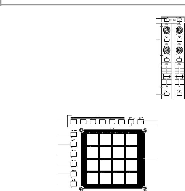
Q-LINK section
You can assign internal MPC4000 parameters or MIDI messages to the knobs and sliders of this section, and control them in realtime.
A[SETUP] key: This key accesses the Q-LINK Setup page, where you can select the parameter that will be assigned to each knob and slider.
B[SEQUENCE] key: This key accesses the Q-LINK Sequence page, where you can record Q-LINK values and play them back automatically.
C[Q1]–[Q4] knobs: A control change or any of different internal parameters can be assigned to these knobs, allowing you to control values in realtime.
D[Q5]/[Q6] sliders: These sliders are used to control internal parameters and control changes in realtime. The parameters and control changes that can be assigned to the sliders are the same as for the Q-LINK control knobs.
E[ACTIVE] keys: These keys specify whether knob/slider operations will take priority over the events recorded in the sequencer. If these keys are on (LED lit), the actual positions of the knobs/sliders will take priority even if changes for the same parameters are recorded in the sequencer.
Pad section
1
2
3
4

5
In this section you can operate the velocity-sensitive pads, and make various settings for them.
2 |
4 |
|
3 |
5 |
|
6 |
|
7 |
|
|
1 |
8 |
|
9 |
|
J |
|
APads 1–16: These are velocity sensitive pads used to play the MPC4000’s sampler section and external MIDI devices. In some pages, these pads are used to select tracks or sequences.
BPAD BANK [A]–PAD BANK [F] keys: These keys switch the combination of sounds/note numbers that are assigned to pads 1–16 (the “pad bank”). The PAD BANK [A]–PAD BANK [F] keys select pad banks A–F respectively.
C[NEXT SEQUENCE] key: This key accesses the Next Sequence page, where you can use the pads to switch sequences in realtime.
D[TRACK MUTE] key: This key accesses the Track Mute page, where you can use the pads to switch track muting in realtime.
E[Q-LINK SEQUENCE] key: This key is an on/off switch for the Q-LINK Sequence function, which lets you play back Q-LINK values.
F[PAD ASSIGN] key: This key accesses the Pad Assign page, where you can change the note numbers that are assigned to the pads.
G[FULL LEVEL] key: When this key is on (LED lit), sounds will be played at the maximum velocity (127) regardless of how strongly you strike the pads.
H[16 LEVEL] key: When this key is on (LED lit), the sound of a specific pad will be assigned to all sixteen pads, allowing you to play the sound using sixteen gradations of velocity.
2
Top panel
I[ERASE] key: This key is used to erase events from within a track. Events can be erased in realtime while overdubbing, or individual events can be erased while the sequencer is stopped. For details, refer to p.22, 24, 27.
J[NOTE REPEAT] key: When you hold down this key and press one of the pads, the sound assigned to that pad will be triggered repeatedly. The interval of the repetitions can be adjusted in a range from an 8th note to a 64th note triplet.
Data entry section |
1 |
This section lets you input numerical values.
A Numeric keys: These keys are used to input a numerical value directly into the selected field in the display.
B [ENTER] key: This key finalizes the value that was input by the numeric keys.
C [–/+] keys: These keys switch the sign (negative/positive) of the value that was input by the numeric keys.
Mode section
In this section you can switch between the various modes of MPC4000. Each key
3 2
corresponds to the following mode.
1 2 3
4 5 6
7 8 9 J K L M N O
A [RECORD] key: Record mode |
I |
B [SAMPLE] key: Sample mode |
J |
C [PROGRAM] key: Program mode |
K |
D [MULTI] keyMulti mode: |
L |
E [MIXER] key: Mixer mode |
M |
F [EFFECT] key: Effect mode |
N |
G [SAVE] key: Save mode |
|
H [LOAD] key: Load mode |
O |
|
[GLOBAL] key: Global mode
[SONG] key: Song mode
[MISC.] key: Misc. mode
[MIDI] key: MIDI mode
[MAIN] key: Main mode
[SEQ EDIT] key: Sequence Edit mode
[STEP EDIT] key: Step Edit mode
Control section
In this section you can perform basic sequencer operations such as locate/playback/record, and change the setting of various fields that are shown in the display.
|
7 |
|
1 |
9 |
|
5 |
8 |
|
2 |
J |
|
6 |
||
K |
||
|
||
3 |
|
|
|
L |
|
4 |
|
M N O P Q
A[TIMING CORRECT] key: This key is an on/off switch for the Timing Correct function, which corrects the timing of the note data that is being recorded in the sequencer. Timing Correct is enabled if the LED is lit, and the note data will be recorded at timing intervals of the currently selected note value.
B[MASTER TEMPO] key: This key selects the tempo source used for sequencer playback. If the LED is lit, all sequences will play at a common tempo. If the LED is dark, each sequence will play at its own tempo.
C[UNDO SEQ] key: This key is used to cause events recorded in the sequencer to revert to their previous condition (the Undo function). The LED will light if Undo is available.
3
Chapter 1—Parts and their functions
D[TAP TEMPO] key: This key is used to manually specify the tempo. Striking this key repeatedly will automatically set the tempo to the corresponding quarter-note interval.
E[WINDOW] key: This key opens a window for making detailed settings. When you move the cursor to a specific field in the display and press this key, a window for that field will open. Press this key once again to close the window.
F[SHIFT] key: This key is used in conjunction with other keys as a shortcut for certain functions, or to specify a range.
GCURSOR [π]/[†]/[√]/[®] keys: These keys are used to move the cursor up/down/left/right in the display.
H [JOG] dial: This dial adjusts the value of the parameter at which the cursor is located.
IBLOCK CURSOR [π]/[†] keys: If the currently displayed page is divided into blocks, these keys move the cursor upward or downward between blocks.
JSTEP [<]/[>] key: These keys are used to move backward or forward within the sequence in units of one step. By holding down the [GO TO] key and pressing one of these keys, you can move to the event that is immediately before or after the current location.
K[GO TO] key: This key is used to move the current location to a specified locate point, or to access the Locate window where you can register a locate point. For details on the Locate window, refer to page 14.
LBAR [<<]/[>>] keys: These keys are used to move backward or forward within the sequence in units of one measure. By holding down the [GO TO] key and pressing one of these keys, you can move to the start point or end point of the sequence.
M[REC] key: When you hold down this key and press the [PLAY] key or [PLAY START] key, recording on the sequencer will begin. If the track contains previously-recorded events, they will be replaced by the new events.
N[OVER DUB] key: This key has essentially the same function as the [REC] key, with the difference that newly recorded events will be added to the track without erasing the previously-recorded events.
O [STOP] key: This key stops sequence playback or recording.
P [PLAY] key: This key starts playback or recording from the current location within the sequence.
Q [PLAY START] key: This key starts playback or recording from the start point of the sequence.
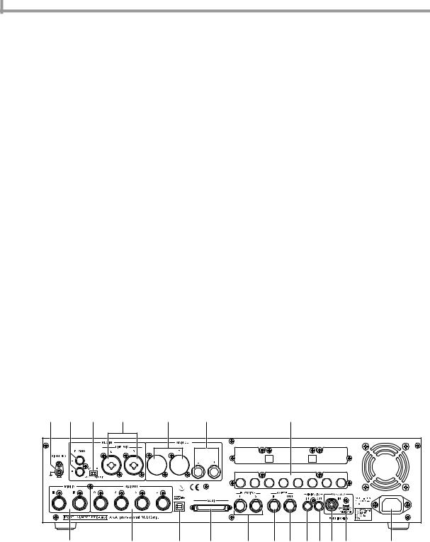
Rear panel
1 2 |
4 |
3 |
5 |
6 |
|
R |
|
7 |
|
8 |
9 |
J |
K |
L M NOP Q |
S |
A [SIGNAL GND] terminal: Connect the grounding wire of your turntable to this terminal. |
|||||||
BREC IN [PHONO] jacks: These are turntable input jacks.
*A phono equalizer will be applied to compensate the frequency response of the signal that is input to these jacks. Do not connect any device other than a turntable to these jacks.
CREC IN [LINE/MIC] jacks: Mics or line level devices such as CD players can be connected to these jacks. Either XLR or phone plug cables can be connected. Balanced phone plug connections are also supported.
D[INPUT SELECT] switch: This switch selects the input signal. The signal from the [PHONO] jacks will be input if this switch is in the PHONO position, and the signal from the [LINE/MIC] jacks will be input if this switch is in the LINE/MIC position.
E[MAIN OUT] jacks (XLR): These are balanced main output jacks that output the signal from the sampler section and the metronome click sound. Cables with XLR plugs can be connected.
4
Front panel
F[MAIN OUT] jacks (phone): These are balanced main output jacks for connecting phone plug cables. They output the same signal as the [MAIN OUT] (XLR) jacks.
G[MIDI IN I]/[MIDI IN II] connectors: These connectors receive MIDI messages. MIDI messages can be received independently at each connector.
H[MIDI OUT A]–[MIDI OUT D] connectors: These connectors transmit MIDI messages. MIDI messages can be transmitted independently from each connector A–D.
I[USB] connector (slave): This connector allows the MPC4000 to be connected to a computer (Windows/Macintosh) for file transfer or remote control.
JSCSI connector: This is a D-sub half-pitch 50-pin (high pitch 50 pin) connector for connecting SCSI-compatible devices. SCSI-type CD-ROM drives or hard disks can be connected. For details on SCSI connections and supported devices, contact your Akai dealer or Akai Professional M.I Service Department.
K[FOOT SWITCH 1]/[FOOT SWITCH 2] jacks: Foot switches can be connected to these jacks to perform operations such as punch-in/out.
L[SMPTE IN] jack: This jack receives SMPTE time code (LTC) from an external device. Use this when you want an external device to be the time code master, and the MPC4000 to operate in synchronization with the external device.
M[SMPTE OUT] jack: This jack transmits SMPTE time code from the MPC4000 to an external device. Use this when you want the MPC4000 to be the time code master, and an external device to operate in synchronization with it.
N[DIGITAL IN] jack: This is a coaxial type digital input jack. The digital output jack of a CD player or DAT can be connected to this.
O[DIGITAL OUT] jack: This is a coaxial type digital output jack. It outputs the same signal as the [MAIN OUT] jacks.
P[WORDCLOCK IN] jack: This is a BNC jack for receiving a word clock signal from an external device. Use this when the MPC4000’s digital audio signal processing must be synchronized with that of an external digital recorder or digital mixer.
Q[TERMINATOR] switch: This is an on/off switch for word clock termination. If a word clock signal is being supplied from an external device to the MPC4000’s [WORDCLOCK IN] jack, you will normally set this to the ON position.
R Option slot: This slot allows a separately sold interface card to be installed.
SPower supply connector: Connect the included power cable to this connector.
*You must use the cable that is included with the MPC4000.
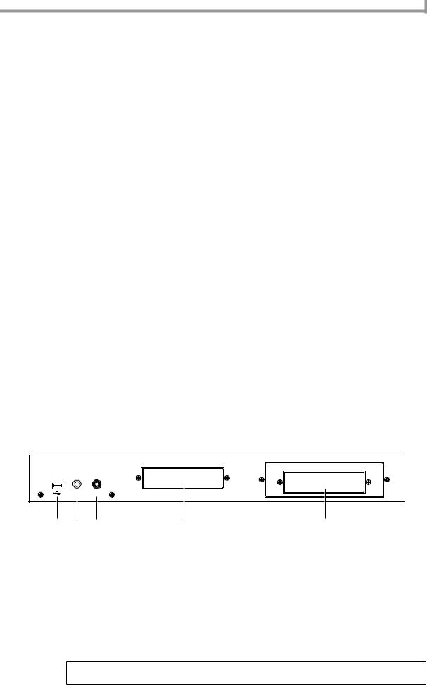
Front panel
PHONES LEVEL
1 2 3 4 5
A[USB] connector (host): This USB connector allows a USB-type CD-ROM drive, removable drive, or USB keyboard etc. to be connected. Unlike the rear panel USB connector, this connector cannot be connected to a computer. For details on USB connections and supported devices, contact your Akai dealer or Akai Professional M.I Service Department.
B[PHONES] jack: This is a stereo phone jack for connecting headphones. It outputs the same signal as the [MAIN OUT] jacks.
C [PHONES LEVEL] knob: This is a dedicated volume knob for the [PHONES] jack.
D 3.5 inch bay: An ATAPI-type internal hard disk or ZIP drive can be installed in this bay.
E5 inch bay: An ATAPI-type CD-ROM drive can be installed in this bay. A 3.5 inch drive can also be installed here. For compatible devices, contact your Akai dealer or Akai Professional M.I Service Department.
Note: If a removable disk drive is installed in the MPC4000, protect the disk by taking it out of the drive when you are not actually loading or saving data on it.
5

Chapter 1—Parts and their functions
Audio/MIDI connections
When connecting external audio or MIDI devices to the MPC4000, make connections as shown in the diagram below.
CD player |
|
Mic |
Monitor speakers |
LINE OUT |
Mixer |
Turntable
LINE OUT R |
Foot switches |
|
|
|
INPUT INPUT |
GND |
LINE OUT L |
MIDI IN 
|
MIDI sound module |
DIGITAL IN |
MIDI OUT |
DIGITAL OUT |
|
|
|
|
|
DAT recorder/MD recorder |
|
|
MIDI keyboard |
to an electrical |
|
|
|
|
|
outlet |
PHONES LEVEL
Headphones
Connecting USB devices
[USB] connectors are provided on the front panel and the rear panel of the MPC4000.
The rear [USB] connector (slave) can be connected to a USB-equipped computer (Windows or Macintosh), allowing you to control the MPC4000 from an editing program.
The front panel [USB] connector (host) can be connected to a USB storage device such as a hard disk or CD-ROM drive to save the MPC4000’s internal data, or to a USB-compatible ASCII keyboard for easier input of names.
PHONES LEVEL |
TYPE A |
TYPE B |
USB port |
|
USB port
CD-ROM Keyboard
PC/MAC
6
Connecting SCSI devices
USB devices support “hot plugging,” which means you can connect or disconnect them even when the power is on. When you connect a USB device, the MPC4000 will recognize it automatically.
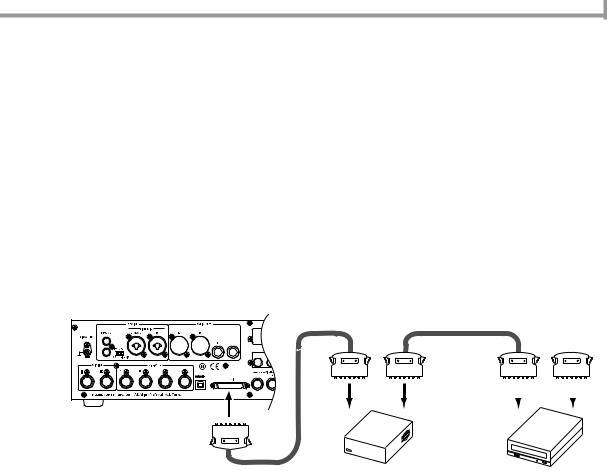
Connecting SCSI devices
The MPC4000’s rear panel has a [SCSI] connector that lets you connect devices such as a SCSI hard disk.
Up to seven SCSI devices (including the MPC4000 itself) can be connected, and each device is distinguished by its own SCSI ID number. Please observe the following cautions when connecting SCSI devices.
•The power of all devices must be turned off before you connect SCSI devices.
•Set the ID numbers of the SCSI devices so that they do not conflict with each other.
•At the factory, the MPC4000 is set to a SCSI ID of 6. However, you may change this if necessary. For details, refer to the PDF reference manual.
•Use high-quality SCSI cables (high impedance cables) to connect the devices.
•You must use a terminator to terminate the last device in the SCSI chain. (The MPC4000 contains an active terminator that is always on.)
• You must turn on the power in the order of SCSI devices → MPC4000.
Terminator
|
|
|
|
|
|
|
|
|
|
|
|
|
|
|
|
|
|
|
|
|
|
|
|
|
|
|
|
|
|
|
|
|
|
|
|
|
|
|
|
|
|
|
|
|
|
|
|
|
|
|
|
|
|
|
|
|
|
|
|
|
|
|
|
|
|
|
|
|
|
|
|
|
|
|
|
|
|
|
|
|
|
|
|
|
|
|
|
|
|
|
|
|
|
|
|
|
|
|
|
|
|
|
|
|
|
|
|
|
|
|
|
|
|
|
|
|
|
|
|
|
|
|
|
|
|
|
|
|
|
|
|
|
|
|
|
|
|
|
|
|
|
|
|
|
|
|
|
|
|
|
|
|
|
|
|
|
|
|
|
|
|
|
|
|
|
|
|
|
|
|
|
|
|
|
|
|
|
|
|
|
|
|
|
|
|
|
|
|
|
|
|
|
|
|
|
|
|
|
|
|
|
|
|
|
|
|
|
|
|
|
|
|
|
|
|
|
|
|
|
|
|
|
|
|
|
|
|
|
|
|
|
|
|
|
|
Hard disk |
|
|
|
CD-ROM |
|||||||
|
|
|
|
|
|
|
|
|
|
|
|
|
|
|
|
|
|
|
|
|
|
|||||||||
|
|
|
|
|
|
|
|
|
|
|
|
|
|
|
|
|
|
|
|
|
|
|||||||||
7

Chapter 2—Introducing the MPC4000
2 Introducing the MPC4000
This chapter describes how the MPC4000 is structured, and explains the special terms you will need to know when using it. This chapter also explains the user interface of the MPC4000, and basic operating procedures.
How the MPC4000 is structured
Broadly speaking, the MPC4000 consists of the following three sections.
•Sampler
•Sequencer
•Pads/controllers
These sections internally communicate with each other using MIDI events (performance data). The following diagram shows how MIDI events will flow within the MPC4000 when it is in the default state.
MIDI sound module
MPC4000
Sampler 
Pads
MIDI sequencer |
MIDI IN/MIDI OUT |
MIDI keyboard
A MIDI note number is assigned to each pad on the top panel, and when you strike a pad, the corresponding note-on message is sent to the sequencer section or the [MIDI OUT] connectors.
The sequencer section records the MIDI events that it receives from the pads or the [MIDI IN] connectors. When you play back the sequencer, these MIDI events are sent to the sampler section or the [MIDI OUT] connectors.
The sampler section receives MIDI events from the sequencer section, pads, and [MIDI IN] connectors, and produces sounds.
Now let’s take a closer look at how each section is structured.
Sampler section
Samples
The sounds of the sampler section are created from pieces of audio waveform data called “samples.” The MPC4000 can use samples with 16-bit or 24-bit quantization and 44.1/48/96 kHz sampling rates (stereo or monaural).
Programs
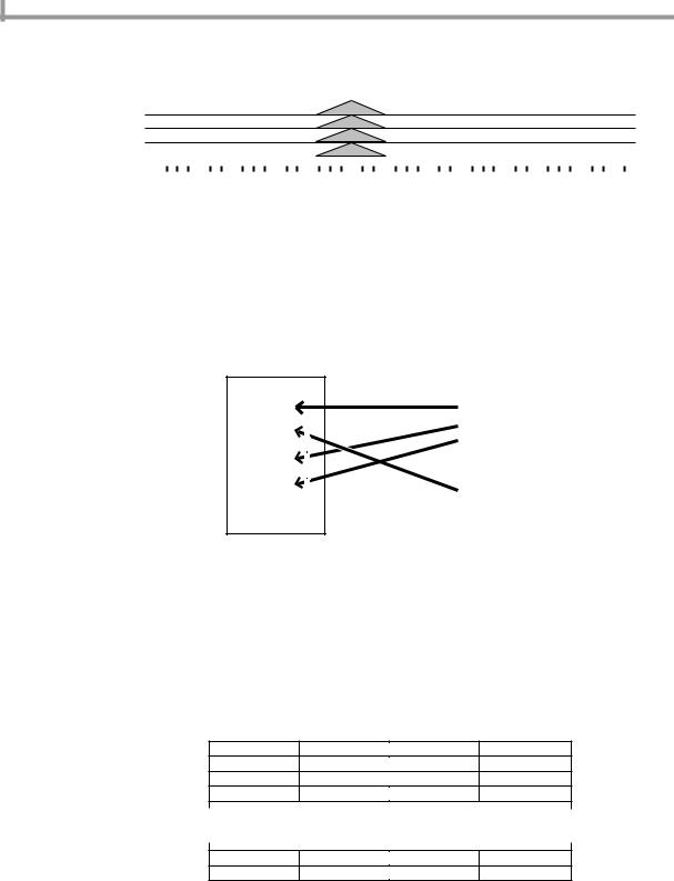
The units of sound used by the sampler section are called “programs.” A program consists of one or more samples (waveform data) together with filter, envelope, LFO and other parameters. The MPC4000 has two types of program.
•Drum programs
This type of program assigns a different sample to each note number. You will use drum programs mainly to play drum or percussion kits, or to play phrase samples.
A drum program provides “zones” (areas) to which you can assign up to four samples for each note number. You can specify the range of velocities that will play each zone. This lets you layer multiple samples, or switch samples by velocity.
When you use the pads to play drums, you will use one of these drum programs. The program will be played according to the note numbers that are assigned to the pads.
8

Sampler section
The following diagram is an example of a drum program in which one sample is assigned to each pad.
Note number: 48 |
Zone1: TOM 1 |
|
|
Note number: 40 |
Zone1: SNARE |
|
|
Note number: 37 |
Zone1: SIDE STICK |
PA D 13 PA D 14 PA D 15 PA D 16
|
|
|
Note number: 53 |
Zone1: RIDE |
PA D 9 |
PA D 10 |
PA D 11 |
PA D 12 |
|
|
|
|
Note number: 43 |
Zone1: TOM 4 |
PA D 5 |
PA D 6 |
PA D 7 |
PA D 8 |
|
|
|
|
Note number: 94 |
Zone1: PEDAL HH |
PA D 1 |
PA D 2 |
PA D 3 |
PA D 4 |
|
The following diagram is an example where two samples are assigned to each pad number. For some note numbers, two samples are crossfaded by velocity.
|
|
PA D 13 |
PA D 14 |
PA D 15 |
PA D 16 |
|
|
PA D 9 |
PA D 10 |
PA D 11 |
PA D 12 |
Note number: 48 |
Zone1: TOM1 |
Zone2: TOM5 |
|
|
|
|
|
PA D 5 |
PA D 6 |
PA D 7 |
PA D 8 |
Note number: 40 |
Zone1: SNARE |
Zone2: RIM |
|
|
|
|
|
PA D 1 |
PA D 2 |
PA D 3 |
PA D 4 |
Note number: 37 |
Zone1: SIDE STICK |
Zone2: SIDE STICK2 |
|
|
|
Note number: 53 |
|
Zone1: RIDE |
|
Zone2: Crach Cym |
Note number: 43 |
|
Zone1: TOM4 |
|
Zone2: TOM8 |
|
|
|||
Note number: 94 |
|
|
||
|
Zone1: PEDAL HH |
|
Zone2: MID HH |
|
•Key group programs
This type of program uses a region of consecutive note numbers to play a sample at varying pitches. You will use key group programs to play sounds such as bass or piano.
The region of note numbers to which one sample is assigned is called a “key group,” and the range of notes that play a key group is called the “key span.”
Just as for a drum program, you can use up to four zones in a key group.
The following diagram is an example of a single sample assigned to a key group that consists of only one zone. The key span for this key group is specified as the entire keyboard.
Keygroup 1/Zone 1: Samp 1
The following diagram shows an example using two key groups, each with their own key span. The two key groups are cross-faded by pitch.
|
|
|
|
KG1/ZN1: Samp 1 |
|
|
|
|
|
|
|
|
|
KG2/ZN1: Samp 2 |
||||||||||||||||||||||||||||||
|
|
|
|
|
|
|
|
|
|
|
|
|
|
|
|
|
|
|
|
|
|
|
|
|
|
|
|
|
|
|
|
|
|
|
|
|
|
|
|
|
|
|
|
|
|
|
|
|
|
|
|
|
|
|
|
|
|
|
|
|
|
|
|
|
|
|
|
|
|
|
|
|
|
|
|
|
|
|
|
|
|
|
|
|
|
|
|
|
|
|
|
|
|
|
|
|
|
|
|
|
|
|
|
|
|
|
|
|
|
|
|
|
|
|
|
|
|
|
|
|
|
|
|
|
|
|
|
|
|
|
|
|
|
|
The following diagram shows an example using two key groups, each with four zones. The two key groups are switched by pitch.
|
|
|
|
KG1/ZN4: Samp 7 |
|
|
|
|
|
|
|
|
|
KG2/ZN4: Samp 8 |
||||||||||||||||||||||||||||||
|
|
|
|
KG1/ZN3: Samp 5 |
|
|
|
|
|
|
|
|
|
KG2/ZN3: Samp 6 |
||||||||||||||||||||||||||||||
|
|
|
|
KG1/ZN2: Samp 3 |
|
|
|
|
|
|
|
|
|
KG2/ZN2: Samp 4 |
||||||||||||||||||||||||||||||
|
|
|
|
KG1/ZN1: Samp 1 |
|
|
|
|
|
|
|
|
|
KG2/ZN1: Samp 2 |
||||||||||||||||||||||||||||||
|
|
|
|
|
|
|
|
|
|
|
|
|
|
|
|
|
|
|
|
|
|
|
|
|
|
|
|
|
|
|
|
|
|
|
|
|
|
|
|
|
|
|
|
|
|
|
|
|
|
|
|
|
|
|
|
|
|
|
|
|
|
|
|
|
|
|
|
|
|
|
|
|
|
|
|
|
|
|
|
|
|
|
|
|
|
|
|
|
|
|
|
|
|
|
|
|
|
|
|
|
|
|
|
|
|
|
|
|
|
|
|
|
|
|
|
|
|
|
|
|
|
|
|
|
|
|
|
|
|
|
|
|
|
|
9
Chapter 2—Introducing the MPC4000
The following diagram also shows two key groups, each with four zones. However, the difference here is that the two key groups are crossfaded.
|
|
|
|
KG1/ZN4: Samp 7 |
|
|
|
|
|
|
|
|
|
KG2/ZN4: Samp 8 |
||||||||||||||||||||||||||||||
|
|
|
|
KG1/ZN3: Samp 5 |
|
|
|
|
|
|
|
|
|
KG2/ZN3: Samp 6 |
||||||||||||||||||||||||||||||
|
|
|
|
KG1/ZN2: Samp 3 |
|
|
|
|
|
|
|
|
|
KG2/ZN2: Samp 4 |
||||||||||||||||||||||||||||||
|
|
|
|
KG1/ZN1: Samp 1 |
|
|
|
|
|
|
|
|
|
KG2/ZN1: Samp 2 |
||||||||||||||||||||||||||||||
|
|
|
|
|
|
|
|
|
|
|
|
|
|
|
|
|
|
|
|
|
|
|
|
|
|
|
|
|
|
|
|
|
|
|
|
|
|
|
|
|
|
|
|
|
|
|
|
|
|
|
|
|
|
|
|
|
|
|
|
|
|
|
|
|
|
|
|
|
|
|
|
|
|
|
|
|
|
|
|
|
|
|
|
|
|
|
|
|
|
|
|
|
|
|
|
|
|
|
|
|
|
|
|
|
|
|
|
|
|
|
|
|
|
|
|
|
|
|
|
|
|
|
|
|
|
|
|
|
|
|
|
|
|
|
•Multi
A “multi” consists of performance settings for one or more programs that allow the program(s) to be played from the pads or sequencer.
Within a multi, a “part” refers to each of the areas for which you make individual settings for a program. One multi lets you use up to 128 parts.
To play the MPC4000’s programs, you assign programs to parts within the multi, and specify the level, output destination, pan, and effect send level etc. for each part.
Multi
Part |
|
|
Program A |
|
|
|
|||
|
|
|
Program B |
|
Part |
|
|
Program C |
|
|
|
|
||
|
Program D |
|||
Part |
|
|
||
|
||||
|
|
|
Program E |
|
|
|
|
||
Part |
|
|
|
|
Program F |
||||
|
||||
• |
||||
• |
||||
|
|
|
||
• |
• |
|||
|
|
|
||
• |
• |
|||
|
|
|
||
• |
• |
|||
|
|
|
||
The MPC4000’s internal memory can store numerous multis. By loading a different multi from internal memory, you can instantly switch the settings of all parts.
Sequencer section
Tracks and sequences
“Sequences” are the basic unit from which an MPC4000 song is created. The MPC4000 lets you create up to 128 sequences in internal memory, and you can specify the length (1–999 measures), tempo, and time signature separately for each sequence.
Each internal area within a sequence that records a performance you play on the pads or a MIDI keyboard is called a “track.” A sequence consists of 128 tracks.
Track 1
Track 2
Track 3
Track 4
• • • •
Track 127
Track 128
The MIDI events recorded in the 128 tracks can be sent to the sampler section or transmitted from the [MIDI OUT] connectors. You can freely select the output destination for each track.
•Songs
You can arrange multiple sequences in the desired playback order to create a “song.” To create a song, you specify the number of the sequence, and how many times it will be played. By specifying up to 250 such “steps,” you can create a song consisting of sequences placed in the desired order.
A song you create can be saved as is, or can be converted into a sequence and written.
Step 1 |
Step 2 |
Step 3 |
Step 4 |
Step 5 |
|
Sequence A |
Sequence |
Sequence |
Sequence A |
Sequence A |
|
B |
C |
(repeat x 1) |
|||
|
|
||||
|
|
|
|
|
10
Pad section
Pad section
Pads 1–16
The top panel contains sixteen velocity-sensitive pads. These pads are a user interface that corresponds to the keyboard of a synthesizer. However, the pads differ from a MIDI keyboard in that you can freely assign a note number to each pad.
If you have selected a drum program, you can assign a different drum/percussion sound to each pad and play them. If you have selected a key group program, you can assign the necessary pitches to the pads to play a melody.
Pad banks
A set of note numbers assigned to pads 1–16 is called a “pad bank.” The MPC4000 provides six pad banks, A–F. By switching pad banks you can use the sixteen pads to play 96 different sounds (or different pitches).
About the memory of the MPC4000
The programs, samples, multis, sequences, and songs we have discussed so far are all held in the internal memory of the MPC4000. However, internal memory is volatile, and will be lost when you turn off the power.
This means that if you want to keep your data, you must save it on an external or internal storage device (e.g., hard disk).
You can store data to (or load data from) a storage device in units of programs, samples, multis, sequences, and songs.
You also have the option of loading/saving the sequences/songs of the sequencer section and the programs/samples/multis of the sampler section as a single collection of data.
Basic operation on the MPC4000
Here’s how to perform the basic operations that are common to each screen of the MPC4000.
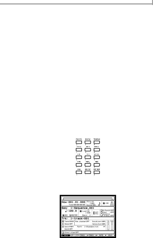
Switching modes
In order to perform an operation on the MPC4000, you must first use the keys of the mode section (→ p.3) to access the desired mode.
The screen will switch according to the mode you selected. The following illustration shows the Main mode screen that you will see when you turn on the power. Operations for the Sequencer section are mainly performed in this screen. If a different screen is shown, you can press the [MAIN] key of the mode section to access this screen.
11
Chapter 2—Introducing the MPC4000
Accessing a page
Each mode consists of multiple screens. Each of the screens in a mode is called a “page.” Each page is divided into blocks that contain related items, and each block contains one or more items that you can set. An area in which you can change the setting of an item is called a “field”
Block 
Fields
Operating the function keys
Six function keys ([F1]–[F6] keys) are placed below the display in the top panel.
The function of these function keys will change according to the mode or page you select. The lowest line of the display will indicate the function key functions that can be used in the currently selected mode and page. By pressing the corresponding function key, you can execute the displayed function.
For example in the Main mode Main page, the following functions are assigned to the function keys.
In this page, pressing the [F2] key (TR LIST) will access the Main mode Track List page. Pressing the [F3] key (TRACK+) or [F4] key (TRACK–) will switch the track numbers displayed in the main page.
Editing a value
When you want to edit the value of a field in the screen, move the cursor (the highlighted area) to that field, and turn the [JOG] dial.
To move the cursor within a block, use the CURSOR [π]/[†]/[√]/[®] keys. To move the cursor directly to the block above or below, use the BLOCK CURSOR [π]/[†] keys.
Place the cursor at the appropriate location, and turn the [JOG] dial to change the value of that field.
Accessing a popup window
Some items in the screen have a popup window that lets you set various options. To access the popup window, move the cursor to the field for that item, and press the [WINDOW] key.
As an example, here’s how to access the clock function that is built into the MPC4000.
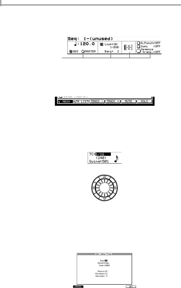
1.Press the [GLOBAL] key, and then press the [F1] key (GLOBAL).
The Global page will appear.
2.Use the CURSOR [π]/[†] keys to move the cursor to the Date field, and press the [WINDOW] key.
The Set Date/Time popup window will appear.
12
Editing a value
3.Use the CURSOR [π]/[†] keys to select the item that you want to set, and use the [JOG] dial to set the current date and time.
4.Press the [F6] key (SET).
The popup window will close, and the specified date and time will be set for the internal clock.
Note: The specified date and time will be used as the time stamp when saving a file.
Hint: A popup window may also appear when you set the value of certain fields, or when you execute a function assigned to the [F1]–[F6] keys.
Editing a name
When you want to edit a sequence name or program name, move the cursor to the name field, and turn the [JOG] dial to access the following popup window.
In this window, use the CURSOR [√]/[®] keys to move the cursor to the character that you want to edit, and turn the [JOG] dial to select a character. When you are finished, press the [F6] key (ENTER) to finalize the name.
Locating to a specific place
The MPC4000 gives you various ways to change the current time location within a sequence or song.
•Using the Now field to specify the measure/beat/tick
Screens such as the main page have a Now field that shows the current measure/beat/tick. You can move the cursor to any of the following fields and turn the [JOG] dial to change the current location.
1 |
2 |
3 |
A Measure field |
|
B Beat field
C Tick field
These fields specify the current location in measures, beats, and ticks. In the Tick field, you can use the CURSOR [√]/[®] keys to switch the tick unit (10 ticks/1 tick).
•Using the STEP [<][>] keys/BAR [<<]/[>>] keys/[GO TO] keys
If the MPC4000 is in a state in which you can play back a sequence or song, you can use the STEP [<]/[>] keys, BAR [<<]/[>>] keys, and [GO TO] key to move the current location forward or backward. Each key has the following operation.
|
|
Keys |
|
|
|
Result |
|
|
|
|
|
|
|
|
|
|
|
|
|||
STEP [<]/[>] keys |
|
|
|
|
Move the current location forward or backward by the amount |
|||||
|
|
|
|
you specified in Timing Correct. |
|
|
|
|||
|
|
|
|
|
|
|
|
|
|
|
|
|
|
|
|
|
|
|
|||
[GO TO] key + STEP [<]/[>] keys |
Move the current location in steps of the events recorded in the |
|||||||||
track (refer to Reference for the type of events). |
|
|
||||||||
|
|
|
|
|
|
|
|
|
||
|
|
|
|
|
|
|
|
|
|
|
BAR [ |
]/[ |
] keys |
|
|
|
Move the current location in step of one measure. |
|
|
||
<< >> |
|
|
|
|
|
|
|
|
|
|
[GO TO] key + BAR [ |
<< |
]/[ |
>> |
] keys |
Move to the beginning (BAR [ |
] key) or end (BAR [ |
>> |
] |
||
|
|
|
|
|
<< |
|
||||
|
|
|
|
|
|
|
key) of the sequence. |
|
|
|
|
|
|
|
|
|
|
|
|
|
|
13

Chapter 2—Introducing the MPC4000
Hint: You are free to change the functions assigned to these keys. For details, refer to the PDF reference manual.
•Using the Locate popup window
If the MPC4000 is in a state in which you can play back a sequence, you can press the [GO TO] key to access a popup window where you can perform locate operations. IN this window you can memorize the current location as a locate point, or specify a locate point in measures/beats/ticks.
1A Go to field: Here you can specify the locate
destination in measures/beats/ticks.
B Locate 1 field – Locate 3 field: Here you
2 |
|
|
|
|
|
|
|
can specify locate points. The MPC4000 can |
|
|
|
|
|
|
|
|
remember up to three locate points. |
||
|
|
|
|
|
|
|
|
||
|
|
|
|
|
|
|
|
C [F1] key (CLOSE): This key closes the win- |
|
|
|
|
|
|
|
|
|
dow and locates to the position of the Go to |
|
|
|
|
|
|
|
|
|
field. |
|
|
|
|
|
|
|
|
|
D [F2] key (LOCATE 1)–[F4] key (LOCATE 3): |
|
|
|
|
|
|
|
|
|
||
|
|
|
|
|
|
|
|
These keys locate to the corresponding locate |
|
|
|
|
|
|
|
|
|
||
3 |
4 |
5 |
|||||||
points. |
|||||||||
|
|
|
|
|
|
|
|
||
E [F6] key (CAPTURE): This key inputs the current location of the sequence into the currently selected field.
Hint: Locate points 1/2 are also used as the auto punch-in/out points (→ p.24).
Playing a program
Immediately after you have turned on the power of the MPC4000, the internal memory does not contain any programs. In order for you to use pads 1–16 to play a program from the sampler section, you must load a program from an external or internal storage device into memory, and assign it to a part. Here’s how to do this.
1.If you are using an external storage device, make sure that the storage device is connected correctly and that its power is turned on.
For details on connecting storage devices, refer to p.6, 7.
2.Press the Load section [LOAD] key.
The MPC4000 will enter Load mode.
3.Move the cursor to the Disk block in the upper part of the page, and turn the [JOG] dial to access the following popup window.
In this window you can select the storage device from which you want to load a program.
4. Use the CURSOR [π]/[†] keys or the [JOG] dial to select a storage device.
14
Editing a value
5.Press the [F5] key (SELECT).
The contents of the storage device will be displayed as a tree in the file list block in the upper part of the screen.
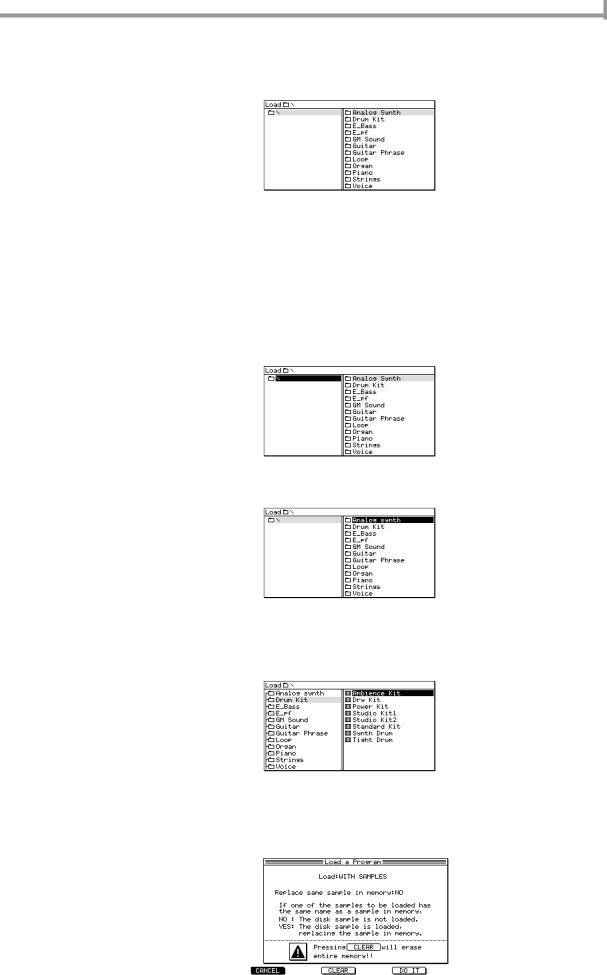
6.Move the cursor to the View field in the center of the display, and use the [JOG] dial to select “PROGRAM.”
In the View field you can select the type of files that will be displayed in the file list. If you choose PROGRAM, only program files will be displayed.
7.Move the cursor to the file list, and use the CURSOR [π]/[†]/[√]/[®] keys to select the file you want to load.
In the file list, use the CURSOR [√]/[®] keys to move between levels, and the CURSOR [π]/[†] keys to select a file or folder within the current level.
For example when you first access a storage device, the left side of the file list will by the [ROOT] folder, and the right side will display the files or folders contained in the [ROOT] folder.
When the [ROOT] folder is selected, press the CURSOR [®] key once to move the cursor to the right side of the file list.
If you want to move to a level below the [ROOT] folder, use the CURSOR [π]/[†] keys to select the folder and then press the CURSOR [®] key to scroll the tree display to the right. The right side of the file list will now show the contents of the newly selected folder. (To return to the next upper level, press the CURSOR [√] key.)
To select a file from the currently selected level (folder), use the CURSOR [π]/[†] keys to move the cursor to the folder.
8.When you have selected a program file, press the [F6] key (DO IT button).
The Load a Program window will appear.
15
Chapter 2—Introducing the MPC4000
9.Make sure that the Load field is set to WITH SAMPLES, and press the [F5] key (DO IT button).
The MPC4000 will load the program. If the Load field is set to WITH SAMPLES, the necessary samples will be loaded into memory along with the program.
The program has now been loaded into memory. In order to play the program, you will need to assign it to a part.
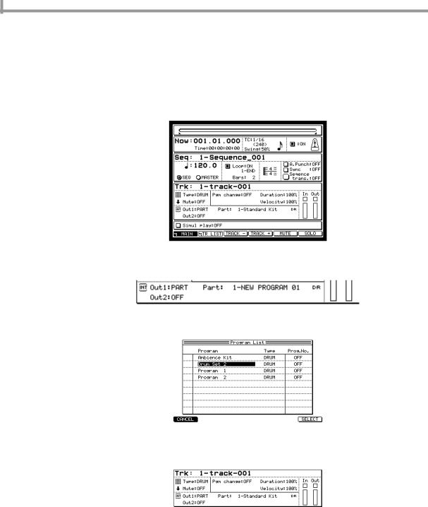
10.Press the mode section [MAIN] key.
The main page will appear. Here you can create and play sequences.
11.In the Track block located in the middle of the page, make sure that the Out1 field is set to PART, and the PART field is set to a value of 1.
12.Move the cursor to the right side of the PART field, and turn the [JOG] dial.
The following popup window will appear.
13.Turn the [JOG] dial to select the program, and press the [F6] key (SELECT) to finalize the program.
The program has now been assigned to part 1. Now you can strike the pads to play the selected program.
16
Creating and editing a sequence
3 Creating and editing a sequence
This chapter explains how to record MIDI events into a sequence, and how to edit the recorded MIDI events.
About sequences
A “sequence” is the smallest unit from which an MPC4000 song is made up. You can specify the length (1–999 measures), tempo, and time signature of each sequence. On the MPC4000, you can create a song that consists of only one sequence, or you can create separate sequences and then arrange them later into a complete song.
The internal memory of the MPC4000 contains 128 sequences. When you turn on the power, all sequences will be empty. To create a new sequence, you must select an empty sequence and record or edit it.
Note: The contents internal memory will be cleared when you turn off the power, and the sequences you create will be lost. If you want to keep your sequences, you must save them to a storage device before turning off the power.
A sequence consists of 128 tracks. Each track can independently record the performance data (MIDI events) such as note-on/off and control change that is sent from the pads and from the [MIDI IN I]/[MIDI IN II] connectors.
Track 1
Track 2
Track 3
Track 4
• • • •
Track 127
Track 128
There are two types of track.
• |
DRUM .............. |
This type of track lets you view and edit the recorded MIDI events in a matrix-type |
|
|
graphic editor (→ p.27). This type of track is convenient for drum or percussion sounds. |
• |
INST ................. |
This type of track lets you view and edit the recorded MIDI events in a piano-roll type |
|
|
graphic editor (→ p.27). This is convenient for pitched sounds such as bass or piano. |
Hint: You are free to change the track type even after MIDI events have been recorded in the track.
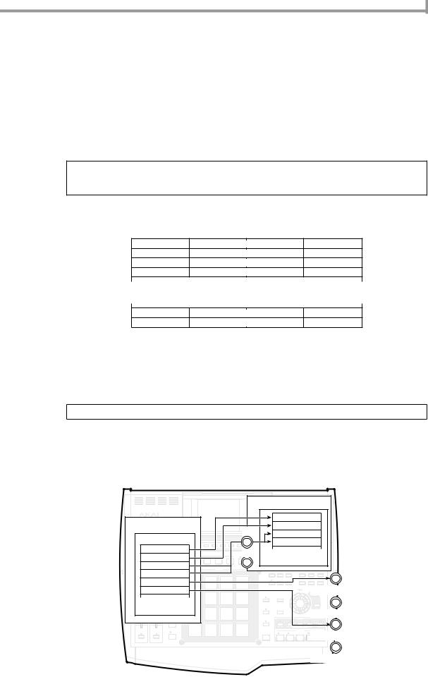
The recorded MIDI events are sent to the output destination that you specify for each track. You can choose from the following outputs.
•[MIDI OUT A] connector – [MIDI OUT D] connector
•INT-A/INT-B (virtual MIDI reception ports of the sampler section)
•Specific parts of the sampler section
|
|
|
|
|
|
|
|
|
|
|
|
|
CONTRAST |
|
|
|
|
|
|
|
|
|
|
|
|
|
|
|
|
|
|
|
Sampler |
|
|
|
|
||
Sequencer section |
|
|
|
|
|
|
|
|
|
|
|
|
Part |
|
|
||||
|
|
|
|
|
|
|
|
|
|
|
|
REC GAIN |
MAIN VOLUME |
||||||
|
|
|
|
|
|
INTF 6 |
A |
|
|
GAIN |
Part |
|
|
||||||
|
|
|
|
|
|
|
|
|
|
|
|
|
|
|
|||||
|
|
|
|
|
|
|
|
|
|
|
|
|
HIGH |
|
|
|
|||
|
|
|
|
|
|
|
|
|
|
|
|
|
LOW |
|
|
|
|||
|
|
|
|
|
F 1 |
F 2 |
F 3 |
|
F 4 |
F 5 |
|
|
|
L R |
|
|
|||
Sequence |
|
|
|
|
|
|
|
|
|
|
|
|
|
|
|
Part |
|
|
|
|
|
|
F 1 |
F 2 |
F 3 |
|
F 4 |
F 5 |
F 6 |
|
|
|
|
|
Part |
|
|
||
|
|
|
|
|
|
|
|
|
|
|
|
|
|
|
|
|
|
|
|
SETUP |
SEQUENCE |
|
|
|
|
|
|
|
|
|
|
|
|
|
|
|
• |
|
|
|
Track 1 |
|
|
|
|
|
|
|
|
|
|
|
|
|
|
SAMPLE |
PROGRAM |
||
|
|
|
|
|
|
|
|
|
|
|
|
|
|
|
RECORD |
||||
|
|
|
|
|
|
|
|
|
|
|
|
|
|
|
• |
|
|
||
Q 1 |
Q 2 |
|
|
|
PAD BANK |
|
|
|
|
|
|
|
|
|
|
|
I |
J |
K |
|
|
|
|
|
|
|
|
|
|
|
NEXT |
|
TRACK |
|
|
|
•MULTI |
|
|
|
|
A |
|
B |
C |
D |
|
|
E |
F |
INTSEQUENCE |
BMUTE |
7 |
8 |
9 |
MIXER |
EFFECT |
||
|
Track 2 |
|
|
|
|
|
|
|
|
|
|
|
|
|
|
• |
M |
N |
|
|
|
|
|
|
|
|
|
|
|
|
|
|
|
|
|
|
L |
||
|
A |
|
B |
C |
D |
|
|
E |
|
F |
G |
|
H |
4 |
5 |
6 |
SAVE |
LOAD |
GLOBAL |
ACTIVE |
ACTIVE |
|
|
|
|
|
|
DRUMS |
|
|
|
|
|
|
|
|
|
|
|
Track 3 |
|
|
|
|
|
|
|
|
|
|
|
|
O |
P |
Q |
||||
|
|
Q-LINK |
|
|
|
|
|
|
|
|
|
|
|
1 |
2 |
3 |
SONG |
MISC. |
MIDI |
|
|
SEQUENCE |
|
|
|
|
|
|
|
|
|
|
|
||||||
|
Track 4 |
|
PA D 13 |
P LOOP |
PA D 14 |
P |
TO |
PA D 15 |
P FROM |
PA D 16 |
PL AY |
|
|
|
|
|
|
|
|
|
|
|
|
|
|
|
|
|
|
|
|
|
|
|
|
|
|
||
Q 3 |
Q 4 |
|
|
|
|
|
|
|
|
|
|
|
|
|
|
|
R |
S |
T |
|
& |
|
|
|
|
|
|
|
|
|
|
|
|
|
0 |
ENTER |
MAIN |
SEQ EDIT |
STEP EDIT |
|
|
PAD |
|
|
|
|
|
|
|
|
|
|
|
|
|
|
|
|
|
|
|
ASSIGN |
|
|
|
|
|
|
|
|
|
|
|
|
|
|
|
|
|
|
Track 5 |
|
|
|
|
|
|
|
|
|
|
|
|
|
|
U |
V |
W |
|
|
|
6 |
|
|
|
|
|
|
|
|
|
|
|
|
|
|
CURSOR |
|
|
ACTIVE |
ACTIVE |
|
PA D 9 |
|
PA D 10 |
|
|
PA D 11 |
|
PA D 12 |
|
|
|
|
|
JOG |
|
|
|
|
|
|
|
|
|
|
|
|
|
|
|
|
|
|
|
||||
Track# |
|
|
|
|
|
|
|
|
|
|
|
|
|
|
[MIDI OUT A] connector |
||||
|
|
FULL |
|
|
|
|
|
|
|
|
|
|
TIMING CORRECT |
|
|
|
|
|
|
|
|
LEVEL |
|
|
|
|
|
|
|
|
|
|
|
|
WINDOW |
|
|
|
|
|
|
|
|
|
|
|
|
|
|
|
|
|
|
|
|
|
|
BLOCK |
|
Q 5 |
Q 6 |
|
|
|
|
|
|
|
|
|
|
|
X |
|
|
|
|
CURSOR |
|
|
|
16 |
|
PA D 5 |
|
PA D 6 |
|
|
PA D 7 |
|
PA D 8 |
|
MASTER TEMPO |
|
|
|
|
|
|
|
|
LEVELS |
|
|
|
|
|
|
|
|
|
|
|
|
SHIFT |
|
|
|
|
|
• |
|
|
|
|
|
|
|
|
|
|
|
Y |
|
|
|
[MIDI OUT B] connector |
||
|
! |
|
|
|
|
|
|
|
|
|
|
|
|
|
|
|
|||
|
• |
ERASE |
|
|
|
|
|
|
|
|
|
|
UNDO SEQ |
|
|
|
LOCATE |
|
|
|
|
|
|
|
|
|
|
|
|
|
|
|
STEP |
GO TO |
BAR |
|
|||
|
|
|
|
PA D 1 |
|
PA D 2 |
|
|
PA D 3 |
|
PA D 4 |
|
|
|
|
|
|
|
|
|
• |
|
|
|
|
|
|
|
|
|
|
|
|
|
|
|
|
|
|
|
|
|
|
|
|
|
|
|
|
|
|
|
Z |
|
|
EVENT |
|
START |
END |
|
• ( |
|
|
|
|
|
|
|
|
|
|
|
|
|
|
|
|
|
|
|
|
NOTE |
|
|
|
PLAY / REC |
|
|
ACTIVE |
ACTIVE |
REPEAT |
TAP TEMPO |
REC |
OVER |
STOP |
PLAY |
PLAY |
|
|
|
DUB |
START |
[MIDI OUT C] connector
)
[MIDI OUT D] connector
17
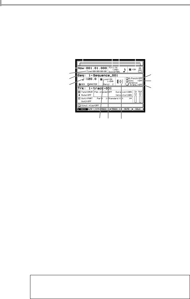
Chapter 3—Creating and editing a sequence
Preparations for creating a sequence
Before you can record MIDI events in a track, you must specify certain parameters such as the number of measures, the time signature, and the tempo.
1.Press the [MAIN] key.
The main page will appear. Most of the steps involved in creating a sequence are performed in this page. Set the parameters of the sequence in the sequence block described below.
1 |
4 5 |
6 |
||||||
2 |
|
|
|
|
|
|
|
|
|
|
|
|
|
|
|
|
|
|
|
|
|
|
|
|
|
|
|
|
|
|
|
|
|
|
|
3 |
|
|
|
|
|
|
L |
|
7 |
|
|
|
|
|
|
|
M |
|
|
|
|
|
|
|
|
|
8
N
9 J K
APosition bar: This shows the current position within the sequence. The full length of the bar graph corresponds to the length of that sequence.
B Now field: This shows the current position within the sequence in measures/beats/ticks.
C Time field: This shows the current position within the sequence in hours/minutes/seconds/frames.
DTC field: Here you can specify the note value that will be the minimum unit for timing correction (quantization).
ESwing field: In this field you can specify the amount of “swing” by which the backbeats will be moved forward or backward. This will be displayed if you have selected 1/8, 1/16, 1/32, or 1/64 in the TC field.
F Metronome field: Here you can switch the metronome on/off.
GSeq field: Here you can select the sequence that you want to record or edit. The field will show the name of the currently selected sequence.
H Tempo field: Here you can set the tempo of the sequence.
ILoop field: Here you can switch loop playback on/off for the sequence. The field immediately below the Loop field lets you change the loop region. The loop region is shown as in the position bar.
JBars field: This opens the Change Bars popup window which lets you specify the number of measures in the sequence.
KTime signature field: This opens the Change Time Signature popup window which lets you specify the time signature of the sequence.
L A.Punch field: Here you can switch the auto punch-in/out function on/off.
M Sync field: Here you can switch synchronization with external devices on/off.
NSequence trans. field: This lets you transpose an entire INST type track in a range of –12–+12 semitones.
2.Move the cursor to the Seq field, and turn the [JOG] dial to select an empty sequence.
When an empty sequence is selected, the Seq field will indicate “x- (Unused)” (x will be a sequence number in the range of 1–128). An empty sequence will have default settings of time signature = 4/4, measures = 2, and tempo = 120.
Hint: When you turn on the power, all sequences will be empty.
When you record MIDI events into a sequence, a sequence name of “Sequence_xxx” (where xxx is a sequence number in the range of 1–128) will be assigned automatically.
If the cursor is in the Seq field, you can press the [WINDOW] key to access the Sequence popup window in which you can change the sequence name or edit the entire sequence (→ p.36).
3. Move the cursor to the Bars field, and turn the [JOG] dial.
18
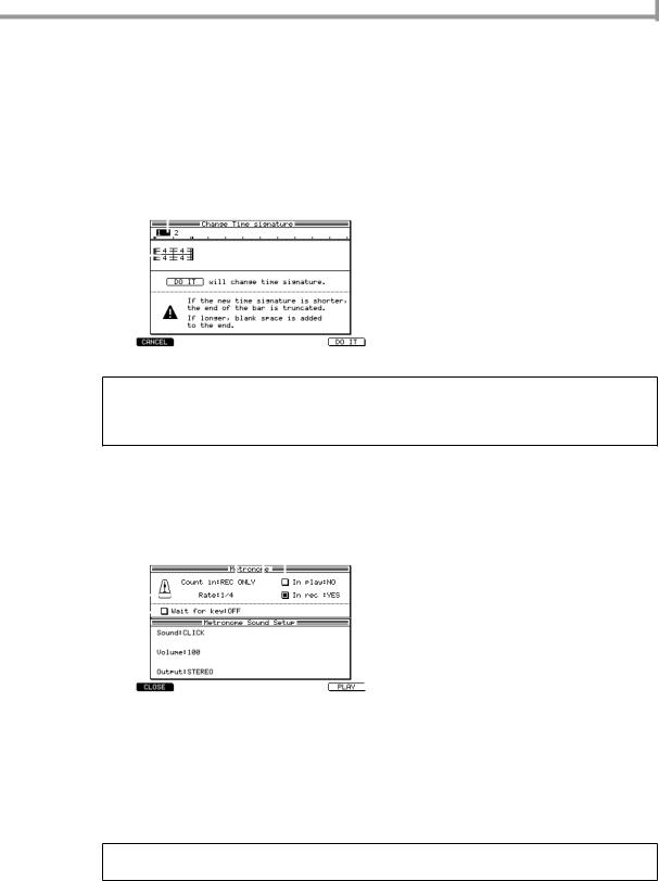
Realtime input
The Change Bars popup window will appear. In this window you can specify the number of measures in the sequence.
4.Turn the [JOG] dial to specify the number of measures, and then press the [F6] key (DO IT) to finalize the setting.
If you increased the setting, measures will be added after the current measure. If you decreased the setting, measures will be deleted from the end of the sequence.
5.If you want to change the time signature of the sequence, move the cursor to the field that displays the time signature, and turn the [JOG] dial to access the following popup window.
1 |
A Measure numbers: These indicate the mea- |
|||
|
|
|
|
sure numbers within the sequence. |
2 |
|
|
|
B Time signature field: Here you can specify |
|
|
|
||
|
|
|
the time signature of the sequence. You can |
|
|
|
|
||
select a time signature in the range of 1/4–16/4, 1/8–16/18, 1/16–16/16, 1/32–32/32.
6. Move the cursor to the time signature field, and turn the [JOG] dial to set the time signature.
Hint: By moving the cursor to the measure number and turning the [JOG] dial to specify a measure number, you can change the time signature mid-way through the sequence.
You can select multiple measures by holding down the [SHIFT] key and pressing the CURSOR [®] key. By changing the time signature in this state, you can change the time signature for all measures within the selected range.
7.To finalize your changes, press the [F6] key (DO IT).
The popup window will close.
8.If you want to make settings for the metronome, move the cursor to the Metronome field and press the [WINDOW] key.
The Metronome popup window will appear.
1 3 2 |
A Count in field: Specify how the pre-count |
||||||
|
|
|
|
|
|
|
will be sounded; OFF (pre-count= off), REC |
4 |
|
|
|
|
|
|
ONLY (only when recording), or REC+PLAY |
|
|
|
|
|
|
||
|
|
|
|
|
|
(when recording or playing). |
|
|
|
|
|
|
|
||
5 |
|
B In Play field: Specify whether the metronome |
|
||
|
|
|
|
|
will sound while the sequence plays back. |
|
|
C In Rec field: Specify whether the metronome |
|
|
will sound while the sequence is being recorded. |
DRate field: Select the note value at which the metronome will sound. Choose from a range of 1/4 (quarter notes)–1/32(3) (thirty-second note triplets).
EWait for key field: If you turn this field ON, recording will begin the instant you press a pad or play your MIDI keyboard.
9.Make settings for each field, and then press the [WINDOW] key to close the popup window.
10.Make sure that the setting in the metronome field is ON.
11.Move the cursor to the tempo field, and turn the [JOG] dial to set the tempo as desired.
Hint: You can also set the tempo in realtime by tapping the [TAP TEMPO] key. This method is convenient when you want to match the tempo of a sequence to a sampled rhythm loop.
12.If you want the sequence to loop as you play or record it, make sure that the setting of the Loop field is ON.
You are now finished with preparations for creating a sequence.
Realtime input
Here we will explain how your performance on the pads or a MIDI keyboard can be recorded on a track in realtime.
Realtime-recording a drum program
Here’s how you can use the pads to play a drum program of the internal sampler or a rhythm machine connected to a [MIDI OUT] connector, and record your performance on an empty track.
19

Chapter 3—Creating and editing a sequence
1.If you want to use a drum program of the internal sampler as your sound source, load the desired program into the internal memory of the MPC4000.
2.If you want to use an external rhythm machine as your sound source, connect one of the [MIDI OUT A]–[MIDI OUT D] connectors to the MIDI IN connector of your MIDI sound source.
MIDI IN |
MIDI sound source |
3.Press the [MAIN] key to access the main page.
The Track block of the main page lets you select the track that you want to record, and specify the output destination.
4 5 6
1
2
3
87 9
A Trk field: Selects the track that you want to record.
B Type field: Selects the type of track.
C Play field: Switches the track on/off.
DPgm Change field: Specifies the program change number that will be sent to the output destination when you play back the sequence.
EVelocity field: Specifies an offset value of 0–200% that will be applied to the velocities of all note events when the track is played back.
FDuration field: Specifies an offset value of 0–200% that will be applied to the duration of all note events when the track is played back.
G Out1 field
HOut2 field: These fields specify the output destinations of the track. By setting the OUT1 field and OUT2 field to different output destinations, you can transmit the events of one track to two output destinations.
IPart field: Selects the part number(s) and program(s) to which the track will be sent. This field will be displayed only if PART is selected as the output destination for the Out1/Out2 fields.
J K
JCh field: Selects the MIDI channel(s) to which the track will be sent. This field will be displayed only if you have selected OUT-A–OUT-D or INT-A/INT-B as the output destination for Out1/Out2.
KDevice field: This field displays the device name that you have assigned to the devices connected to the [MIDI OUT A]–[MIDI OUT D] connectors. To assign a device name, move the cursor to this field and press the [WINDOW] key.
4.Move the cursor to the Trk field, and turn the [JOG] dial to select the track that you want to record.
Immediately after the power is turned on, all tracks in the sequence will be empty. Empty tracks will be assigned a track name of “(Unused).”
Hint: You can directly switch to the next upper or lower track by using the [F4] key (–) or [F5] key (+).
When you record MIDI events, a track name of “track_xxx” (where xxx is a track number 001–128) will be assigned.
When the cursor is located at the Trk field, you can press the [WINDOW] key to access the Track popup window, where you can edit the track name or edit the entire track.
20
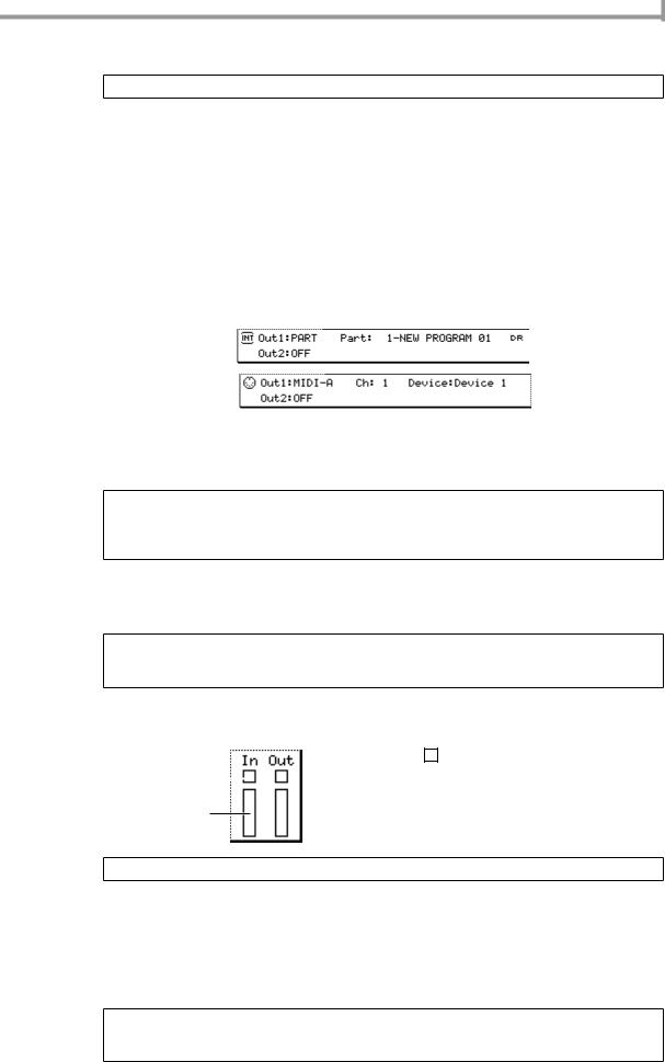
Realtime input
5.Make sure that the Type field is set to DRUM.
Hint: You can change this setting later as necessary.
6.Move the cursor to the Out1 field, and turn the [JOG] dial to select one of the following output destinations for the track.
PART............... A specific part of the sampler section OUT A ............ [MIDI OUT A] connector
OUT B ............ [MIDI OUT B] connector OUT C ............ [MIDI OUT C] connector OUT D ............ [MIDI OUT D] connector
INT-A.............. Virtual MIDI input port A of the sampler section INT-B .............. Virtual MIDI input port B of the sampler section
You will normally choose PART if you want to play a program on the internal sampler, or OUT A–OUT D if you want to play an external rhythm machine.
The fields at the right of the OUT1 field will change as follows, depending on the output destination you selected.
7.Move the cursor to the PART field or the Ch field, and turn the [JOG] dial to specify a part number (if you selected PART) or a MIDI channel (if you selected OUT A–OUT D).
When you strike the pads or play back the sequencer, the MIDI events will be transmitted to the part or MIDI channel you specified here.
Hint: If you selected a virtual MIDI port (INT-A/INT-B) of the sampler section as the output destination, specify the MIDI channel in the same way as described above. (Set it to match the MIDI receive channel of the part you want to play.)
You can use the same steps to set the Out2 field.
8.If you selected PART as the output destination, move the cursor to the right of the PART field and select the desired part number. Then move the cursor to the right again, select the drum program that you will play using this part.
The program will be assigned to the part you selected. For details on how to select a program, refer to p.14.
Hint: If desired, you can specify a program change number by moving the cursor to the Pgm Change field and turning the [JOG] dial. When you play back the sequence, the program change specified by this field will be sent to the output destination.
9.Strike the pads, and make sure that you can hear the program or MIDI sound source.
If you want to switch pad banks, press the PAD BANK [A]–[F] keys. The display for the In field will change according to the pad that you strike.
|
|
A |
|
: This will blink when a MIDI event is |
1 |
|
|
received. |
|
|
|
|
|
|
BBar: This will indicate the velocity value of the 2 note event that is received. A longer bar indi-
cates a larger velocity value.
Hint: The Out field shows the output status of the track. The contents of the display are the same as for the In field.
10.Move the cursor to the TC field, and turn the [JOG] dial to select one of the following choices as the minimum timing interval at which note events will be recorded in the track.
1/8...8th notes, 1/8(3)...8th note triplets, 1/16...16th notes, 1/16(3)...16th note triplets, 1/32...32nd notes, 1/32(3)...32nd note triplets, 1/64...64th notes, 1/64(3)...64th note triplets,
OFF(96)...10 ticks (1/96th of a quarter note), OFF...Timing Correct=off (1/960th of a quarter note) Timing Correct is a function that aligns the timing of note events to the specified note value interval as they are recorded in the track. If Timing Correct is turned on, the [TIMING CORRECT] key LED will light.
Hint: You may also record note events with Timing Correct turned off, and apply timing correct later. For details, refer to the PDF reference manual.
Use the [TIMING CORRECT] key to switch Timing Correct on/off.
21

Chapter 3—Creating and editing a sequence
11.To start recording, hold down the [REC] key and press the [PLAY] key. Then play the pads while you listen to the metronome.
The [REC] key and [PLAY] key LEDs will light, and recording will begin on the currently selected track.
Hint: If you press the [PLAY START] key instead of the [PLAY] key, recording will always start from the beginning of the sequence. If you press the [OVER DUB] key instead of the [REC] key, the existing MIDI events will be kept, and the newly-recorded MIDI events will be added to them.
If the Loop field is set to ON/1-END, and you reach the end of the sequence, you will automatically return to the beginning and continue recording. At this time, the [OVER DUB] key LED will light instead of the [REC] key LED, and the newly-recorded MIDI events will be added.
12.To stop recording, press the [STOP] key.
When you record or edit a track, the [UNDO SEQ] LED will light. If you press the [UNDO SEQ] key in this state, the track will return to the state in which it was before you modified it.
13.To hear the content that you recorded, press the [PLAY] key (or the [PLAY START] key).
14.To erase a note event that you input by mistake, hold down the [OVER DUB] key and press the [PLAY] key. Then immediately before the note event that you want to erase, hold down the [ERASE] key and press the corresponding pad.
The corresponding note event(s) will be erased as long as you hold down the pad.
1 |
2 |
3 |
4 |
1 |
2 |
3 |
4 |
Pad 1 |
|
|
|
|
|
|
|
Pad 2 |
|
|
|
|
|
|
|
|
|
|
|
• |
|
|
|
|
[ERASE] key + Pad 1 |
|
• |
[ERASE] key + Pad 2 |
|
||
|
|
• |
|
||||
|
|
|
|
|
|
|
|
|
|
|
|
• |
|
|
|
1 |
2 |
3 |
4 |
1 |
2 |
3 |
4 |
Pad 1 |
|
|
|
|
|
|
|
Pad 2 |
|
|
|
|
|
|
|
|
|
|
|
• |
|
|
|
|
|
|
|
• |
|
|
|
|
|
|
|
• |
|
|
|
|
|
|
|
• |
|
|
|
15. Save the sequence if desired (→ |
p.38). |
|
|
|
|
|
|
Realtime-recording a key group program
Here’s how you can use the pads or a MIDI keyboard to play a key group program of the internal sampler or an external MIDI sound module, and record your performance.
1.If you want to use a key group program as your sound source, load the desired program into the MPC4000’s internal memory.
2.If you want to use an external MIDI sound module as your sound source, connect your MIDI sound module to the MPC4000 (→ p.6).
3.If you want to use an external MIDI keyboard as the controller instead of the pads of the MPC4000, connect the MIDI OUT of your keyboard to the MPC4000’s [MIDI IN I] connector or [MIDI IN II] connector.
You can use a MIDI keyboard connected to the [MIDI IN I]/[MIDI IN II] connectors to play programs and record sequences in the same way as when using the pads.
MIDI IN |
MIDI keyboard |
4.Press the [MAIN] key to access the main page of Main mode.
5.Move the cursor to the Trk field, and turn the [JOG] dial to select a new track.
6.Move the cursor to the Type field, and turn the [JOG] dial to change the setting to INST.
22
Loading...