


MFC42
Table of contents
 Loading...
Analog Filter Module
WARNING!!
To reduce the risk of fire or electric shock, do not expose this apparatus to rain or moisture.
CAUTION
RISK OF ELECT RIC SHO C K
DO NOT OPEN
CAUTION: TO REDUCE THE RISK OF ELECTRIC SHOCK,
DO NOT REMOVE COVER (OR BACK).
NO USER-SERVICEABLE PARTS INSIDE.
REFER SERVICING TO QUALIFIED SERVICE PERSONNEL.
THE SYMBOLS ARE RULED BY UL STANDARDS (U.S.A.)
The lightning flash with arrowhead symbol , within an equilateral triangle, is intended to
alert the user to the presence of uninsulated “dangerous voltage” within the product’s
enclosure; that may be of sufficient magnitude to constitute a risk of electric shock to
persons.
The exclamation point within an equilateral triangle is intented to alert the user to the
presence of important operating and maintenance (servicing) instructions in the literature
accompanying the appliance.
1-En
5B-En
9/25/2001 Rev. 4
WARNING
WARNING: WHEN USING ELECTRIC PRODUCTS, BASIC PRECAUTIONS SHOULD ALWAYS
BE FOLLOWED, INCLUDING THE FOLLOWING:
WARNING
The MFC42 is designed to be used in a standard household environment.
Power requirements for electrical equipment differ from area to area. The operating voltage of this
MFC42 is preset at the factory according to its intended destination. However, before connecting,
check to see that the VOLTAGE SELECTOR on the rear panel is set to the correct voltage for your
area. If not, please set it correctly before plugging in the power cord. If in doubt, consult a qualified
electrician or AKAI professional dealer.
120 V AC @ 60 Hz for USA and Canada
230 VAC @ 50 Hz for Europe
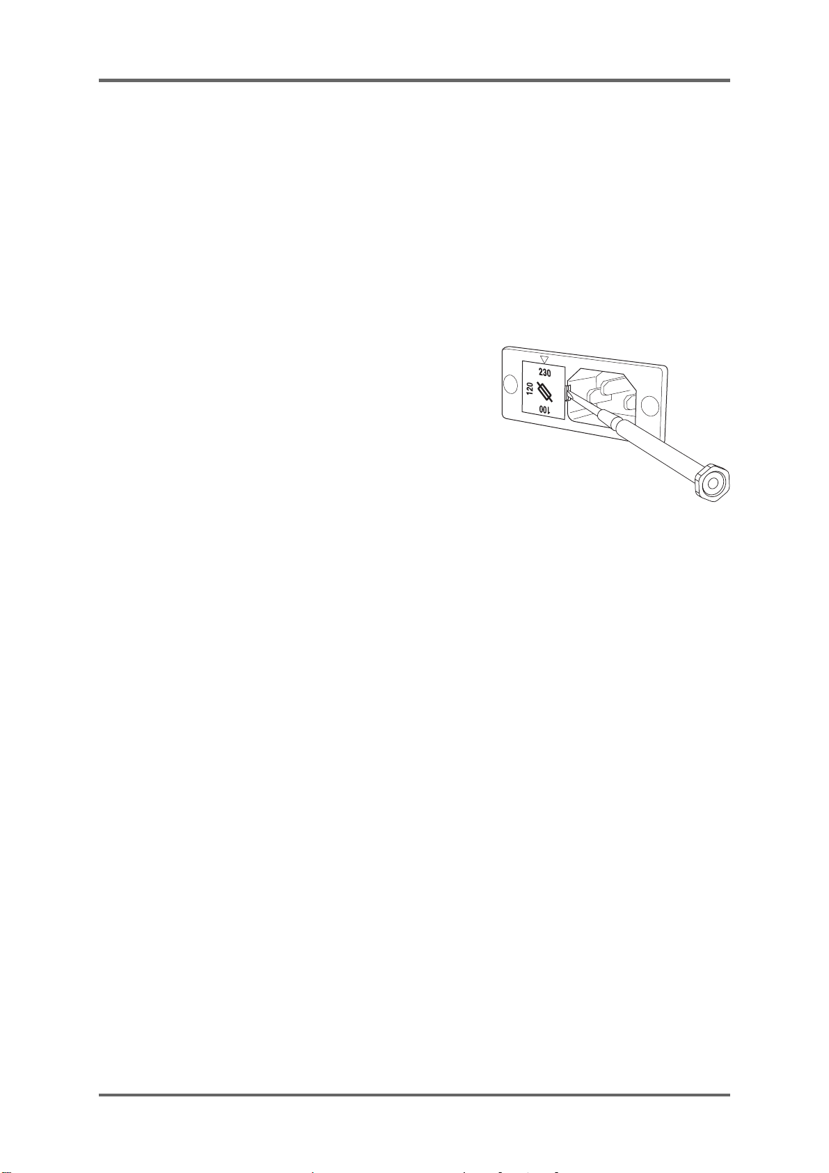
If the VOL T AGE SELECTOR is not set correctly for your area:
Confirm that the power cord is disconnected.
Remove the VOLTAGE SELECTOR with a screw driver and
replace it so that the correct voltage for your area is lined with
the marker. Also, change the fuse according to the chart
indicated on the rear panel as necessary.
PROTECTING YOURSELF AND THE MFC42
• Never touch the AC plug with wet hands.
• Always disconnect the MFC42 from the power supply
by pulling on the plug, not the cord.
• Allow only an AKAI professional dealer or qualified professional engineer to repair or reassemble
the MFC42. Apart from voiding the warranty, unauthorized engineers might touch live internal
parts and receive a serious electrical shock. There are no serviceable parts inside.
• Do not put, or allow anyone to put any object, especially metal objects, into the MFC42.
• Use only a household AC power supply. Never use a DC power supply.
• If water or any other liquid is spilled into or onto the MFC42, disconnect the power , and call your
dealer.
• Make sure that the unit is well-ventilated, and away from direct sunlight.
• To avoid damage to internal circuitry , as well as the external finish, keep the MFC42 away from
sources of direct heat (stoves, radiators, etc.).
• Avoid using aerosol insecticides, etc. near the MFC42. They may damage the surface, and
may ignite.
• Do not use denatured alcohol, thinner or similar chemicals to clean the MFC42. They will damage
the finish.
• Modification of this equipment is dangerous, and can result in the functions of the MFC42 being
impaired. Never attempt to modify the equipment in any way.
• Make sure that the MFC42 is always well-supported when in use (either in a specially-designed
equipment rack, or on a firm level surface).
• When installing the MFC42 in a 19” rack system, always allow 1U of ventilated free space
above it to allow for cooling. Make sure that the back of the rack is unobstructed to allow a clear
airflow .
• In order to assure optimum performance of your MFC42, select the setup location carefully,
and make sure the equipment is used properly. Avoid setting up the MFC42 in the following
locations:
1. In a humid or dusty environment
2. In a room with poor ventilation
3. On a surface which is not horizontal
4. Inside a vehicle such as a car, where it will be subject to vibration
5. In an extremely hot or cold environment
i
WARNING
For U.K. Customers Only
WARNING
THIS APPARATUS MUST BE EARTHED
IMPORTANT
This equipment is fitted with an approved non-rewireable UK mains plug.
To change the fuse in this type of plug proceed as follows:
1) Remove the fuse cover and old fuse.
2) Fit a new fuse which should be a BS1362 5 Amp A.S.T.A or BSI approved type.
3) Refit the fuse cover.
If the AC mains plug fitted to the lead supplied with this equipment is not suitable for your type of
AC outlet sockets, it should be changed to an AC mains lead, complete with moulded plug, to the
appropriate type. If this is not possible, the plug should be cut off and a correct one fitted to suit the
AC outlet. This should be fused at 5 Amps.
If a plug without a fuse is used, the fuse at the distribution board should NOT BE GREATER than
5 Amp.
PLEASE NOTE: THE SEVERED PLUG MUST BE DESTROYED TO AVOID A POSSIBLE
SHOCK HAZARD SHOULD IT BE INSERTED INTO A 13 AMP SOCKET
ELSEWHERE.
The wires in this mains lead are coloured in accordance with the following code:
GREEN and YELLOW — Earth
BLUE — Neutral
BROWN — Live
As the colours of the wires in the mains lead of this apparatus may not correspond with the coloured
markings identifying the terminals in your plug, please proceed as follows:
The wire which is coloured GREEN and YELLOW must be connected to the terminal which is
marked with the letter E or with the safety earth symbol or coloured GREEN or coloured
GREEN and YELLOW.
The wire which is coloured BLUE must be connected to the terminal which is marked with the
letter N or coloured BLACK.
The wire which is coloured BROWN must be connected to the terminal which is marked
with the etter L or coloured RED.
THIS APPARATUS MUST BE EARTHED
Ensure that all the terminals are securely tightened and no loose strands of wire exist.
Before replacing the plug cover, make certain the cord grip is clamped over the outer sheath of the
lead and not simply over the wires.
ii
6D-En
WARNING
FCC WARNING
This equipment has been tested and found to comply with the limits for a Class B digital device
pursuant to Part 15 of the FCC rules. These limits are designed to provide reasonable protection
against harmful interference in a residential installation. This equipment generates, uses, and
can radiate radio frequency energy and, if not installed and used in accordance with the
instructions, may cause harmful interference to radio communications. However, there is no
guarantee that interference will not occur in a particular installation. If this equipment does
cause harmful interference to radio or television reception, which can be determined by turning
the equipment off and on, the user is encouraged to try to correct the interference by one or
more of the following measures:
• Reorient or relocate the receiving antenna.
• Increase the separation between the equipment and receiver.
• Connect the equipment into an outlet on a circuit different from that to which the receiver is
connected.
• Consult the dealer or an experienced radio/TV technician for help.
21B-En
AVIS POUR LES ACHETEURS CANADIENS DU MFC42
Le présent appareil numérique n’ément pas de bruits radioélectriques dépassant les limites
applicables aux appareils numériques de la Class B prescrites dans le Règlement sur le
brouillage radioélectrique édicté par le ministère des Communications du Canada.
27-F
This digital apparatus does not exceed the Class B limits for radio noise emissions from digital
apparatus set out in the Radio Interference Regulations of the Canadian Department of
Communications.
27-En
VENTILATION
Do not prevent the unit’s ventilation, especially by placing the unit on the soft carpet, in a
narrow space, or by placing objects on the unit’s chassis—top, side, or rear panels. Always
keep the unit’s chassis at least 10 centimeters from any other objects.
31C-En
CHANGES OR MODIFICATIONS NOT EXPRESSL Y APPROVED BY THE MANUF ACTURER
FOR COMPLIANCE COULD VOID THE USER’S AUTHORITY TO OPERATE THE
EQUIPMENT.
32-En
COPYRIGHT NOTICE
The AKAI MFC42 contains and uses software in ROMs. This software, and all related
documentation, including this OperatorOs Manual, contain proprietary information which is
protected by copyright laws. All rights are reserved. No part of the software or its documentation
may be copied, transferred or modified. You may not modify, adapt, translate, lease, distribute,
resell for profit or create derivative works based on the software and its related documentation or
any part thereof without prior written consent from AKAI professional M.I. Corp., Yokohama,
Japan.
iii

WARNING
WARRANTY
AKAI professional M.I. Corp. warrants its products, when purchased from an authorized “AKAI professional”
dealer, to be free from defects in materials and workmanship for a period of 12 (twelve) months from the date
of purchase. Warranty service is effective and available to the original purchase only, and only on completion
and return of the AKAI professional
Warranty coverage is valid for factory-authorized updates to AKAI professional instruments and their software,
when their installation is performed by an authorized AKAI professional Service Center, and a properly
completed Warranty Registration has been returned to your “AKAI professional” dealer.
To obtain service under this warranty, the product must, on discovery of the detect, be properly packed and
shipped to the nearest AKAI professional Service Center . The party requesting warranty service must provide
proof of original ownership and date of purchase of the product.
If the warranty is valid, AKAI professional will, without charge for parts or labor, either repair or replace the
defective part(s). Without a valid warranty , the entire cost of the repair (parts and labor) is the responsibility of
the product’s owner.
AKAI professional warrants that it will make all necessary adjustments, repairs and replacements at no cost
to the original owner within 12 (twelve) months of the purchase date if:
1) The product fails to perform its specified functions due to failure of one or more of its components.
2) The product fails to perform its specified functions due to defects in workmanship.
3) The product has been maintained and operated by the owner in strict accordance with the written
instructions for proper maintenance and use as specified in this Operator’s Manual.
Before purchase and use, owners should determine the suitability of the product for their intended use, and
owner assumes all risk and liability whatsoever in connection therewith. AKAI professional shall not be liable
for any injury, loss or damage, direct or consequential, arising out of use, or inability to use the product.
The warranty provides only those benefits specified, and does not cover defects or repairs needed as a result
of acts beyond the control of AKAI professional, including but not limited to:
1) Damage caused by abuse, accident, negligence. AKAI professional will not cover under warranty any
original factory disk damaged or destroyed as a result of the owner’s mishandling.
2) Damage caused by any tampering, alteration or modification of the product: operating software,
mechanical or electronic components.
3) Damage caused by failure to maintain and operate the product in strict accordance with the written
instructions for proper maintenance and use as specified in this Operator’s Manual.
4) Damage caused by repairs or attempted repairs by unauthorized persons.
5) Damage caused by fire, smoke, falling objects, water or other liquids, or natural events such as rain,
floods, earthquakes, lightning, tornadoes, storms, etc.
6) Damage caused by operation on improper voltages.
IMPORTANT NOTE: This warranty becomes void if the product or its software is
AKAI professional shall not be liable for costs involved in packing or preparing the product for shipping, with
regard to time, labor, or materials, shipping or freight costs, or time or expense involved in transporting the
product to and from AKAI professional Authorized Service Center or Authorized Dealer.
AKAI professional will not cover under warranty an apparent malfunction that is determined to be user error,
or owner’s inability to use the product.
THE DURATION OF ANY OTHER WARRANTIES, WHETHER IMPLIED OR EXPRESS, INCLUDING BUT
NOT LIMITED TO THE IMPLIED CONDITION OF MERCHANTABILITY, IS LIMITED TO THE DURATION
OF THE EXPRESS WARRANTY HEREIN.
AKAI professional hereby excludes incidental or consequential damages, including but not limited to:
1) Loss of time.
2) Inconvenience
3) Delay in performance of the Warranty.
4) The loss of use of the product.
5) Commercial loss.
6) Breach of any express or implied warranty , including the Implied Warranty of Merchant-ability , applicable
to this product
Warranty Registration Card within 14 days of purchase.
electronically modified, altered or tampered with in any way.
iv

WARNING
v

CONTENTS
CONTENTS
Chapter 1 Introduction .................................................................................................... 1
Features .................................................................................................................. 1
Names and functions............................................................................................... 2
Front Panel......................................................................................................... 2
Rear Panel ......................................................................................................... 5
Chapter 2 Basic Operation.............................................................................................. 6
Connections............................................................................................................. 6
Signal flow ............................................................................................................... 6
Keywords in basic operation................................................................................... 7
Filter operation......................................................................................................... 8
Changing the sound ................................................................................................ 9
Chapter 3 Advanced Operations .................................................................................. 10
Keywords in advanced operation .......................................................................... 10
Groove Modulator...................................................................................................11
Control the cut-off cyclically with Groove Modulator (TAP TEMPO)...................... 12
Control the cut-off cyclically with Groove Modulator (RATE) ................................. 14
Control the cut-off cyclically with Groove Modulator (MIDI CLOCK SYNC) .......... 14
Shifting LFO waveform with L-R PHASE............................................................... 15
Control on Mono channel with Groove Modulator ................................................. 15
MANUAL TRIGGER .............................................................................................. 16
Controlling Cut-off on Mono and Stereo channels simultaneously........................ 16
Chapter 4 MIDI Function ............................................................................................... 18
MIDI Receive channel setting................................................................................ 18
Recording the knob operation to sequencer.......................................................... 18
Sending the settings via MIDI................................................................................ 19
Chapter 5 Connections to Others ................................................................................ 20
Connecting to Keyboard as external Filter Module................................................ 20
Connecting the Turntable ..................................................................................... 20
Connecting MPC2000/MPC2000XL ...................................................................... 20
Connecting MPC3000 ........................................................................................... 23
Specifications ................................................................................................................ 24
vi

Chapter 1 Introduction
Chapter 1 Introduction
Thank you very much for your purchase of the MFC42. Here, you see its unique features and functions
explained.
Features
Four 2-pole Analog Filters
By the combination of four 2-pole filters, the MFC42 can be configured as 8-pole filter unit maximum. The
sharp cut-off curve and powerful resonance setting allow wide range of sound making possible.
Stereo and Mono Input
Equipped with the Stereo Input and Mono Input independently and can be controlled separately. For
instance, swing the rhythm section from Stereo Input with LFO while the bass from Mono Input being
radically changed by manual filter settings – works as two conventional filter units.
Four Filter types
The four filter settings of High pass, Low pass, Band pass and Notch. The filter type can be switched
directly by the combination of toggle switch settings.
Groove Modulator
The Groove Modulator function offers the control of filter cut-off or resonance synced to the rhythm. By the
combination of Tap Tempo or MIDI Clock Sync functions with LFO/Envelope, the filter cut-off/resonance
can be controlled. It also has the Manual Trigger function to trigger the envelope manually at any point.
MIDI function
Almost all keys and knobs are assigned with the MIDI Control Change number. With the use of external
sequencer, e.g. MPC2000/MPC2000XL, the movement of each key and knob can be recorded and played
back later. The Send Scene function can send all the key and knob settings at once via MIDI. By recording
this data at the beginning of each sequence, the settings can later be recalled when played back.
Analog Phaser/Distortion
The Phase Shifter and Distortion effects are built-in. The addition of these effects to the filter control makes
the sound control more flexible.
2-Band EQ on Output
With the High and Low EQ at the output stage, the tone of output sound can be controlled.
Phono Input
With the Phono Input provided at Stereo Input with LINE/PHONO selector, the turntable can be connected
directly.
2U Rack mountable
The enclosure is shaped so that it can either be rack mounted or placed on desktop to suit your playing
style. With the optional mounting kit, i.e. KIT-MFC, the MFC42 can be mounted on the MPC2000/
MPC2000XL.
1
Chapter 1 Introduction
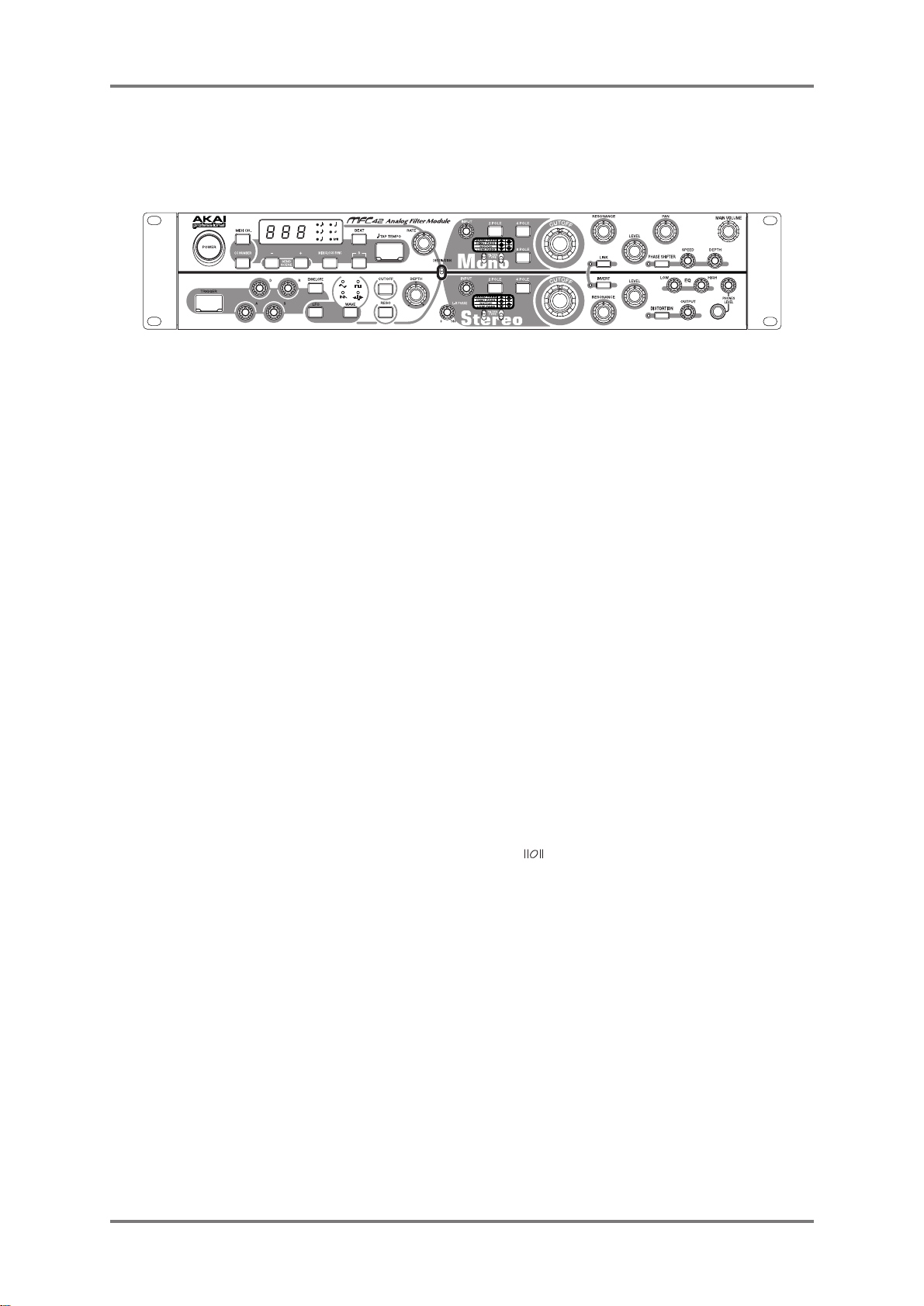
Names and functions
– Front Panel –
1. POWER switch button
Switches the MFC42 on/off.
2. MIDI CH. key
Sets the MIDI channel of the MFC42. Off, 01~16, L01~L16 (L: Local Off)
The value is indicated on 7-seg LED (key flickers while setting).
3. CC NUMBER key
To confirm the CC (Control Change) numbers assigned to the keys and knobs.
The value is indicated on 7-seg LED (key flickers while confirming).
4. +/– keys
Adjust the value of various parameters. Pressing the + and – keys together sends out all parameter
settings via MIDI – Send Scene function.
5. 7-seg LED
Shows the various parameter values, i.e. Tempo, MIDI channel, Control Change number. When
the RATE knob is moved, the flickering speed of upper and lower halves of LED changes
accordingly.
6. MIDI CLOCK SYNC key
Set to ON to sync to the external sequencer or rhythm machine via MIDI Clock. The speed of MIDI
Clock and the note length selected by BEAT key control the speed of LFO or the trigger timing of
envelope (key is lit while ON).
7. BEAT key
Used with the MIDI CLOCK SYNC or TAP TEMPO key, it selects the note length that controls the
speed of LFO or the trigger timing of envelope. One of the six LEDs on their side is always selected
(ON) and the key press toggles the selection. The mark designates the note length of breve
(two whole notes).
8. - 3 - key
Changes the selected note by BEAT key to triplet notes (key is lit while ON).
9. TAP TEMPO key
Tempo is detected by the timing of key presses. The tempo entered and the note selected by
BEAT key set the speed of LFO or the trigger timing of envelope. The tempo entered is indicated
on 7-seg LED (default tempo setting is 120BPM).
10. RATE knob
Sets the speed of LFO or the trigger timing of envelope. The flickering speed of upper and lower
halves of 7-seg LED changes accordingly.
11. TRIGGER key
Manually triggers the envelope for cut-off or resonance at desired point. The trigger is turned on
when the key is pressed and turned off as released. The envelope is set with A/D/S/R
knobs.
2
Loading...