


 Version 2.0
 OPERATOR'S MANUAL
Important Notice
The material in this document is copyright to AKAI professional M.I. Corp., and may not be quoted or reproduced in any form without written permission from the company.
LIMITED SOFTWARE WARRANTY POLICY
All the software provided with, or purchased especially for, AKAI professional products has been tested for functionality. AKAI professional M.I. Corp. will make its best efforts to correct reported software defects for future releases subject to technical practicabilities.
AKAI professional M.I. Corp. makes no warranty or representation either expressed or implied with respect to the system's performance or fitness for a particular purpose.
In no event will AKAI professional M.I. Corp. be liable for direct or indirect damages arising from any defect in the software or its documentation. Further, AKAI professional M.I. Corp. will not accept any liability for any programs, sounds, audio recording or sequences stored in or used with AKAI professional products, including the cost of recovery of such data.
The warranties, remedies and disclaimers above are exclusive and take precedence over all others, oral or written, express or implied, to the extent permitted by law in the geographical area of the product's use. No employee of AKAI professional M.I. Corp., agent, distributor or employee of an agent or distributor is authorised to offer any variation from this policy.
WARNING!!
To prevent fire or shock hazard, do not expose this appliance to rain or moisture.
1-En
CAUTION
RISK OF ELECTRIC SHOCK
DO NOT OPEN
CAUTION: TO REDUCE THE RISK OF ELECTRIC SHOCK
DO NOT REMOVE COVER (OR BACK).
NO USER-SERVICEABLE PARTS INSIDE.
REFER SERVICING TO QUALIFIED SERVICE PERSONNEL.
THE SYMBOLS ARE RULED BY UL STANDARDS (U.S.A.)
The lightning flash with arrowhead symbol, within an equilateral triangle, is intended to alert the user to the presence of uninsulated “dangerous voltage” within the product’s enclosure; that may be of sufficient magnitude to constitute a risk of electric shock to persons.
The exclamation point within an equilateral triangle is intented to alert the user to the presence of important operating and maintenance (servicing) instructions in the literature accompanying the appliance.
5B-En
Caution - use of controls or adjustments or performance. of procedures other than those specified herein may result in hazardous radiation exposure. .
.
This appliance is not equipped with a fully disconnect main power switch. Even when the appliance is turned off, the power supply to the appliance is not completely turned off when the power cord is plugged in. Pull out the power cord when not using the.appliance for long periods.
Oct - 1 / 2005 Rev.1

WARNING: WHEN USING ELECTRIC PRODUCTS, BASIC PRECAUTIONS SHOULD ALWAYS BE FOLLOWED, INCLUDING THE FOLLOWING:
WARNING
The MPC1000 is designed to be used in a standard household environment.
Power requirements for electrical equipment vary from area to area. Please ensure that your MPC1000 meets the power requirements in your area. If in doubt, consult a qualified electrician or AKAI professional dealer.
120 VAC |
@ 60 Hz for USA and Canada |
220~240 VAC |
@ 50 Hz for Europe |
240 VAC |
@ 50 Hz for Australia |
IMPORTANT SAFETY INSTRUCTIONS
1. Read these instructions.
2. Keep these instructions.
3.Heed all warnings.
4.Follow all instructions.
5.Do not use this apparatus near water.
6.Clean only with dry cloth.
7.Do not block any ventilation openings. Install in accordance with the manufacture's instructions.
8.Do not install near any heat souces such as radiators, heat register, stoves, or other apparatus (including amplifiers) that produce heat.
9.Do not defeat the safety purpose of the polarized or grounding-type plug. A polarized plug has two blades with one wider than the other. A grounding type plug has two blades and a third grounding prong. The wide blade or the third prong are provided for your safety. If the provided plug does not fit into your outlet, consult an electrician for replacement of the obsolete outlet.
10.Protect the power cord from being walked on or pinched particularly at plugs, convenience receptacles, and the point where they exit from the apparatus.
11.Only use attachments/accessories specified by the manufacturer.
12.Use only with the cart, stand, tripod, bracket, or table specified by the manufacturer, or sold with the apparatus. When a cart is used, use caution when moving the cart/apparatus combination to avoid injury from tip-over.
13.Unplug this apparatus during lightning storms or when unused for long periods of time.
14.Refer all servicing to qualified service personnel. Servicing is required when the apparatus has been damaged in any way, such as power-supply cord or plug is damaged, liquid has been spilled or objects have fallen into the apparatus, the apparatus has been exposed to rain or moisture, does not operate normally, or has been dropped.
15.Do not expose this apparatus to dripping or splashing and ensure that no objects filled with liquids, such as vases, are placed on the apparatus.

For U.K. customers only
WARNING
THIS APPARATUS MUST BE EARTHED
IMPORTANT
This equipment is fitted with an approved non-rewireable UK mains plug.
To change the fuse in this type of plug proceed as follows:
1)Remove the fuse cover and old fuse.
2)Fit a new fuse which should be a BS1362 5 Amp A.S.T.A or BSI approved type.
3)Refit the fuse cover.
If the AC mains plug fitted to the lead supplied with this equipment is not suitable for your type of AC outlet sockets, it should be changed to an AC mains lead, complete with moulded plug, to the appropriate type. If this is not possible, the plug should be cut off and a correct one fitted to suit the AC outlet. This should be fused at 5 Amps.
If a plug without a fuse is used, the fuse at the distribution board should NOT BE GREATER than 5 Amp.
PLEASE NOTE: |
THE SEVERED PLUG MUST BE DESTROYED TO AVOID A POSSIBLE |
|
SHOCK HAZARD SHOULD IT BE INSERTED INTO A 13 AMP SOCKET |
|
ELSEWHERE. |
The wires in this mains lead are coloured in accordance with the following code:
GREEN and YELLOW |
— Earth |
BLUE |
— Neutral |
BROWN |
— Live |
As the colours of the wires in the mains lead of this apparatus may not correspond with the coloured markings identifying the terminals in your plug, please proceed as follows:
The wire which is coloured GREEN and YELLOW must be connected to the terminal which is marked with the letter E or with the safety earth symbol  or coloured GREEN or coloured GREEN and YELLOW.
The wire which is coloured BLUE must be connected to the terminal which is marked with the letter N or coloured BLACK.
The wire which is coloured BROWN must be connected to the terminal which is marked with the letter L or coloured RED.
THIS APPARATUS MUST BE EARTHED
Ensure that all the terminals are securely tightened and no loose strands of wire exist.
Before replacing the plug cover, make certain the cord grip is clamped over the outer sheath of the lead and not simply over the wires.
6D-En

FCC WARNING
This equipment has been tested and found to comply with the limits for a Class B digital device pursuant to Part 15 of the FCC rules. These limits are designed to provide reasonable protection against harmful interference in a residential installation. This equipment generates, uses, and can radiate radio frequency energy and, if not installed and used in accordance with the instructions, may cause harmful interference to radio communications. However, there is no guarantee that interference will not occur in a particular installation. If this equipment does cause harmful interference to radio or television reception, which can be determined by turning the equipment off and on, the user is encouraged to try to correct the interference by one or more of the following measures:
•Reorient or relocate the receiving antenna.
•Increase the separation between the equipment and receiver.
•Connect the equipment into an outlet on a circuit different from that to which the receiver is connected.
•Consult the dealer or an experienced radio/TV technician for help.
21B-En
AVIS POUR LES ACHETEURS CANADIENS DU MPC1000
Le présent appareil numérique n’ément pas de bruits radioélectriques dépassant les limites applicables aux appareils numériques de la Class B prescrites dans le Règlement sur le brouillage radioélectrique édicté par le ministère des Communications du Canada.
27-F
This digital apparatus does not exceed the Class B limits for radio noise emissions from digital apparatus set out in the Radio Interference Regulations of the Canadian Department of Communications.
27-En
VENTILATION
Do not prevent the unit’s ventilation, especially by placing the unit on soft carpet, in a narrow space, or by placing objects on the unit’s chassis—top, side, or rear panels. Always keep the unit’s chassis at least 10 centimeters from any other objects.
31C-En
CHANGES OR MODIFICATIONS NOT EXPRESSLY APPROVED BY THE MANUFACTURER FOR COMPLIANCE COULD VOID THE USER’S AUTHORITY TO OPERATE THE EQUIPMENT.
32-En
COPYRIGHT NOTICE
The AKAI professional MPC1000 is a computer-based device, and as such contains and uses software in ROMs. This software, and all related documentation, including this Operator’s Manual, contain proprietary information which is protected by copyright laws. All rights are reserved. No part of the software or its documentation may be copied, transferred or modified. You may not modify, adapt, translate, lease, distribute, resell for profit or create derivative works based on the software and its related documentation or any part thereof without prior written consent from AKAI professional M.I. Corp., Yokohama, Japan.

Table of contents |
|
Table of contents |
|
Chapter 1: Introduction |
2 |
Overview ............................................................................................................ |
2 |
Top panel ........................................................................................................... |
2 |
Front Panel ........................................................................................................ |
4 |
Rear Panel ......................................................................................................... |
4 |
Connecting MPC1000 to External Audio / MIDI device ...................................... |
5 |
Terminologies in MPC1000 ................................................................................ |
6 |
Chapter 2: Basic Operation |
9 |
Setting names .................................................................................................. |
10 |
Entering number with Numeric key ....................................................................... |
11 |
Chapter 3: Sequencer feature |
12 |
Recording the performance .............................................................................. |
13 |
Playing back a sequence ................................................................................. |
14 |
Other useful features for recording sequences ............................................... |
14 |
Detailed information on sequence feature ....................................................... |
18 |
Track feature .................................................................................................... |
21 |
MIDI sequencer feature ................................................................................... |
24 |
Chapter 4: Editing sequences |
26 |
Selecting a region within a track to edit ............................................................ |
26 |
Selecting the editing region by bar ................................................................... |
29 |
Changing the order of tracks (TRACK MOVE) ................................................. |
30 |
Chapter 5: Step editing |
31 |
About step edit ................................................................................................. |
31 |
Screens ............................................................................................................ |
31 |
Events ............................................................................................................. |
32 |
Copying / Pasting an event ............................................................................. |
35 |
Moving an event .............................................................................................. |
35 |
Deleting an event ............................................................................................ |
35 |
Entering an event(Step recording) .................................................................. |
36 |
MPC1000 v2 Operator’s Manual rev 1.0

Chapter 6: Song mode |
37 |
Structure of a song .......................................................................................... |
37 |
Screens ........................................................................................................... |
37 |
Creating a song ............................................................................................... |
38 |
Playing a song ................................................................................................ |
38 |
Other features in the SONG ............................................................................ |
39 |
Chapter 7: Functions of a Pad |
41 |
Playing with pads ............................................................................................... |
41 |
Setting the track mute with pads ..................................................................... |
42 |
Selecting a sequence to play with pads .......................................................... |
43 |
Chapter 8: Q-Link slider |
44 |
Setting the slider ............................................................................................. |
44 |
Recording the slider value in a sequence ....................................................... |
45 |
AFTER key ...................................................................................................... |
45 |
Other features Q-Link slider ............................................................................ |
46 |
Chapter 9: Using the MPC1000 |
|
with External devices |
47 |
Sync with the MPC1000 as the master ........................................................... |
47 |
Sync with the MPC1000 as the slave .............................................................. |
47 |
Connecting the MPC1000 to the MIDI keyboard |
|
with the sound module ................................. |
48 |
Setting the MIDI input ..................................................................................... |
48 |
Cutting off the internal sound from a pad (Setting Local Control) .................... |
49 |
Changing sequence by Program Change from an external devices ..................... |
49 |
Chapter 10: Recording a sample |
50 |
Recording the sample - detailed information - .............................................. |
51 |
Recording the digital signal ............................................................................. |
51 |
Recording the MAIN OUT ............................................................................... |
51 |
Other features ................................................................................................. |
52 |
MPC1000 v2 Operator’s Manual rev 1.0

Table of contents
Chapter 11: Editing a sample |
53 |
Setting the start / end points for the samples .................................................. |
53 |
Deleting an unnecessary part from a sample (DISCARD) .............................. |
54 |
Deleting a selected range from sample and moving the data |
|
after the end point towards the start point (DELETE) ....................... |
54 |
Silencing a range selected from a sample(SILENCE) ..................................... |
55 |
Saving part of a sample as a new sample (EXTRACT) ................................... |
55 |
Sample widow feaures .................................................................................... |
55 |
Other editing functions ................................................................................... |
56 |
Dividing a phrase sample to several regions ......................................... |
59 |
Dividing a sample into regions of equal length.................................................. |
60 |
Adjust the strart / end point of the region ........................................................ |
61 |
Converting divided samples to SLICED SAMPLES ......................................... |
62 |
Converting PATCHED PHRASE ...................................................................... |
62 |
Changing the tune and the tempo of a Patched phrase sample .............................. |
63 |
Editing a Patched Phrase ................................................................................ |
63 |
Other available edits for Region ....................................................................... |
64 |
Setteing the loop .......................................................................................... |
64 |
Linking the loop point to the start point ............................................................ |
65 |
Chapter 12: Program |
66 |
Creating a program .......................................................................................... |
66 |
Assigning / Reassigning samples to the pads .................................................. |
66 |
Playing the sample while the Pad is being hit .................................................. |
67 |
Setting the volume and the tuning for a sample ............................................... |
67 |
Changing the sample volume with velocity ...................................................... |
67 |
Changing the sample pitch with velocity .......................................................... |
68 |
Playing several samples with one pad ............................................................. |
68 |
Switching between samples using velocity ...................................................... |
68 |
Setting the envelope for a pad ......................................................................... |
69 |
The functions in the Program window .............................................................. |
71 |
Editing the sound of a sample .......................................................................... |
72 |
Limiting the number of the voice in the Program ............................................ |
73 |
Simulating the open / close hi-hat (setting the mute group) ............................. |
74 |
Setting the overlap of the sounds on the same pad (voice overlap) ................. |
74 |
MPC1000 v2 Operator’s Manual rev 1.0

Editing a pad sample ....................................................................................... |
75 |
Setting a LFO (Low Frequency oscillator) ........................................................ |
77 |
Delete all the unused samples at the same time (PURGE) .............................. |
78 |
Setting a MIDI note number to the pads ........................................................... |
78 |
Assigning MIDI note numbers to the pads (changing the default setting) ........... |
78 |
Chapter 13: Mixer |
79 |
Setting the level and pan of the Pad ................................................................ |
79 |
Setting the output for the sample ..................................................................... |
79 |
Selecting the pad to apply the effect ................................................................ |
79 |
Mixer Automation ............................................................................................. |
80 |
Shortcut between MIXER and Effect mode ..................................................... |
80 |
Input Thru fuction ............................................................................................. |
81 |
Applying effects to an incoming signal ............................................................. |
81 |
Applying filters to an incoming signal ............................................................... |
81 |
Using Q-Link features in INPUT THRU mode .................................................. |
82 |
Saving the setting of Input Thru ....................................................................... |
82 |
Chapter 14: Effect |
83 |
Applying effects to a specific pad sound .......................................................... |
83 |
Applying effects of the FX2 to the effect sound of the FX1 .............................. |
84 |
Editing effects .................................................................................................. |
84 |
Using the master effect .................................................................................... |
87 |
Editing the master effect .................................................................................. |
87 |
Editing the effect set ........................................................................................ |
87 |
Shortcut between MIXER and Effect mode ..................................................... |
88 |
MPC1000 v2 Operator’s Manual rev 1.0

Table of contents
Chapter 15: Save / Load |
89 |
About a memory card ....................................................................................... |
89 |
Saving the data ................................................................................................ |
89 |
Saving data to the Internal Hard disk (option) .................................................. |
92 |
Loading a file .................................................................................................... |
93 |
Renaming a file ................................................................................................ |
96 |
Deleteing a file ................................................................................................. |
96 |
Setting the auto load function .......................................................................... |
96 |
Formatting the memory card ............................................................................ |
97 |
Saving the data to the internal flash memory ................................................... |
97 |
Chapter 16: Connecting the MPC1000
to your computer 98
Connecting the MPC1000 to a Windows - based PC |
..................................... 98 |
Connecting the MPC1000 to the Macintosh ................................................... |
98 |
Chapter 17: Other settings |
100 |
Foot switch ..................................................................................................... |
100 |
Adjusting the master level .............................................................................. |
100 |
Adjusting the contrast of LCD ........................................................................ |
100 |
Initialize to Factory Preset .............................................................................. |
101 |
Adjustment of Pad Sensitivity ......................................................................... |
101 |
Specifications ......................................... |
103 |
Preset program list .................................. |
105 |
MIDI implementation chart ............................................................................. |
106 |
Index .............................................................................................................. |
108 |
MPC1000 v2 Operator’s Manual rev 1.0
1
Version 2.0
Operator’s Manual
MPC1000 v2 Operator’s Manual rev 1.0
2 |
Chapter 1: Introduction |
Chapter 1 : Introduction
Welcome to MUSIC PRODUCTION CENTER MPC1000. This operator's manual describes how to use an MPC1000.
Please read this manual before you start using your MPC1000, and keep it in a safe place so that you can refer to it as needed. In this manual, the names of the knobs and keys on panels and plugs are located in square brackets, as follows: [name] .
Overview
This chapter describes the name of each part and the function, and explains how to make connections and terminologies for the MPC1000.
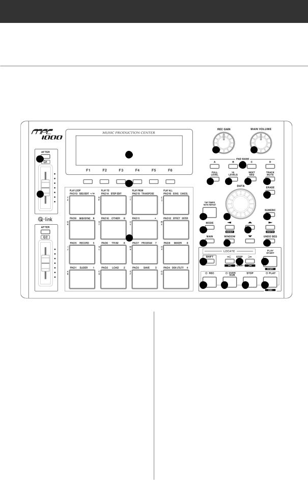
 Top Panel
24
27
25
28
26
01.[REC GAIN] knob:
It controls the recording level of the incoming signal from [RECORD IN]. It cannot control the digital input level.
2.[MAIN VOLUME] knob:
It controls the levels of [STEREO OUT] and [PHONES] (headphone).
3. PAD BANK [A] through [D] keys:
Use these keys to switch between pad banks A, B, C, D. The LED above currently selected pad bank will be lit.
4. [FULL LEVEL] key:
When turned on (LED is lit), the MPC1000 always plays back at the maximum velocity (127).
5. [16 LEVELS] key:
When turned on, you can use 16 pads to change
1 2
3
4 5 6 7
|
|
|
|
|
|
8 |
9 |
10 |
|
|
|
|
11 |
12 |
|
13 |
|
|||
14 |
15 |
|
|
|
|
16 |
|
|
|
|
|
|
|
17 |
|
|
BAR |
|
|
|
|
18 |
|
|
19 |
||
|
|
|
STEP |
|
|
|
20 |
21 |
22 |
23 |
|||
the selected pad’s velocity and tune in 16 steps. For more information, see the “16 Level function” section on page 41.
6. [NEXT SEQ] key:
This key calls up the NEXT SEQ page, where you can switch sequences with pads.
For more information, see the ”Selecting the sequence to play with pad” section on page 43.
7. [TRACK MUTE] key:
This key calls up the TRACK MUTE page where you can mute a track with pads. For more information, see the “Selecting track mute with pads” section on page 42.
8. [ERASE] key:
This key deletes event(s) within a track. You can delete events in real time on recording, or you can select the events to delete in the Erase window. For more information, see the “Erase feature” section on page 14.
MPC1000 v2 Operator’s Manual rev 1.0

3
9. [TAP TEMPO/NOTE REPEAT] key:
You can set a tempo by tapping this key to the desired tempo (TAP TEMPO feature). Also, by holding a pad while pressing this key, you can repeat a note according to the setting in T.C. (NOTE REPEAT feature). For more information, see the “Tap Tempo feature” section on page 18, and the “Note Repeat feature” section on page 17.
10. [DATA] wheel:
This changes the value of the currently selected field.
11. [NUMERIC] key:
If you press this key in any field, allowing you to enter numbers, the LED will blink and you can enter numbers using pads.
12.[MODE] key:
When you press this key (LED will blink), you can switch modes with pads.
13.[CURSOR] key: (  /
/  /
/  /
/  )
)
You can move the highlighted cursor up and down on the screen to select a field. In the value field, you can switch digits by pressing  /
/  keys, holding [SHIFT] key.
14.[MAIN] key:
Pressing this key displays MAIN mode, regardless the current mode.
15.[WINDOW] key:
Pressing this key, when the LED is lit, displays a pop up window where you can make a detailed setting of the field.
16.[UNDO SEQ] key:
When you record a sequence, the LED of this key will light up. Pressing this key, when the LED is lit, resets the system to its status before recording, and LED will be turned off.
17.[SHIFT] key:
You can use various features with a combination of another key.
18.[BAR] key: ( < / > )
You can move sequences by bar. When you press </> keys holding the [SHIFT] key, you can step through sequences according to the value of the timing correct setting.
19.[PLAY START] key:
Plays a sequence from the start if LOOP:OFF.
If LOOP:ON plays sequence from loop start. Press [SHIFT] + [PLAY START] to go to start of sequence.
20.[REC] key:
Pressing the [PLAY START] key or the [PLAY] key holding this key starts recording to a sequence. Any event that is already recorded on the track will be replaced with new events.
You can punch in by pressing the [PLAY] + [REC] key while playing back a sequence, and punch out by pressing the [REC] key during recording.
For more information, see the “Punch In/Punch Out feature” section on page 17.
21.[OVER DUB] key:
This key is basically the same as the [REC] key, but it adds new events to the current events (over dub). You can punch in by pressing the [PLAY] + [OVER DUB] keys while playing back a sequence, and punch out by pressing the [OVER DUB] key while over dubbing.
22.[STOP] key:
This key stops the play back/recording of a sequence. If you hit this key 3 times quickly, you can stop all sound playing back.
23.[PLAY] key:
This key starts the play back of a sequence from its current position. Pressing the [SHIFT] + [PLAY] keys moves to the end of the sequence.
24.Display:
This is the LCD (Liquid Crystal Display) with backlight.
25.[F1] through [F6] keys:
These keys are used to call up pages to the bottom of the display, or to execute the feature assigned to the key. The available feature depends on the currently displayed screen.
26.[PAD1] through [PAD16]:
These are the drum pads to play the internal sampler. The pressure/strength you use to hit the pad controls the level of the sound. In TRACK MUTE mode, you can select a track and, in NEXT SEQ mode, you can select a sequence with a pad. You can also use these pads to select modes or to enter letters.
27.[AFTER] key:
When you turn on this key, the information of the Q-Link slider recorded on a track replaces the current value of the slider. For more information, see page 45.
28.[Q1] and [Q2] sliders
These sliders control the sound according to the setting in the SLIDER mode. For more information, see the “Q-Link slider” section on page 44.
MPC1000 v2 Operator’s Manual rev 1.0
4 |
Chapter 1: Introduction |
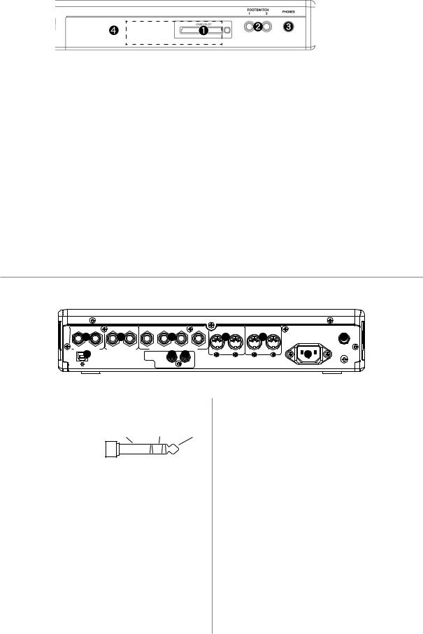
 Front Panel
01.Compact flash slot:
This is a card slot for the compact flash memory card.
02.[FOOTSWITCH 1/2] plug:
This is where you connect a foot switch. You can use a foot switch to punch in/out. For more information, see the “Foot Switch” section on page 100.
There are two types of foot switches: normal open (the contact is open when it is not pressed), and normal closed (the contact is closed when it is not pressed).
If a foot switch has been connected to the MPC1000, when you turn on the power to the MPC1000, it automatically detects the type of foot switch connected. You can use either type of foot switch.
3.[PHONES] plug:
This is a stereo phone plug to connect a set of headphones. It sends out the same signal with the [STEREO OUT] plug.
4. 2.5 inch Hard Disk drive Bay:
Internal Hard Disk drive is installed inside. (The installation is done by removing the Front Panel.) The kit-HDM10 (optional) and the 2.5 inch Hard Disk drive are needed.
 Rear Panel
RIGHT LEFT |
RIGHT LEFT |
4 |
3 |
2 |
1 |
MIDI OUT |
MIDI IN |
|
1 |
2 |
|
3 |
|
|
B 4 A |
2 5 1 |
10 |
RECORD IN |
STEREO OUT |
|
ASSIGNABLE MIX OUT |
|
|
|
||
USB 6 |
|
DIGITAL 7 |
|
8 |
|
|
9 |
|
OUT IN
01. [RECORD IN L/R] plug:
This is an analog input for recording an analog signal.
With a stereo phone |
COLD HOT |
GND |
|
plug, it can be used as |
|
balanced input. |
|
2.[STEREO OUT L/R] plug:
This is the main output .
3.[ASSIGNABLE MIX OUT 1/2/3/4] plug:
These are outputs you can use to output each pad sound separately. With external mixers or effecters, you can perform advanced mixing.
4. [MIDI OUT A/B] plug:
This is the MIDI output. Each output can send independent MIDI signals.
5. [MIDI IN 1/2] plug:
This is the MIDI input. MIDI signals from MIDI IN 1 and 2 will be merged (mixed).
6. [USB] plug (slave):
You use this plug to connect the MPC1000 to your PC and transfer data. For more information, see the “Connecting the MPC1000 to your computer” section on page 98.
7. [DIGITAL OUT] plug:
This is the coaxial digital output. It sends out the same signal as the [STEREO OUT] plug.
8. [DIGITAL IN] plug:
This is the coaxial digital input. Use this input to connect digital outputs such as a CD player and a DAT.
9. Power plug:
Plug in the AC cable here.
10.[POWER] switch:
It switches the power on/off of the unit.
MPC1000 v2 Operator’s Manual rev 1.0

5
 Connecting MPC1000 to External Audio/MIDI device
The diagram below demonstrates how you can connect the MPC1000 to an external Audio/MIDI device.
Please note that this is one example, so, when you actually connect your devices, refer to the device’s operator's manual.
Note: When you connect devices, make sure the power is turned off.
CD Player |
|
Mixer |
Amplifier |
Monitor Speaker |
Microphone |
|
|||
|
|
|||
|
|
|
|
LINE OUT
INPUT
AUDIO OUT Sound Module
MIDI IN
RIGHT LEFT |
RIGHT LEFT |
4 |
3 |
2 |
1 |
MIDI OUT |
MIDI IN |
1 |
|
|
|
|
|
|
|
B |
A |
2 |
|
RECORD IN |
STEREO OUT |
|
ASSIGNABLE MIX OUT |
|
|
|
|
||
USB |
|
DIGITAL |
|
|
|
|
|
|
|
|
|
|
OUT |
|
IN |
|
|
|
|
|
|
|
|
|
DIGITAL |
|
|
|
|
|
USB |
|
|
|
OUT |
|
|
|
|
|
PC or MAC |
|
DIGITAL |
|
CD Player |
|
|
||
|
|
|
|
|
|
||||
|
|
IN |
|
|
|
|
|||
MASTER |
|
|
|
|
|
|
|
|
|
|
|
|
|
|
|
|
|
|
|
OUT L/R |
|
|
|
|
|
|
|
|
|
|
|
|
|
|
|
|
MD Recorder |
MIDI OUT |
|
|
PHONO |
|
|
|
|
|
|
|
|
DJ Mixer |
|
|
|
|
Turn Table |
|
|
MIDI Keyboard |
|
FOOTSWITCH
1 |
2 |
PHONES |
Compact Flash
Footswitch 
Headphone
MPC1000 v2 Operator’s Manual rev 1.0

6 |
Chapter 1: Introduction |
Terminologies in MPC1000
These are the basic terminologies you need to know to operate the MPC1000:
 Sequence
Sequence is the most basic unit that you use when you create data with the MPC1000. The data from the MIDI keyboard or pads will be recorded to each track in a sequence.
A sequence has 64 tracks, each of which can hold performance data. You can create up to 99 sequences. The length of a sequence can be set from 1 bar to 999 bars. You can create a whole song with one sequence; however you can also create a song with a combination of several short sequences with the Song feature.
 Track
Track
A sequence has 64 tracks. Each track can record separate performance data. For example, you can record instruments separately on each track (ex. Piano sound in track 1, Bass on Track 2, Organ on Track 3,etc…). You can record one track at a time; however, you can play back already-recorded tracks while recording a new track. Each track has the track mute setting (whether play back the contents of the track or not). For example you record two Piano solos on Track 1 and Track4 and compare them using mute function. Performance data will be recorded on a track as a MIDI event. It does not record sounds directly on a track.
 Song
Song
With the song feature, you can play back sequences in a certain order. You can set the order and number of sequences to play back freely. This is useful when you wish to play back several songs in a row, or when you are creating a song with a combination of several sequence data.
With the MPC1000, you can create up to 20 songs. When you arrange sequences into a song, assign them to each step in the song. A step is like a “container” of sequences. A song has 250 steps.
MPC1000 v2 Operator’s Manual rev 1.0
7
 Sample
With the MPC1000, sound data that is loaded into the unit is called a sample. A sample is loaded to the MPC1000 when you record in RECORD mode, load from a memory card, or transfer from PC through USB. You can change the start/end point of a sample or set loop in TRIM mode. To play back sounds, you need to assign samples to pads in PROGRAM mode. There are 2 kinds of samples: Stereo sample (2-channel sample with left and right channels), and Mono sample (1- channel sample).
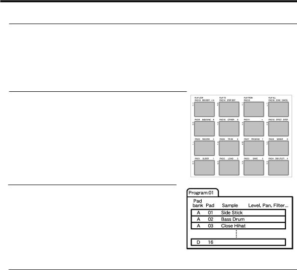
 Drum Pad
The MPC1000 has 16 pads. You can play a sample that is assigned to a pad by hitting the pad. The MPC1000 has 4 pad banks that you can assign separate samples to. You can switch those 4 pad banks using the [PAD BANK] key, so you can use up to 64 pads. To assign samples to the pads, use the PROGRAM mode. The performance of the pad can be recorded to a track in a sequence.
 Program
Once you assign samples to the pads in the PROGRAM mode, you can play those samples with the pads.Aset of 64 pads, each assigned samples, is called the Program. The program also has features that allow you to control the sound of samples, such as envelop and filter. You can make settings separately for each pad.
 Note Number
This refers to the position (note) of the MIDI note event on the keyboard. For example, the note number for “Middle C” on the piano is “60”. The lowest key on the piano is “A-1” which is note number ”21”. On a MIDI track, the MIDI keyboard performance data is recorded as a note number. On a Drum track, the note number is used to play back the sound in the internal sample. If you play the pads and recorded to a drum track, the note numbers assigned to the pad will be recorded on the track. When you play back this track, the sound assigned to the note number is played back.
MPC1000 v2 Operator’s Manual rev 1.0

8 |
Chapter 1: Introduction |
 RAM
RAM
RAM (Random Access Memory) is a space where you can load sounds or data temporarily. The MPC1000 comes with 16 MB (megabyte) of RAM that can record up to 136 seconds (monaural recording). The MB is a unit that represents the size of the memory. With the optional EXM128, you can increase your memory to 128MB.
The data loaded in the RAM will be deleted when you turn off the MPC1000. If you wish to save your recordings, you need to save on a memory card, or transfer the data to PC through USB.
 Memory Card
The MPC1000 has a 32MB compact flash memory card. Compact Flash is a memory that is called “Flash Memory” .You can save the data on the flash memory like RAM, but the data will remain after you turn off the unit. By saving the recordings in the MPC1000’s RAM on the Memory card, you can save the data after you turn off the MPC1000. Please note that the MPC1000 cannot play back the data directly from a memory card. You have to load the data from a card to RAM to play back. There are several kinds of flash memory cards, but MPC1000 uses “compact flash” memory cards.
MPC1000 v2 Operator’s Manual rev 1.0
9
Chapter 2 : Basic Operation
In this chapter, we will describe the basic operation of the MPC1000.
 MAIN Page
This is the main screen of the MPC1000, where you record and play back sequences. You can go back to this page at any time by pressing the [MAIN] key; for example, when you get lost while operating MPC1000 and want to go back to this page. You cannot go back to MAIN page by pressing [MAIN] key while processing (e.g. recording, loading/saving etc..).
 Cursor, Cursor Keys, Field, DATA Wheel
The highlighted part on the screen is called the “Cursor” (On above screen, [ ] on Main screen is highlighted).You can move the cursor on the screen using four cursor keys on the panel. Usually they move to a specific locations such as right to colon ( : ) . Those locations are called “field”, where you can make various setting, or enter values. To change the settings of a field, select the field and turn the [DATA] wheel on the panel.
This operation, selecting a field by using a cursor key and changing its settings with the [DATA] wheel, is the most basic operation of MPC1000.
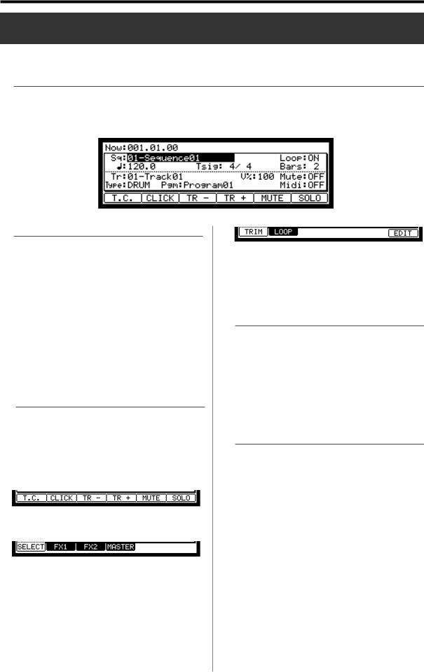
 Function Keys
Six keys (F1 to F6) aligned under the LCD (liquid crystal display) are function keys. Those keys correspond to each of the six functions that are displayed on the bottom of the LCD. Pressing each key activates its corresponding function. The function that each function key represents depends on the contents on the LCD.
When the LCD displays like this, pressing function keys starts some processing or displays windows.
When LCD displays like this, you can switch pages using function keys F1 to F4. The currently selected page is displayed with black letters on a white background. Pressing F5 and F6 keys does not make any changes.
Some pages display the page selection and processing function at the same time (see below).
In this case, use F1 and F2 for switching pages, and F6 for activating processing. You cannot use F3, F4 and F5. In this book, function keys are described something like this: “[F1] (TRIM) key”- in the bracket, it shows the function displayed on LCD.
 WINDOW key
The MPC1000 has so many functions that they cannot be displayed in one screen. For efficiency, each page only displays the most frequently used functions. If you want to make an advanced setting, press the [WINDOW] key. This opens a window for the detailed setting of the selected field. This is not available for all fields. When you select a field in which you can use the [WINDOW] key, the LED of the key is lit.
 MODE key
With the MPC1000, each function (such as recording samples, editing samples, assigning samples to each pad, editing sequence data, loading from memory cards, etc…) has a separate screen. These screens are called “modes”. For example, you will use the RECORD mode to record samples, and the TRIM mode to edit samples, the [MODE] key switches modes. By pressing the [MODE] key and hitting a pad, you can switch modes. The mode that a pad corresponds to is displayed above each pad.
MPC1000 v2 Operator’s Manual rev 1.0
10 |
Chapter 2: Basic Operation |
Setting names
The MPC1000 handles various types of data, from sound related data (such as samples and programs) to performance related data (such as sequences and tracks). These data are managed by names. In this section, you will learn how to name different data.
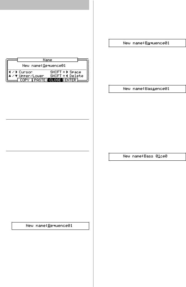
Select a field which you wish to name with the cursor and turn the DATA wheel. The Name windows will show up. In the Name windows, you can name the data.
In this window, the cursor is displayed as an underscore instead
of highlights.
You can enter the name, either by using pad or by using DATA wheel.
 Entering letters with DATA wheel
You can change letters selected with a cursor by turning DATA wheel in the Name window. Move the cursor with RIGHT/LEFT cursor key and enter letters. You can enter letters using both DATA wheel and pads.
 Entering letters with a pad
Two letters are assigned to each pad. By hitting a pad, the corresponding letter is entered. Below, we will describe how to enter “Bass 01” instead of “Sequence 01”.
01.Press the UP cursor key to make the first letter capitalized.
Pressing the UP cursor key allows you to enter a capitalized letter.
02.Hit Pad 1 twice.
Hitting Pad 1 once enters A, twice enters B. Each time you hit the pad, the letter switches between A and B.
03.Press the RIGHT cursor key and move the cursor to the right.
If you enter the next letter using a different pad, the cursor will move to the right automatically. However, when you enter the letters which are assigned to the same pad, you need to press the RIGHT cursor key to move the cursor manually. In this example, A and B are assigned to the same pad. So, you need to move the cursor manually.
04.The next letter is a lower-case letter (“ a ”), so press the DOWN cursor key.
Pressing the DOWN cursor key allows you to enter lower case letters.
05.Hit Pad 1 once.
The lower case letter “a” is entered.
06.Hit Pad 10 once.
The cursor will move to the right automatically and a lower-case letter “s” is entered.
07.Press the RIGHT cursor key to move the cursor to the right and hit the pad 10 once.
08.Press the RIGHT cursor key to move the cursor to the right and press RIGHT cursor key holding the [SHIFT] key.
The [SHIFT] + RIGHT cursor key inserts space.
09.Press the right cursor key to move the cursor one step to the right, and select “0” by turning the DATA wheel.
To enter numeric values, use the DATA wheels.
10.Press the RIGHT cursor key to move the cursor to the right, and select “1“ by turning the DATA wheel.
11.Press the RIGHT cursor key to move the cursor to the right, and press the LEFT cursor key four times holding the [SHIFT] key.
The [SHIFT] + LEFT cursor keys delete selected letters. Now “Bass 01” is entered instead of “Sequence 01”.
12.Press [F5] (ENTER) to confirm the entry and close the window.
Pressing [F4] (CANCEL) cancels the entry and closes the window. In this case, the name does not change.
MPC1000 v2 Operator’s Manual rev 1.0
11
 Other useful functions in the Name window
(Copy and Paste function)
With the copy and paste function, you can copy the letters in the “New name” field and paste to set a name to another data. This is useful when you wish to create similar names for different data.
If you press [F2] (COPY ) key when Name window is open, the letters in the “New name” field will be copied (temporarily saved). When you press [F3] (PASTE) in the Name window , those copied letters can be pasted to the “New name" field.
Entering numbers with
NUMERIC key
In the value fields such as the sample’s TRIM page, you can
enter numbers directly by using [NUMERIC] key.
01.Press the [NUMERIC] key on an available field.
The key’s LED will blink and allows you to enter numbers using the pad.
02.Enter numbers by hitting the corresponding pads.
The number indicated on the upper right corner of the pad is entered. Pad 1 through 9 corresponds number 1 to 9 and Pad 10 corresponds to number 0. When you enter the wrong number, hit Pad 16. The number is canceled and you can enter the correct number.
03.Hit Pad 12.
That confirms your entry.
When you set the Time field, you can change the unit (digit) by hitting Pad 11. In fields where you can set +/-, you can switch + and – by hitting Pad 13.
MPC1000 v2 Operator’s Manual rev 1.0
12 |
Chapter 3: Sequence feature |
Chapter 3 : Sequencer feature
The MPC1000 has a sequencer feature that allows you to record/playback your performance. With the sequencer feature, you can record the performance you created with the pads. And by playing back the recorded data, you can reproduce your performance. The actual performance will be recorded on a track within a sequence. For more information on sequences and tracks, see the “Terminologies in MPC1000” section on page 6.
The performance data you made by hitting the pads will be recorded on a track as a pad event. A track can contain other events, such as Q-Link slider information, tempo change etc… When you are using the MPC1000 with an external MIDI device, you can record the data from the external keyboard as MIDI events.
Note: Please note that Sequencer feature records only performance data (when and which pad you hit, etc… ). It does not record the actual sound.
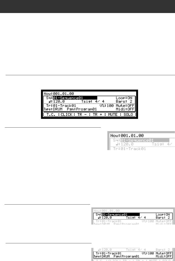
 MAIN page
This is the page where you record/playback sequences. This is the MPC1000’s main operation mode and, unlike the other pages, you can display this page just pressing the [MAIN] key at any time.
 Now field
The Now field, which is located in the upper left corner of the screen, displays the current time of the sequence. It shows the bar, beat, tick (1 beat = 96 ticks), from left to right. For example, “002.03.00” means the third beat in the second bar. A tick is a unit that divides a beat (1/4 note) into 96 parts. For example, 1 beat equals one 1/4 note (96ticks), so one 1/8 note equals the half of 1 beat, which is 48 ticks.
Below is the relationship between note and tick:
1/4 note |
= 96 ticks |
1/8 note |
= 48 ticks |
1/16 note |
= 24 ticks |
1/4 triplets |
= 64 ticks |
1/8 triplets |
= 32 ticks |
1/16 triplets |
= 16 ticks |
When you record/playback a sequence, the display updates constantly to show the current position of the sequence. You can move the cursor to the Now field to set the time manually.
 Sequence / Sq field
A Sequence is the most basic unit when you create data with the MPC1000. Performance data from the MIDI keyboard or pad can be recorded on each track within a sequence. You can select a sequence in the Sq field. An unused sequence is indicated as (unused). All the settings in the MAIN page can be set separately for each sequence.
 Track / Tr field
A sequence has 64 tracks where you can record various performance data separately. You can, for example, record Piano sounds on track 1, Bass on track 2, Organ on track 3 etc… In the Tr field, you can select a track within the se-
quence selected in the Sq field. An unused track is indicated as (unused). You can set Mute, Midi, V%, Type, and Pgm fields separately for each track.
MPC1000 v2 Operator’s Manual rev 1.0

13
Recording the performance
In this section, you will learn how to record the performance
you made with pads to tracks in a sequence.
Note: To record your performance data to a sequence, you need to load a program to the MPC1000 that you play using the pads. By default, the MPC1000 automatically loads a preset program and demo sequence when you switch it on. Here, we assume that you have already loaded a program to the MPC1000. If you have not done so, do this now by loading a program from a memory card, or by recording a sample and assigning it to a pad, etc… For more information on loading a program, see the “Loading a file” section on page 93. For more information on recording a sample, see the “recording a sample” section on page 50.
01.Press the [MAIN] key.
The [MAIN] key displays the MAIN page where you record your sequences.
02.In the Sq field, select a sequence to which you wish to record your performance.
You can select any sequence for recording a performance; but here, select a sequence that says “unused”. “Unused” indicates that the sequence is not used.
03.In the Tr field, select a track on which you wish to record your performance.
Your performance will be recorded on the track you select in the sequence. You can select any track, but here select “Tr:01”.
04.In the Pgm field, select a program you wish to play.
You can select a program in the RAM by turning the DATA wheel.
05.Hit pads to check the sounds that are assigned to the pads.
You can play back the program selected in the Pgm field.
06.Press the [PLAY START] key while holding the [REC] key.
The recording will start after 4 counts.
07.Play the pads to record your performance.
By default, the sequence is set to 2 bars. After recording for 2 bars, the MPC1000 will start playing back the recorded performance. You can add to your original performance by continuing to play the pads when the track loops. The MPC1000 automatically switches to "over dub" recording and adds to the performance.
08. You can stop overdub recording by pressing [STOP] key.
09. Press the [PLAY] key to play your recorded performance.
10.If you do not like the performance, you can start a new recording by pressing the [REC]
[PLAY START] keys.
This cancels the currently recorded performance data and starts a new recording.
11.To add to the already recorded performance, press the [PLAY START] key while holding the [OVER DUB] key.
It plays back the currently recorded performance and
you can add the new performance by hitting pads.
Tips: If you select another sequence in the Sq field, you can record a new performance separately. By playing back those sequences, you can create one whole song.
Tips: By default, the MPC1000 is set to load a demo sequence automatically when you turn it on. If you wish to remove the demo sequence and start from the scratch, see “Deleting all sequences” section on page 20.
MPC1000 v2 Operator’s Manual rev 1.0
14 |
Chapter 3: Sequence feature |
Playing back a sequence
You can play back a recorded sequence by pressing the [PLAY START] key. The sequence will be played repeatedly until you press the [STOP] key. If you press the [PLAY] key again, the MPC1000 will resume the playback from where the previous play back was stopped.
 Repeat play back of a sequence
You can play back several sequences in a series by using the Next Sequence feature. The Next Sequence feature allows you to select the next sequence to play, during playing back a sequence, so that you can play the sequences in a series.
01.In the Sq field in the MAIN page, select the sequence you wish to play first.
02.Press the [PLAY START] key to start the play back of the sequence.
03.Select the Sq field during play back, and select the next sequence to play.
Selecting a sequence in the Sq field during the playback brings up the Next field, where you can select the next sequence.
After playing back the currently selected sequence to the end, the MPC1000 will start playing back the sequence you select in the Next field. By repeating this step, you can play back several sequences continuously.
Tips: With the [NEXT SEQ] key, you can select the next sequence with a pad. For more information, see the “Selecting a sequence to play with pads” section on page 43.
Tips: In the SONG mode, you can set the order to play sequences. For more information, see the “SONG mode” section on page 37.
Other useful features for recording sequences
 Undo Sequence feature
When overdubbing sequences, you can cancel the last
recording and reset to the setting before the recording.
01.During overdubbing, press the [STOP] key to stop the overdub and press the [UNDO] key.
The LED of the [UNDO] key will be off and only the last added recording will be deleted. To restore the recording, press the [UNDO] key again to light the LED.
Note: You can use the [UNDO] key only for the last recording.
 Erase feature
You can delete a certain pad performance by using the [ERASE] key. There are two ways to use this feature: by deleting real-time during overdub, and by selecting a pad and part to delete in the ERASE window when overdub is stopped.
• Deleting in real time
01.Press the [PLAY START] key while holding the [OVER DUB] key to start overdub.
02.Hold the pad you wish to delete while holding the [ERASE] key.
From the performance data being recorded, only the section from where you press the [ERASE] key and pad and you release them will be deleted. By pressing the pad at the right timing, you can delete the performance data at a certain timing in the phrase.
• Deleting in the Erase window
Performance data will be recorded in a track as an event. In the Erase window, you can select specific events in a track to delete.
01. Press the [STOP] key to stop a sequence.
02.Press the [ERASE] key.
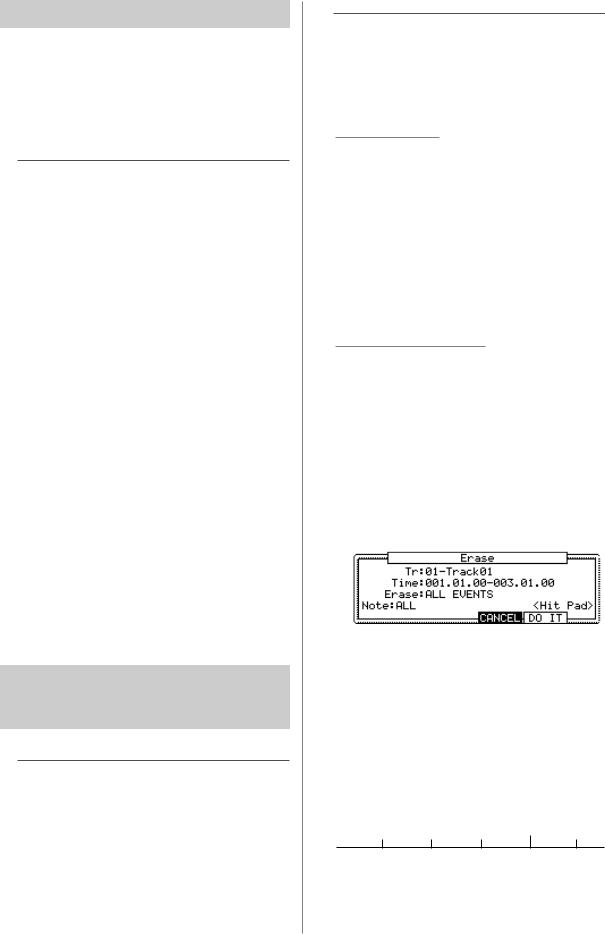
The Erase window will open up.
The Tr field displays the number and the name of the selected track. To delete all the events of the track, select “Tr : 00 - ALL TRACKS” by turning the DATA wheel to the left.
03.In the Time field, specify the area to delete events.
You will select the start and end point of the area in the Time field. For example, to delete only the event in the first bar from 2-bar sequence, set “001.01.00 - 002.01.00”. In this case, the event at 002.01.00 point will not be deleted.
If you set the end point “002.01.00” like this, the area right before the end point will be included in the area.
002.01.00
EVENT EVENT EVENT EVENT EVENT
001.04.93 001.04.94 001.04.95 |
002.01.01 |
MPC1000 v2 Operator’s Manual rev 1.0
15
04.In the Erase field, select NOTE ONLY.
Note field will open up.
05.Select the Note field.
If you wish to delete all events, leave it as ALL. To delete only events on a specific pad, hit the pad to delete. You can select several pads. If you hit a different pad by mistake, you can cancel the selection by hitting the pad again. To restart the pad selection, turn the DATA wheel to the left. The value in the Note field will be reset to ALL so that you can select pad from the beginning.
06.Press [F5] (DO IT) key.
The operation starts and the events of the selected pad within the selected area will be deleted.
Tips: When you delete events with the Erase field set to ALL EVENT, the MPC1000 will delete other events in the selected area as well as pad events. When you delete events with the Erase field set to EXCEPT Note, the MPC1000 will delete the other events other than the pad events in the selected area.
 Timing correct feature
When recording a pad performance, it is hard to play the pads to the tempo. By using the timing correct feature, you can correct the timing of the pad event you recorded by hitting pads. There are two ways to use this feature: by correcting the timing in real time during the recording, and by correcting the recorded event after the recording.
• Real time timing correction
You can correct the timing real-time during the recording.
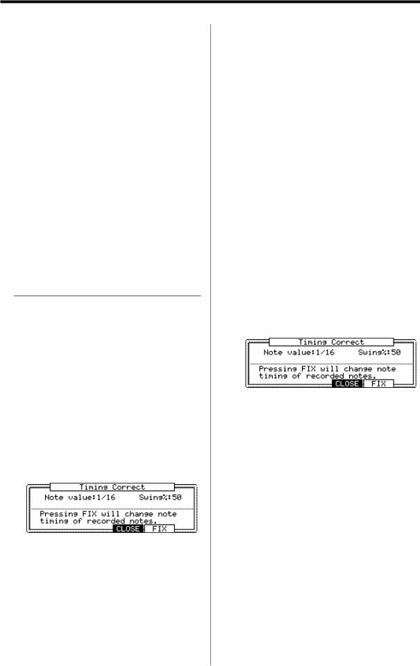
01.When a sequence is stop, press [F1] (T.C.) key in the MAIN page.
The Timing Correct window will open up.
02.In the Note value field, set the value for timing correction.
For example, if you set “1/16”, each position of the performance data will be moved to the nearest 1/16 note.
You can set the Note values as follows.
1/8 = 1/8 note, 1/8(3) = 1/8 note triplets, 1/16 = 1/16 note, 1/16(3) = 1/16 note triplets,
1/32 = 1/32 note, 1/32(3) = 1/32 note triplets, OFF = NO timing correction.
• Swing feature
You can set the swing value in the Swing% field. With the swing feature, the even numbered events set in the Note value field will be off the rhythm according to the value in the Swing% field. With this feature you can create the shuffle groove.
03.Press [F4] (CLOSE) key.
It closes the window.
Note : If you press [F5] (FIX) key, the MPC1000 will correct the timing of the recorded data.
Tips : If you press [F1] (T.C.) key during recording/playback, a small Timing Correct window will be displayed while you are holding the key. You can use the Note value field of this window to change the value for timing correction. It makes it easier to change the value during the recording.
• Correcting the timing of recorded events
You can correct the timing of recorded events.
01.When a sequence is stop, press [F1] (T.C.) key in the MAIN page.
Timing Correct window will open up.
02.In the Note value field, set the value for timing correction.
For example, if you set “1/16”, each position of the performance data will be gridded to the nearest 1/16 note.
You can set the Note values as follows:
1/8 = 1/8 note, 1/8 (3) = 1/8 note triplets, 1/16 = 1/16 note, 1/16 (3) = 1/16 note triplets, 1/32 = 1/32 note, 1/32 (3) = 1/32 note triplets, OFF = NO timing correction.
• Swing feature
You can set the swing value in the Swing% field. With the swing feature, the even numbered events set in the Note value field will be off the rhythm according to the value in the Swing% field. With this feature you can create the shuffle groove.
MPC1000 v2 Operator’s Manual rev 1.0
16 |
Chapter 3: Sequence feature |
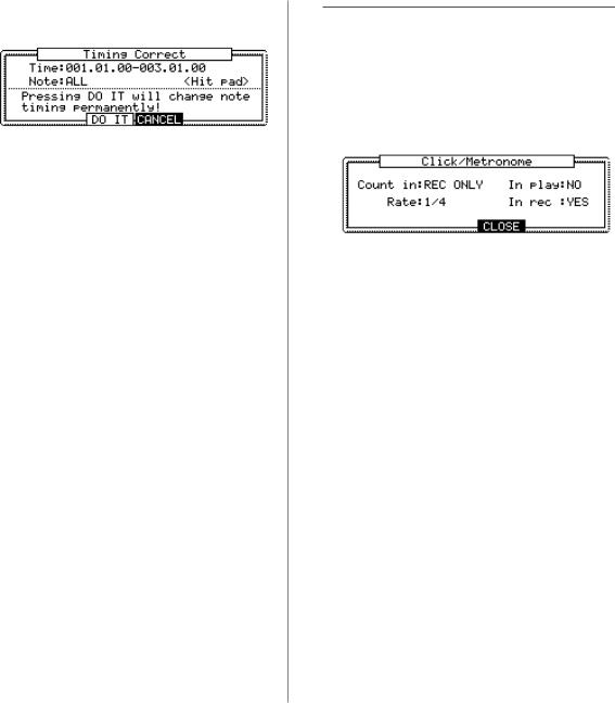
03. Press the [F5] (FIX) key.
Timing Correct window will open up.
04. In the Time field, select the area to correct the timing.
05.In the Note field, hit the pad you wish to correct the timing.
To correct the timing of all events, leave it as ALL. To correct the timing of only events on a specific pad, hit the pad. You can select several pads. If you hit a different pad by mistake, you can cancel the selection by hitting the pad again. To restart the pad selection, turn the DATAwheel to the left. The value in the Note field will be reset to ALL so that you can select pad from the beginning.
06.Press [F3] (DO IT) key.
The timing correction will start and the window will be close.
 Click/Metronome feature
In this section, you will learn about various settings for
the metronome (click sound).
01.When a sequence is in stop mode, Press [F2] (CLICK) key in the MAIN page.
Click/Metronome window will open up.
Count in field
You can set how soon the recording/playback should start after the [PLAY] or the [PLAY START] key is pressed; right after the key is pressed, or after a 1-bar count.
OFF |
Recording/playback will start right |
|
after the key is pressed without a |
|
count. |
REC ONLY |
There will be a count only for re- |
|
cording/overdub. Playback will be |
|
start without a count. |
REC+PLAY |
There will be a count for both re- |
|
cording and playback. |
Rate field
You can select the rhythm for the metronome sound. The metronome will be played with 1/4 note if you set “1/4”, and 1/8 note if you set “1/8”.
In play field
You can select this if you want the metronome sound during playback. If you select YES, you will hear the metronome sound during playback.
In rec field
You can select this if you want the metronome sound during recording/overdub. If you select NO, you will not hear the metronome sound during the recording/overdub.
MPC1000 v2 Operator’s Manual rev 1.0
17
 Note repeat feature
If you press a pad while holding the [NOTE REPEAT] key, the pad sound will be played repeatedly according to the value of the timing correct until you release the pad. You can also control its velocity by changing the strength used to press the pad. With the Note repeat feature, you can record a difficult phrase to record in real time, such as 16 beat hi hat, snare roll, etc…
01. Press the [NOTE REPEAT] key during recording / playback.
02.While holding the [NOTE REPEAT] key, press the pad to play repeatedly.
The pad’s sound will be played repeatedly according to the value of the timing correct until you release the pad. You can also control its velocity by changing the strength to press the pad.
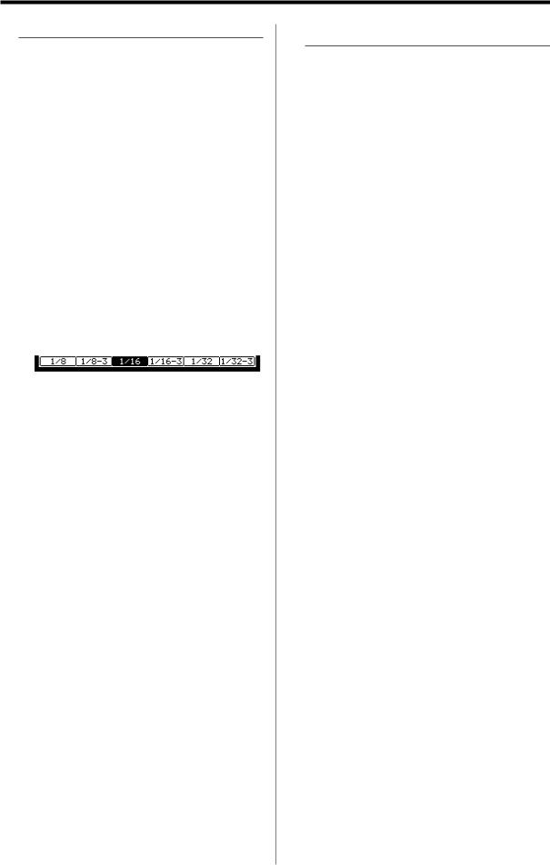
While holding down the [NOTE REPEAT] key, the bottom of display is changed as below. You can change the Timing correct value directly with pressing the [F1] through [F6] key.
The selected Timing correct value is highlighted.
Note : When you press the [F1] through [F6] key while pressing the [NOTE REPEAT] key, the other key’s LED may be lit temporarily, but it is not trouble.
Note : As the [NOTE REPEAT] key is used together with the [TAP TEMPO] key, the tempo may be changed unexpectedly during the Note Repeat function.
For preventing this accident, set OFF in the Tap average field in the “MISC.” page in the “OTHER” mode.
• Note Repeat Hold
You can also lock the “Note Repeat” feature by holding down the [NOTE REPEAT] key and then pressing the [SHIFT] key (or by holding down the [SHIFT] key and then pressing the [NOTE REPEAT] key). Pressing the [NOTE REPEAT] key again will unlock the “Note Repeat” feature.
 Punch In/Punch Out feature
You can start the recording in the middle of the sequence during the playback (“Punch In”).
You can also stop the recording in the middle of the sequence and resume the playback (“Punch Out”). This is useful when you re-record the part of the recorded sequence.
Punch In
Press the [PLAY], or the [PLAY START] key to play back a sequence. At the point where you wish to start the recording, press the [REC] key while holding the [PLAY] key. The MPC1000 will start the recording.
If you press the [OVER DUB] key and the [PLAY] key instead, the MPC1000 will start the over dubbing.
Punch Out
If you press the [REC], or the [OVER DUB] key during the recording/overdubbing, the MPC1000 will stop the recording/overdubbing and resume the playback.
MPC1000 v2 Operator’s Manual rev 1.0
18 |
Chapter 3: Sequence feature |
Detailed information on sequence feature
 Setting the length of a sequence
By default, a sequence is set to a 2-bar length, but you
can set this length between 1 to 999 bars.
01.In the MAIN page, select the Bars field.
The Bar field displays the current value.
02.Turn the DATA wheel, or press [WINDOW] key.
The Change Bars window will open up.
03.In the New bars field, select the new number of bars.
If you set a larger number than the current value, empty bars will be added at the end of the sequence. If you set a smaller number, the bars in the end of the sequence will be deleted.
04.Press [F5] (DO IT) key
That applies the new setting and closes the window.
 Setting the time signature of the sequence
By default, the time of a sequence is set to the quadruple
time (4/4), but you can change the setting.
01.In the MAIN page, select Tsig field.
The Tsig field displays the current value.
02.Turn the DATA wheel or press the [WINDOW] key.
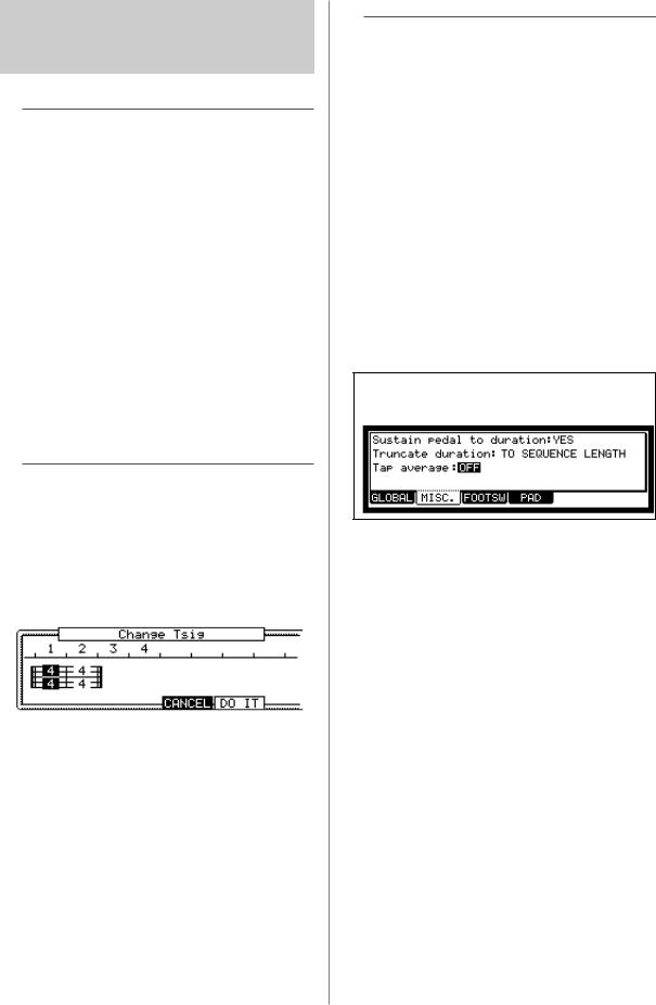
The Change Tsig window will open up.
The upper part of the screen indicates the number of bars. The currently selected time is displayed below it.
03.Select the desired time signature, and set to this.
Select the bar to change the time with the right/left cursor keys and change the time with DATA wheel. will be displayed under the time display at the bar to which you changed the setting.
04.Press [F5] (DO IT) key
That changes the time signature of the bars and closes the window.
 Setting tempo
You can set the tempo in the  (Tempo) field of the MAIN page. You can set the tempo for a sequence between 30.0 and 300.0. You can change the tempo after you create the sequence. You can also change the tempo in the sequence by inserting the tempo change event in the STEP EDIT mode.
• Tap tempo feature
You can set the tempo using the [TAP TEMPO] key as well as in the  (Tempo) field. Tap the [TAP TEMPO] key to the desired tempo. The MPC1000 will calculate the tempo starting with the timing that you tap with the [TAP TEMPO] key, and set the sequence’s tempo to that. The MPC1000 takes the average interval of 4 taps of the [TAP TEMPO] key. You can set the number of taps used to calculate the tempo in the Tap average field in the MISC. page in OTHER mode.
Note : By setting OFF in Tap average field, the Tap tempo func-
tion will be invalidity.
• Changing tempo of all sequences at one time
You can change the tempo of all sequences to the same tempo at one time. You can change the tempo of each sequence at any time after you create the sequence, but it is useful to change all the sequence at one time when you are creating one song with several sequences.
01.In the MAIN page, select  (Tempo) field and press the [WINDOW] key.
The Tempo Change window will open.
02. Press [F5] (FIX) key.
The Fix Tempo window will open.
03. In the Fix tempo field, set the tempo.
04.Press [F3] (DO IT) key.
It changes the tempo of all of the sequences to the value set in the Fix tempo field.
• About Tempo change
With the STEP RECORDING feature in the STEP EDIT mode, you can insert the tempo change even in a track, so that you can change the tempo within a sequence. When you use the tempo change feature, select the  (Tempo) field in the MAIN mode and press the
MPC1000 v2 Operator’s Manual rev 1.0

19
[WINDOW] key to open the Tempo Change window and set the Tempo change field to ON.
When you turn the tempo change feature on, the  (Tempo) field in the MAIN page will be displayed as below.
The tempo display on the left is the original tempo set for the sequence. On the right, the tempo you changed with the tempo change event will be displayed. The sequence will actually be played at the tempo in the right.
To move to the STEP EDIT mode, press [F2] (EDIT) key in the Tempo Change window.
 Setting the loop for a sequence
By default, the MPC1000 has the sequence loop feature on. It is useful when you create a short sequence. With the sequence loop feature, you can overdub a new performance while playing back a sequence repeatedly.
However, when you are working on a long song, created as a single sequence, it may be better to loop only the part of the song that needs to be changed. Also, when you wish to play freely without worrying about the bars or times, it is better to turn the loop feature off. In this section you will learn how to set the loop feature.
01.In the MAIN page, select the Loop field.
You can switch the sequence loop features ON/OFF by turning the DATA wheel.
In this field, you can only set the loop at ON/OFF. You can set the start/end points of the loop in the Loop window.
02.Press the [WINDOW] key.
The Loop window will open. The MPC1000 will repeat the part you set in the First bar and Last bar fields. If you set END in the Last bar field, the last bar of the sequence is always the end of the loop. Even if you edit a sequence and change its length, the last bar of the sequence is still the end of the loop.
The Number of bars field displays the length of the bars to loop. The Last bar field and the Number of bars field work together. Changing the value in the Last bar field also changes the value in the Number of bars field.
03.Press [F4] (CLOSE) key.
This closes the window and goes back to MAIN page.
Extending the sequence length automatically
Usually, the length of a sequence is set based on the value of the Bars field in the MAIN page. However, when you are recording/overdubbing with
the Loop field set to OFF, the length of a sequence will be extended automatically. For example, when the Bars field is set to 2, If you start recording with the loop field set to OFF, the recording will continue after second bar until you press the [STOP] key. And the number of the bar when you actually pressed the [STOP] key will be set as the new length for the sequence. This is useful when you do not know the length of the song.
Tips: When you press the [PLAY START] key when the First bar is not 1, the MPC1000 will start the playback from the bar set in the First bar field instead of from the beginning of the sequence.
 Changing the default settings
Some settings for a sequence (such as number of the bars, time, tempo, loop) are automatically set to the default setting when you create a new sequence. You can change the default settings for your convenience.
01.In the MAIN page, set the Loop field, field, Tsig field, Bars field as you like.
02.Select the Sq field and press the [WINDOW] key.
The Sequence window will open.
03. Press [F3] (USER) key.
The User Default window will open.
04.Press [F5] (DO IT) key.
The values currently set in the Loop, , Tsig, Bars field in the MAIN page will be saved as default setting. The Next time you create a new sequence, these values are applied.
 Changing the sequence name
01.In the Sq field in the MAIN page, select a sequence that you wish to change the name of.
02.Press the [WINDOW] key.
The Sequence windows will open.
03.In the Sequence name field, enter the new name.
For more information for setting the name, see the “Setting the name” section on Page 10.
04.Press [F4] (CLOSE) key.
It closes the window and goes back to MAIN page.
MPC1000 v2 Operator’s Manual rev 1.0
20 |
Chapter 3: Sequence feature |
 Changing the default name for a sequence
Usually, when you create a new sequence, the name will be set to the default name as “Sequence## (## will be the sequence number)” automatically. You can change the default name.
01. In the MAIN page, select the Sq field.
02.Press the [WINDOW] key.
The Sequence window will open.
03.In the Default name field, enter the new name.
For more information for setting the name, see the “Setting the name” section on Page 10.
04.Press [F4] (CLOSE) key.
This closes the window and goes back to the MAIN page.
 Copying a sequence
You can copy a sequence to another sequence.
01. In the Sq field in MAIN mode, select a sequence to copy.
02.Press the [WINDOW] key.
The Sequence window will open.
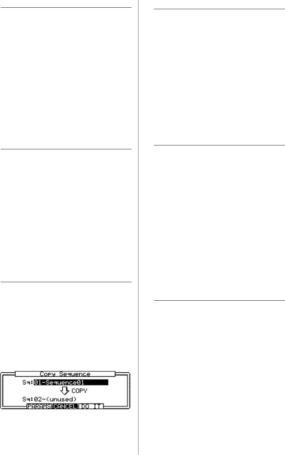
03.Press [F5] (COPY) key.
The Copy Sequence window will open.
04. In the Sq field (below), select a sequence to copy to.
05.Press [F5] (DO IT) key.
Copying the sequence will start. To cancel the operation, press the [F4] (CANCEL) key.
 Copying a sequence parameter
You can copy a sequence parameter to another sequence
01.In the Sq field in MAIN mode, select a sequence parameter to copy.
02.Press the [WINDOW] key
The Sequence window will open.
03.Press [F5] (COPY) key.
The Copy Sequence window will open.
04. In the Sq field (below), select a sequence to copy to.
05.Press [F3] (PARAMS) key
Copying the sequence parameter will start. To cancel the operation, press the [F4] (CANSEL) key.
 Deleting a sequence
You can remove a sequence from the memory of the
MPC1000.
01. In the Sq field in MAIN mode, select a sequence to delete.
02.Press the [WINDOW] key.
The Sequence window will open.
03.Press [F2] (DELETE) key.
The Delete Sequence window will open.
04.Press [F5] (DO IT) key.
That deletes the selected sequence and changes its name to “unused”.
 Deleting all sequences
You can delete all the sequence data in the memory at one time.
01.In the MAIN mode, select the Sq field and press the [WINDOW] key.
The Sequence window will open.
02.Press [F2] (DELETE) key.
The Delete Sequence window will open.
03.Press [F3] (ALL SQ) key.
The Delete ALL Sequences window will open.
04.Press [F5] (DO IT) key.
That deletes all the sequences and changes their names to “unused”.
 Handling the duration (the length of a note)
at the loop boundary
When you are recording a sequence in the loop mode, you can specify how the MPC1000 should operate when it reaches the boundary of the loop (it reaches the end of the sequence and jumps back to the beginning) while you are holding a pad.
01. Press the [MODE] key and then the [PAD 10]
(OTHER) key.
That switches to the OTHER mode.
02.Press [F2] (MISC.) key.
The MISC. page will be displayed.
MPC1000 v2 Operator’s Manual rev 1.0
 Loading...