


WARNING
To prevent fire or shock hazard, do not
expose this appliance to rain or moisture.
Operator’s Manual
WARNING!!
To prevent fire or shock hazard, do not expose this appliance to rain or moisture.
1-En
CAUTION
RISK OF ELECTRIC SHOCK
DO NOT OPEN
CAUTION: TO REDUCE THE RISK OF ELECTRIC SHOCK
DO NOT REMOVE COVER (OR BACK).
NO USER-SERVICEABLE PARTS INSIDE.
REFER SERVICING TO QUALIFIED SERVICE PERSONNEL.
THE SYMBOLS ARE RULED BY UL STANDARDS (U.S.A.)
The lightning flash with arrowhead symbol , within an equilateral triangle, is intended to alert the user to the presence of uninsulated “dangerous voltage” within the product’s enclosure; that may be of sufficient magnitude to constitute a risk of electric shock to persons.
The exclamation point within an equilateral triangle is intented to alert the user to the presence of important operating and maintenance (servicing) instructions in the literature accompanying the appliance.
5B-En
Warning
WARNING
The MPC2000 is designed to be used in a standard household environment.
Power requirements for electrical equipment vary from area to area. Please ensure that your MPC2000 meets the power requirements in your area. If in doubt, consult a qualified electrician or Akai Professional dealer.
120 VAC |
@ 60 Hz for USA and Canada |
220~240 VAC |
@ 50 Hz for Europe |
PROTECTING YOURSELF AND THE MPC2000
•Never touch the AC plug with wet hands.
•Always disconnect the MPC2000 from the power supply by pulling on the plug, not the cord.
•Allow only an Akai Professional dealer or qualified professional engineer to repair or reassemble the MPC2000. Apart from voiding the warranty, unauthorized engineers might touch live internal parts and receive a serious electrical shock.
•Do not put, or allow anyone to put any object, especially metal objects, into the MPC2000.
•Use only a household AC power supply. Never use a DC power supply.
•If water or any other liquid is spilled into or onto the MPC2000, disconnect the power, and call your dealer.
•Make sure that the unit is well-ventilated, and away from direct sunlight.
•To avoid damage to internal circuitry, as well as the external finish, keep the MPC2000 away from sources of direct heat (stoves, radiators, etc.).
•Avoid using aerosol insecticides, etc. near the MPC2000. They may damage the surface, and may ignite.
•Do not use denaturated alcohol, thinner or similar chemicals to clean the MPC2000. They will damage the finish.
•Modification of this equipment is dangerous, and can result in the functions of the MPC2000 being impaired. Never attempt to modify the equipment in any way.
•Make sure that the MPC2000 is always well-supported when in use (either in a speciallydesigned equipment rack, or a firm level surface).
•In order to assure optimum performance of your MPC2000, select the setup location carefully, and make sure the equipment is used properly. Avoid setting up the MPC2000 in the following locations:
1.In a humid or dusty environment
2.In a room with poor ventilation
3.On a surface which is not horizontal
4.Inside a vehicle such as a car, where it will be subject to vibration
5.In an extremely hot or cold environment
Page i

Warning
WARNING
THIS APPARATUS MUST BE EARTHED
IMPORTANT
This equipment is fitted with an approved non-rewireable UK mains plug.
To change the fuse in this type of plug proceed as follows:
1)Remove the fuse cover and old fuse.
2)Fit a new fuse which should be a BS1362 5 Amp A.S.T.A or BSI approved type.
3)Refit the fuse cover.
If the AC mains plug fitted to the lead supplied with this equipment is not suitable for your type of AC outlet sockets, it should be changed to an AC mains lead, complete with moulded plug, to the appropriate type. If this is not possible, the plug should be cut off and a correct one fitted to suit the AC outlet. This should be fused at 5 Amps.
If a plug without a fuse is used, the fuse at the distribution board should NOT BE GREATER than 5 Amp.
PLEASE NOTE: THE SEVERED PLUG MUST BE DESTROYED TO AVOID A POSSIBLE SHOCK HAZARD SHOULD IT BE INSERTED INTO A 13 AMP SOCKET ELSEWHERE.
The wires in this mains lead are coloured in accordance with the following code:
GREEN and YELLOW |
—EARTH |
BLUE |
—NEUTRAL |
BROWN |
—LIVE |
As the colours of the wires in the mains lead of this apparatus may not correspond with the coloured markings identifying the terminals in your plug, please proceed as follows:
The wire which is coloured GREEN and YELLOW must be connected to the terminal which is marked with the letter E or with the safety earth symbol  or coloured GREEN or coloured GREEN and YELLOW.
The wire which is coloured BLUE must be connected to the terminal which is marked with the letter N or coloured BLACK.
The wire which is coloured BROWN must be connected to the terminal which is marked with the letter L or coloured RED.
THIS APPARATUS MUST BE EARTHED
Ensure that all the terminals are securely tightened and no loose strands of wire exist.
Before replacing the plug cover, make certain the cord grip is clamped over the outer sheath of the lead and not simply over the wires.
6D-En
Page ii

Warning
VENTILATION
Do not prevent the unit's ventilation, especially by placing the unit on the soft carpet, in a narrow space, or by placing objects on the unit's chassis—top, side, or rear panels. Always keep the unit's chassis at least 10 centimeters from any other objects.
31C-En
CHANGES OR MODIFICATIONS NOT EXPRESSLY APPROYED BY THE MANUFACTURER FOR COMPLIANCE COULD VOID THE USER’S AUTHORITY TO OPERATE THE EQUIPMENT.
32-En
FCC WARNING
This equipment has been tested and found to comply with the limits for a Class B digital device pursuant to Part 15 of the FCC rules. These limits are designed to provide reasonable protection against harmful interference in a residential installation. This equipment generates, uses, and can radiate radio frequency energy and, if not installed and used in accordance with the instructions, may cause harmful interference to radio communications. However, there is no guarantee that interference will not occur in a particular installation. If this equipment does cause harmful interference to radio or television reception, which can be determined by turning the equipment off and on, the user is encouraged to try to correct the interference by one or more of the following measures:
•Reorient or relocate the receiving antenna.
•Increase the separation between the equipment and receiver.
•Connect the equipment into an outlet on a circuit different from that to which the receiver is connected.
•Consult the dealer or an experienced radio/TV technician for help.
21B-En
This digital apparatus does not exceed the Class B limits for radio noise emissions from digital apparatus set out in the Radio Interference Regulations of the Canadian Department of Communications.
27-En
COPYRIGHT NOTICE
The AKAI MPC2000 is a computer-based device, and as such contains and uses software in DISKs and ROMs. This software, and all related documentation, including this Operator’s Manual, contain proprietary information which is protected by copyright laws. All rights are reserved. No part of the software or its documentation may be copied, transferred or modified. You may not modify, adapt, translate, lease, distribute, resell for profit or create derivative works based on the software and its related documentation or any part there of without prior written consent from AKAI Electric Co. Ltd, Tokyo, Japan.
Page iii
Warranty
WARRANTY
AKAI Electric Co. Ltd. warrants its products, when purchased from an authorized “AKAI professional” dealer, to be free from defects in materials and workmanship for a period of 12 (twelve) months from the date of purchase. Warranty service is effective and available to the original purchase only, and only on completion and return of the AKAI Warranty Registration Card within 14 days of purchase.
Warranty coverage is valid for factory-authorized updates to AKAI instruments and their software, when their installation is performed by an authorized AKAI Service Center, and a properly completed Warranty Registration has been returned to your “AKAI professional” dealer.
To obtain service under this warranty, the product must, on discovery of the detect, be properly packed and shipped to the nearest AKAI Service Center. The party requesting warranty service must provide proof of original ownership and date of purchase of the product.
If the warranty is valid, AKAI will, without charge for parts or labor, either repair or replace the defective part(s). Without a valid warranty, the entire cost of the repair (parts and labor) is the responsibility of the product's owner.
AKAI warrants that it will make all necessary adjustments, repairs and replacements at no cost to the original owner within 12 (twelve) months of the purchase date if:
1)The product fails to perform its specified functions due to failure of one or more of its components.
2)The product fails to perform its specified functions due to defects in workmanship.
3)The product has been maintained and operated by the owner in strict accordance with the written instructions for proper maintenance and use as specified in this Operator's Manual.
Before purchase and use, owners should determine the suitability of the product for their intended use, and owner assumes all risk and liability whatsoever in connection therewith. AKAI shall not be liable for any injury, loss or damage, direct or consequential, arising out of use, or inability to use the product.
The warranty provides only those benefits specified, and does not cover defects or repairs needed as a result of acts beyond the control of AKAI, including but not limited to:
1)Damage caused by abuse, accident, negligence. AKAI will not cover under warranty any original factory disk damaged or destroyed as a result of the owner's mishandling.
2)Damage caused by any tampering, alteration or modification of the product: operating software, mechanical or electronic components.
3)Damage caused by failure to maintain and operate the product in strict accordance with the written instructions for proper maintenance and use as specified in this Operator's Manual.
4)Damage caused by repairs or attempted repairs by unauthorized persons.
5)Damage caused by fire, smoke, falling objects, water or other liquids, or natural events such as rain, floods, earthquakes, lightning, tornadoes, storms, etc.
6)Damage caused by operation on improper voltages.
IMPORTANT NOTE: This warranty becomes void if the product or its software is electronically modified, altered or tampered with in any way.
AKAI shall not be liable for costs involved in packing or preparing the product for shipping, with regard to time, labor, or materials, shipping or freight costs, or time or expense involved in transporting the product to and from AKAI Authorized Service Center or Authorized Dealer.
AKAI will not cover under warranty an apparent malfunction that is determined to be user error, or owner's inability to use the product.
THE DURATION OF ANY OTHER WARRANTIES, WHETHER IMPLIED OR EXPRESS, INCLUDING BUT NOT LIMITED TO THE IMPLIED CONDITION OF MERCHANTABILITY, IS LIMITED TO THE DURATION OF THE EXPRESS WARRANTY HEREIN.
AKAI hereby excludes incidental or consequential damages, including but not limited to:
1)Loss of time.
2)Inconvenience
3)Delay in performance of the Warranty.
4)The loss of use of the product.
5)Commercial loss.
6)Breach of any express or implied warranty, including the Implied Warranty of Merchantability, applicable to this product.
Page iv

Contents
Table of Contents |
|
Chapter 1: Introduction ............................................................................................... |
1 |
Features .............................................................................................................. |
2 |
Panel Descriptions ............................................................................................. |
4 |
Front Panel ............................................................................................ |
4 |
Rear Panel .............................................................................................. |
7 |
Handling Floppy Disks ...................................................................................... |
8 |
The Disk Drive ....................................................................................... |
8 |
Taking care of your Disks ...................................................................... |
9 |
Chapter 2: The Basics ............................................................................................... |
11 |
Hooking Up Your System ................................................................................ |
12 |
The Terms Used in MPC2000 ......................................................................... |
13 |
Sequence................................................................................... |
13 |
Track ........................................................................................ |
13 |
Song .......................................................................................... |
14 |
Sound ........................................................................................ |
14 |
Drum Pads ............................................................................... |
14 |
Note Number............................................................................ |
14 |
Program .................................................................................... |
15 |
Operating the Front Panel and Screen ........................................................... |
16 |
The Cursor, Cursor Keys, Data Fields ................................... |
16 |
The Numeric Keypad and DATA Wheel................................. |
16 |
The Function Keys ................................................................... |
17 |
Basic Functions ................................................................................................ |
18 |
Loading the Operating System ........................................................... |
18 |
Loading and Playing Programs ........................................................... |
18 |
Playing the Drum Pads, the PAD BANK, & FULL LEVEL Keys .... |
19 |
Selecting Programs .............................................................................. |
20 |
The NOTE VARIATION Slider, ASSIGN and AFTER keys ............. |
20 |
The ASSIGN Key ..................................................................... |
21 |
The AFTER key ....................................................................... |
22 |
The 16 LEVELS key ............................................................................ |
23 |
Chapter 3: Recording Sequences ............................................................................. |
25 |
How Sequences are Organized ........................................................................ |
26 |
Bar.Beat.Tick ........................................................................... |
27 |
Examples of Sequence Recordings .................................................................. |
28 |
Example 1: Recording a Drum Pad Performance .................. |
28 |
Example 2: Recording a Loop .................................................. |
30 |
Example 3: Multi-track Recording.......................................... |
32 |
The MAIN SCREEN ........................................................................................ |
34 |
Selecting a Sequence ........................................................................... |
34 |
Next sequence function ........................................................... |
34 |
Renaming a Sequence ............................................................. |
35 |
Deleting a Sequence ................................................................ |
35 |
Copying a Sequence ................................................................. |
36 |
Page v
Contents
Setting the Tempo ................................................................................ |
37 |
Tempo Change Window ........................................................... |
37 |
Entering and Modifying a Tempo Change ............................. |
38 |
Selecting a Tempo Source .................................................................... |
39 |
Setting the Time Correct (Quantization) ............................................ |
40 |
Setting the Beat ................................................................................... |
41 |
Setting the Number of Bars ................................................................ |
42 |
Setting the Loop ................................................................................... |
44 |
Setting the Count ................................................................................. |
45 |
Selecting a Track ................................................................................. |
46 |
Renaming a Track ................................................................... |
46 |
Deleting a Track ...................................................................... |
47 |
Copying a Track ....................................................................... |
47 |
Turning the Track ON or OFF ............................................................ |
48 |
Setting the Track Type ........................................................................ |
48 |
Setting the TrackÕs MIDI Channel...................................................... |
49 |
Settings for MIDI Reception ................................................... |
49 |
MIDI Filter Function ............................................................... |
51 |
Sending the All Note Off ..................................................................... |
51 |
Multiple Track Real-time Recording .................................................. |
52 |
Editing the Velocity ............................................................................. |
53 |
Setting the Program Change Transfer ............................................... |
54 |
Locating with the DATA Wheel .......................................................... |
55 |
Units Used to Locate a Point .................................................. |
55 |
The Main Screen Function Keys ......................................................... |
56 |
The Play/Record Keys and the Locate Keys ................................................... |
57 |
The AUTO PUNCH Function .......................................................................... |
59 |
Chapter 4: Editing Sequences .................................................................................. |
61 |
Overview ........................................................................................................... |
62 |
Erasing Data with the ERASE Key ................................................................ |
62 |
Erasing a Note in Real Time ................................................... |
62 |
Using the ERASE Page to Erase Data ................................... |
62 |
Step Editing ...................................................................................................... |
64 |
Step Editing Screen ............................................................................. |
64 |
The Event Display ................................................................... |
66 |
Operating the List Display...................................................... |
66 |
Selecting and Editing Multiple Events .................................. |
67 |
Copying an Event .................................................................... |
68 |
Deleting an Event .................................................................... |
68 |
Pasting an Event ..................................................................... |
68 |
Inserting an Event ................................................................... |
68 |
Step Recording ..................................................................................... |
69 |
The Editing Screen........................................................................................... |
70 |
Copying an Event .................................................................... |
70 |
Copying by Bar ........................................................................ |
72 |
Rearranging the tracks ........................................................... |
73 |
Transposing a Track ................................................................ |
74 |
Sequence Preferences .............................................................. |
75 |
Page vi
Contents
Chapter 5: Song Mode ............................................................................................... |
77 |
Overview ........................................................................................................... |
78 |
Song Mode ........................................................................................................ |
79 |
Selecting a Song ................................................................................... |
79 |
Renaming a Song ..................................................................... |
79 |
Deleting a Song ........................................................................ |
80 |
Copying a Song ........................................................................ |
81 |
Setting the Tempo ................................................................................ |
82 |
Setting the Loop ................................................................................... |
83 |
Creating a Song.................................................................................... |
84 |
Selecting a Step and Changing a Sequence ....................................... |
85 |
Repeating a Sequence .......................................................................... |
85 |
Deleting a Step ..................................................................................... |
86 |
Inserting a Step ................................................................................... |
86 |
Setting the Locate Point ...................................................................... |
87 |
Converting a Song to a Sequence ........................................................ |
88 |
Chapter 6: Creating and Editing Programs ............................................................. |
89 |
What Are Programs? ........................................................................................ |
90 |
Creating a program.............................................................................. |
92 |
Selecting a Program and Assigning a Sound .................................................. |
93 |
Selecting Programs .............................................................................. |
93 |
Renaming Programs ................................................................ |
94 |
Deleting a Program ................................................................. |
94 |
Newly Creating Programs ....................................................... |
95 |
Copying Programs ................................................................... |
95 |
Assigning Notes to DRUMS PAD ....................................................... |
96 |
The Pad Assign Mode and Initialize ................................................... |
97 |
Assigning Sounds to Notes .................................................................. |
98 |
The Program Sound Generation Mode ............................................... |
98 |
Editing Note Parameters ............................................................................... |
100 |
Selecting Programs ............................................................................ |
100 |
Selecting Notes................................................................................... |
100 |
Copying the Note Parameter ................................................ |
101 |
Setting the Envelope.......................................................................... |
101 |
Setting the Filter ............................................................................... |
103 |
Setting the Pitch ................................................................................ |
104 |
Setting the Voice Overlap .................................................................. |
105 |
The MIDI Settings of the Sampler .................................................... |
106 |
Chapter 7: Mixer Functions ..................................................................................... |
107 |
Stereo Output Mixer ...................................................................................... |
108 |
Setting the Volume ............................................................................ |
108 |
Setting the Pan .................................................................................. |
109 |
Setting the Volume or Pan Together ................................................ |
109 |
Setting the Para Out and Effect Send (Option)............................................ |
110 |
Assigning Para Out............................................................................ |
110 |
Setting the Send Level ...................................................................... |
111 |
Setting the Para Out and Send Level Together ............................... |
111 |
Page vii
Contents
Setting the Volume or Pan for Each Note .................................................... |
112 |
Setting Up the Mixer ..................................................................................... |
113 |
Setting the Effects .......................................................................................... |
114 |
Chapter 8: Creating and Editing Sounds ............................................................... |
115 |
Sampling a New Sound .................................................................................. |
116 |
Editing a Sound .............................................................................................. |
121 |
Selecting a Sound ............................................................................... |
121 |
Renaming or Displaying the Specification of the Sound ..... |
121 |
Deleting a Sound ................................................................... |
122 |
Copying a Sound .................................................................... |
122 |
TRIM Mode ........................................................................................ |
123 |
Deleting Unnecessary Samples ............................................ |
124 |
Finely Adjusting the Start Point .......................................... |
124 |
Finely Adjusting the End Point ............................................ |
125 |
LOOP Mode ........................................................................................ |
126 |
Finely Adjusting the Loop Point ........................................... |
127 |
znEDIT Mode ..................................................................................... |
128 |
Finely Adjusting the Start Point of a Zone .......................... |
130 |
Finely Adjusting the End Point ............................................ |
131 |
Setting the Sound Parameters .......................................................... |
132 |
Beat Loop Function ............................................................... |
133 |
Chapter 9: Disk Operation ....................................................................................... |
135 |
Overview ......................................................................................................... |
136 |
The Device: Field ............................................................................... |
136 |
The Device Icons ................................................................................ |
136 |
Before Proceeding to Use a Floppy Disk........................................... |
137 |
Formatting a Disk .......................................................................................... |
138 |
Formatting a Floppy Disk ................................................................. |
138 |
Formatting a SCSI Drive .................................................................. |
139 |
Saving the Data.............................................................................................. |
140 |
Saving Across Multiple Floppy Disks ............................................... |
144 |
Copying a System Disk .................................................................................. |
145 |
Starting the MPC2000 from a SCSI Drive ....................................... |
146 |
The Auto-load Functions of the .APS and .ALL Files ...................... |
146 |
Loading Files .................................................................................................. |
147 |
Deleting a File from the Disk ........................................................................ |
152 |
Chapter 10: MIDI/SYNC Mode, OTHER Mode ........................................................ |
153 |
MIDI/SYNC Mode .......................................................................................... |
154 |
Synchronizing the MPC2000 with Other Sequencers ..................... |
154 |
Synchronizing Another Sequencer or MTR to the MPC2000 .......... |
156 |
OTHER Mode ................................................................................................. |
158 |
OTHERS Screen ................................................................................ |
158 |
INIT Screen ........................................................................................ |
159 |
VER. Screen ....................................................................................... |
159 |
Page viii
Contents
Appendix ................................................................................................................... |
161 |
Notes on Using SCSI Drives .......................................................................... |
162 |
Connecting an External SCSI Drive ................................................. |
162 |
SCSI Cables ........................................................................................ |
162 |
SCSI ID............................................................................................... |
163 |
Termination........................................................................................ |
163 |
Cable Length ...................................................................................... |
163 |
Installing the OptionsÑTo Service Technicians .......................................... |
164 |
Location of MPC2000 Option Board ..................................... |
164 |
To remove the cover: .......................................................................... |
165 |
To remove the operation panel: ......................................................... |
165 |
Installing Memory Expansion ........................................................... |
166 |
Technical Specifications ................................................................................. |
167 |
The MIDI Implementation Charts ................................................................ |
169 |
Page ix

Chapter 1
Introduction

Chapter 1: Introduction
Features
The following is a summary of some of the advanced features of the
MPC2000.
General
¥Large 248 x 60 dot LCD display with graphics.
¥6 function keys under the LCD display provide various functions on each page.
¥Built-in 1.44 megabyte floppy disk drive to store both sequence and sound data.
¥By pressing the OPEN WINDOW key at the parameter you want to edit, you are allowed to make more detailed parameter settings. It is not necessary to switch between different modes as in the case of conventional devices to make detail settings.
¥Built-in SCSI interface for storing data to external hard disk.
Sampler
¥16-bit, 44.1kHz stereo sampling.
¥High capacity sound memory: 2 megabytes standard (22 seconds mono or 11 seconds stereo), expandable to 32 megabytes with SIMM memory.
¥Digital sampling input for direct recording from digital sources with IB-M208P (optional) board.
¥128 sounds (samples) may be held in memory at one time.
¥32 simultaneous playback voices.
¥The envelope or filter can be set for each sound.
¥Optional multi-effects generator EB16* for versatile effects.
¥Sample files may be loaded from Akai S1000 and S3000 disks.
¥IB-M208P (optional) enables you to mix and output internal sampler sounds from 8 individual outputs.
¥A maximum of 24 programs (sound assignments and sound parameter settings) can be created.
¥A selection between polyphonic (multiple sounds are overlaid when the same sound is played continuously) or mono (the second sound silences the first).
¥It is possible to stop the playing of a sound with another sound. This is used to simulate the open close effect of the hi hat.
¥It is possible to copy a part of a sound as a separate sound or paste a sound to a section of a sound. It is also possible to mute or reverse part of a sound.
¥One MIDI note can play three sounds. The sounds can be played simultaneously, switched by velocity, or with the NOTE VARIATION slider.
¥Loop settings can be made to a sound.
¥The velocity can change the playback pitch..
¥When phrase sampling, it is possible to calculate the tempo of the phrase from the length of the sound loop.
¥Since the sound wave patterns are displayed, it is possible to edit the sound while watching the wave pattern. It is also possible to zoom the wave pattern.
Page 2
Chapter 1: Introduction
Sequencer
¥Loop recording function enables quick recording by looping short phrases.
¥10,000 note sequencer memory capacity. (1NOTE VARIATION = 2NOTE)
¥99 sequences may be held in memory at once. Each sequence contains 64 individual tracks,
¥2 independent MIDI output ports permit 32 simultaneous MIDI output channels.
¥2 mergeable MIDI inputs.
¥The optional SMPTE boards* enable synchronization with SMPTE time codes.
¥MTC (MIDI time code), MMC (MIDI machine control) compatible.
¥Data can be exported to or imported from standard MIDI files.
¥Step edit function enables you to edit individual events.
¥The velocity of each track can easily be modified.
¥It is possible to record to 16 MIDI channels at one time.
¥Tap Tempo feature allows the playback tempo to be set by tapping a key in the time of 1/4-notes.
¥Programmable tempo changes in mid-sequence or mid-song are supported.
¥Auto Punch feature enables you to punch in or punch out automatically in the designated sequence.
¥Swing feature enables you to add a swing-feel to the rhythm.
¥16 velocityand pressure-sensitive front panel drum pads and 4 pad banks provide a total of 64 pad/bank combinations.
¥The NOTE VARIATION slider controls the decay or filter value of the sound in real time.
¥Since it is possible to convert MIDI sustain pedal data to note duration data, you can place sustain effects independently from the note data within a track.
¥The note repeat function and the after touch function pads enable you to easily enter drum rolls and hi-hat beats.
¥The UNDO SEQ key enables you to undo sequence recordings or edits.
* Not supported by V1.0 version software.
Page 3

Chapter 1: Introduction
Panel Descriptions
Front Panel
INTEGRATED RHYTHM MACHINE
16 BIT DRUM SAMPLER / MIDI SEQUENCER
MAIN VOLUME
1 |
|
|
|
|
|
|
3 |
|
|
|
|
MIN |
MAX |
|
|
|
|
|
|
|
|
|
REC GAIN |
|
F 1 |
F 2 |
F 3 |
F 4 |
F 5 |
F 6 |
|
|
|
|
|
|
|
||||||
2 |
|
|
|
F 1 |
F 2 |
F 3 |
F 4 |
F 5 |
F 6 |
|
|
|
|
4 |
|
|
|
|
|
|
|
|
MIN |
MAX |
|
|
|
|
|
|
|
|
|
|
|
|
MAIN SCREEN |
|
OPEN WINDOW |
|
|
||
|
7 |
8 |
9 |
6 |
|
|
|
7 |
|
|
|
MIXER |
OTHER |
MIDI/SYNC |
|
DATA |
DIGIT |
|
|
|
|
|
|
|
|
|
|
|
|
|||
|
4 |
5 |
6 |
|
|
|
|
|
|
|
5 |
SAMPLE |
TRIM |
PROGRAM |
|
|
|
|
|
|
|
1 |
2 |
3 |
|
|
8 |
9 |
|
|
||
|
SONG |
PUNCH |
DISK |
|
|
|
|
|||
|
SHIFT |
0 |
ENTER |
|
|
|
|
|
|
|
|
NOTE |
TAP TEMPO |
|
|
|
|
|
|
||
VARIATION |
|
CURSOR |
|
|
|
|||||
|
|
NOTE REPEAT |
|
|
|
|
||||
0AFTER |
|
|
|
|
|
|
||||
B |
|
|
|
|
E |
|
|
|||
|
|
|
|
|
|
|
|
|||
|
ASSIGN |
|
|
|
|
|
A |
B |
||
|
|
UNDO SEQ |
|
|
|
|
|
|||
|
|
ERASE |
|
|
|
|
C |
D |
||
|
|
|
|
|
|
|
|
|||
|
|
|
|
|
|
|
|
|
||
|
|
C |
|
D |
|
|
|
|
PAD BANK |
|
|
|
|
|
|
LOCATE |
|
|
|
N |
|
|
|
|
STEP |
|
GO TO |
|
BAR |
|
|
A/a |
|
|
|
|
|
|
FULL LEVEL |
||||
|
|
|
F |
G |
|
|
H |
|
||
|
|
|
|
|
|
O |
|
|||
|
|
|
EVENT |
|
|
|
START |
END |
|
|
|
|
REC |
|
OVER |
STOP |
|
PLAY |
PLAY |
|
16 LEVELS |
|
|
|
DUB |
|
START |
|
|
|||
|
|
|
|
|
|
|
P |
|
||
|
A |
|
|
|
|
|
|
|
|
|
|
|
|
|
|
|
|
|
|
SPACE |
|
|
|
I |
|
J |
K |
|
L |
M |
|
|
R
MIDI PRODUCTION CENTER
Q
DRUMS
PAD 13 |
YZ |
PAD 14 |
& # |
PAD 15 |
- ! |
PAD 16 |
( ) |
PAD 9 |
QR |
PAD 10 |
ST |
PAD 11 |
UV |
PAD 12 |
WX |
PAD 5 |
I J |
PAD 6 |
KL |
PAD 7 |
MN |
PAD 8 |
OP |
PAD 1 |
AB |
PAD 2 |
CD |
PAD 3 |
EF |
PAD 4 |
GH |
1 MAIN VOLUME knob
This adjusts the volume of the STEREO OUT and PHONES. However, this does not adjust the volume of the optional Òassignable mix out.Ó
2 REC GAIN knob
This adjusts the level of the sound coming from RECORD IN during a sampling.
3 LCD
This 248 x 60 dot display enable graphical display.
4 Function key
This key executes the function shown on the very bottom of the display. The function surrounded by a rectangular frame  will be executed.
  indicates the currently selected page. The reversed display
  indicates that you can jump to that page by pressing the corresponding key.
Page 4
5 Numeric Pad / Mode key
This allows you to directly enter numeric data. Enter numbers with this key to a selected numeric field and press the ENTER key. If you are entering numbers with decimal value, enter the number ignoring the decimal point. (In the case of 120.5, enter 1205.) If you have made a mistake, it is possible to cancel by pressing the SHIFT key before the ENTER key. If you operate the CURSOR key, DATA wheel, or MAIN SCREEN key while you are entering with the numeric pad, the input is canceled and the data returns to the status before entry has been made. By pressing the numeric pad while holding the SHIFT key, the key functions as a Mode key and allows you to enter the mode indicated under the numeric pad key.
6 MAIN SCREEN key
This allows you to return from any page to the MAIN screen (initial screen). The MAIN screen is the basic screen used to record or play back a sequence.
7 OPEN WINDOW key
This displays the pages which allow you to set the details of the selected field.
8 DATA wheel
This allows you to change the numbers or data of the selected field. The data variably increases by rotating the wheel quickly. Also, rotate the DATA wheel while holding down the SHIFT key to set the contrast of the LCD. It is possible to change this regardless of the displayed mode.
9 DIGIT wheel
This allows you to select the digit you want to change when you are changing long digit numbers such as in the case of sample editing.
0 AFTER key
Normally, the NOTE VARIATION slider effect is valid when the drum pad is played or when the drum pad performance is recorded to a sequence. However, by turning this key on, it is possible to execute the NOTE VARIATION slider effect while the sequence is playing. This key also needs to be on when you are over dubbing only the NOTE VARIATION slider effect.
Press this key while holding down the SHIFT key to display the screen and set the parameter you want to change.
Chapter 1: Introduction
A NOTE VARIATION slider
This enables you to change the parameter of the preset internal sound source in real time. Assign the parameters in the screen that appears by pressing the AFTER key while holding down the SHIFT key.
B TAP TEMPO / NOTE REPEAT key
This allows a sequence to play at the tempo set by hitting the key.
Hold this key and press DRUMS PAD to successively play to the beat set at Timing on the MAIN screen. For example, if the Timing is set at 1/8, you can play the hi-hat at an eight beat by holding this key and pressing the DRUMS PAD assigned to the hi-hat. You can also press the DRUMS PAD harder for louder sounds or softer for softer sounds.
C UNDO SEQ key
When you record and stop a sequence the light above this key will turn on. It is possible to return to sequence back to the state before recording by pressing the key and turning off the light. If the key is pressed again, the light will turn on and the state will return to the condition after the last recording. This is convenient to compare the recording with the previous, or to undo a poor recording. You can only use the UNDO SEQ key when you are recording or editing a sequence. You cannot use this key when you are editing a program or sound. The usage of the UNDO SEQ is also limited to the time just after a recording or edit. If you move to another mode or function screen, the UNDO SEQ will be disabled.
D ERASE key
This is used to erase data on the selected track. By holding this key and pressing the DRUMS PAD of the sound you want to erase while dubbing over a sequence, you can erase the data as long as the PAD is pressed. In addition to drum tracks, you can erase the notes on a track of an external MIDI device by holding this key and pressing the note that needs to be erased on the MIDI keyboard.
The ERASE page will appear if you press this key while the sequence is not playing. This allows you to erase specific notes or lengths of data.
Page 5
Chapter 1: Introduction
E CURSOR key
This allows you to select the parameter field you want to edit. The currently selected field will be reverse displayed.
F STEP < / > key
This locates the sequence point back and forth one step at a time. The step is set in Timing on the MAIN screen. When the Timing is OFF, you can move the locate by a clock. Press this key while holding GO TO key to locate each even on a track.
G GO TO key
This key displays the locate page. By pressing the numeric pad keys 1 to 9, you can locate recorded points. Pick a point to record and display the Locate window by pressing the GO TO key and press STORE[F5]. By pressing any numeric key, you can record a locate point.
H BAR << / >> key
This locates the sequence point by bars. Holding the GO TO key, press this key to locate the start or end point of the selected track.
I REC key
While holding this key, press the PLAY key or the PLAY START key to begin the sequence recording. If there is data on the track, it will be erased by the new recording.
J OVER DUB key
While holding this key, press the PLAY key or the PLAY START key to begin the sequence recording. The new recording is dubbed over the data on the track.
K STOP key
This stops the playback or recording of a sequence.
L PLAY key
This starts the sequence from the current point (ÒNow:Ó on the MAIN screen). It is also possible to start the sequence from the point where it had stopped or select ÒNow:Ó with the CURSOR key and set the point with the DATA wheel.
M PLAY START key
This starts the sequence at the beginning.
N PAD BANK key
This switches between the 16 DRUMS PAD. There are four banks from A to D and it is possible to use 64 different sounds by switching the banks. The light is on over the key of the currently selected bank.
O FULL LEVEL key
When this key is pressed and the light is on, regardless of how hard the DRUMS PAD is hit the sound will always be generated at full velocity.
P 16 LEVELS key
The allows you to play a sound in 16 parameter levels of velocity, tone, attack, decay, or filter.
Q DRUMS PAD
This plays back other sounds including the drum within the memory. This corresponds to velocity, allowing you to change the velocity with the attack on the PAD. BY switching between the 4 banks with the PAD BANK key, it is possible to assign 64 different sounds.
R FLOPPY DISK DRIVE
This is a floppy disk drive used to load or save sound data, sequence data or the operating system. Both 2HD and 2DD floppy disks can be used.
Page 6
Chapter 1: Introduction
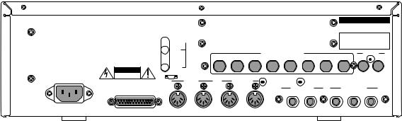
Rear Panel
WARNING TO REDUCE THE RISK OF FIRE
OR ELECTRIC SHOCK, DO NOT EXPOSE
THIS PRODUCT TO RAIN OR MOISTURE.
WARNING : SHOCK HAZARD-DO NOT OPEN!
AVIS : RISQUE DE CHOC ELECTRIQUE-NE PAS OUVRIR!
VORSICHT : BERÜHRUNGSGEFAHR-NICHT ÖFFNEN !
POWER
S
ON 
 OFF
OFF
T
CAUTION
RISK OF ELECTRIC SHOCK
DO NOT OPEN
U
SCSI
 V
V
SMPTE
IN
OUT
MIDI IN
1
Y
S POWER
This is the ON/OFF power switch.
T AC in
This is used to connect to a power source.
U SCSI
This is a 25-pin SCSI interface. This connects a hard disk drive to load or save data.
V SMPTE IN/OUT (option)
This is the SMPTE TIME CODE IN/OUT jack used to play in sync with a tape.
W ASSIGNABLE MIX OUT (option)
This allows you to set separate outputs for each sound. By using an external mixer or effecter, this enables you to conduct advanced mixing.
X DIGITAL IN/OUT (option)
This allows you to sample data directly from an audio CD or DAT. It is also possible to record the entire digital data from this outlet to a hard disk recorder or DAT such as the AKAIDR4 or DR8.
|
|
|
|
|
|
|
MODEL NUMBER MPC 2000 |
||
THIS DEVICE COMPLIES WITH PART 15 OF THE |
|
|
|
AKAI ELECTRIC CO., LTD. |
|||||
FCC RULES. OPERATION IS SUBJECT TO THE |
|
|
|
|
|||||
FOLLOWING TWO CONDITIONS :(1) THIS DEVICE |
|
|
|
MADE IN CHINA |
|||||
MAY NOT CAUSE HARMFUL INTERFERENCE, |
|
|
|
|
|
|
|
||
AND (2) THIS DEVICE MUST ACCEPT ANY |
|
|
|
|
|
|
|
||
INTERFERENCE RECEIVED, |
|
W |
|
|
|
|
|
||
INCLUDING INTERFERENCE THAT MAY CAUSE |
|
|
|
|
|
|
|||
UNDESIRED OPERATION. |
|
|
|
|
|
|
|
|
|
|
|
ASSIGNABLE MIX OUT |
|
8 |
DIGITAL |
||||
1 |
2 |
3 |
4 |
5 |
6 |
7 |
IN |
OUT |
|
|
MIDI |
OUT |
|
|
|
|
|
|
X |
|
|
|
|
|
|
|
|
||
2 |
A |
B |
|
RECORD IN |
|
STEREO OUT |
|||
|
|
|
|
LEFT |
RIGHT |
LEFT |
RIGHT |
|
PHONES |
|
Z |
|
|
[ |
|
\ |
|
] |
|
Y MIDI IN
This receives MIDI signals. It is possible to merge 1 and 2.
Z MIDI OUT
This sends MIDI signals. Since A and B are independent, it is possible to handle a total of 32 MIDI channels.
[ RECORD IN
This is the input jack used for sampling. This stereo phone jack enables you to change the balance of the input.
\ STEREO OUT LEFT/RIGHT
This is the main output jack.
] STEREO OUT PHONES
This is connected to a stereo phone headset. The same sound is output to STEREO OUT LEFT and RIGHT.
Page 7

Chapter 1: Introduction
Handling Floppy Disks
The Disk Drive
The 3.5 inch floppy disk drive will accept high density and low density disks.
Disks are inserted into the drive thus:
DISK ACTIVITY LED |
|
|
|
|
|
|
|
DISK EJECT BUTTON |
|
|
|
|
|
|
|
||
|
|
|
|
|
|
|
|
|
|
|
|
|
|
|
|
|
|
|
|
|
|
|
|
|
|
|
|
|
|
|
|
|
|
|
|
WRITE PROTECT TAB |
HIGH DENSITY |
|
DETECTION TAB |
The label should be facing upwards when it is inserted (actually, it is physically impossible to insert disks the wrong way round without using an extreme amount of brute force!).
To eject the disk, simply press the DISK EJECT button. When a disk is loading, saving or formatting, the DISK ACTIVITY LED will be lit.
As a result, it is vital that you save your work to disk before turning the power off otherwise you will lose your work and, unless previously saved or backed up, it will be gone for ever. In fact, it is a good idea to regularly save your work as you are working. All good computer users do this and it prevents the accidental loss of data should power be accidentally removed from the instrument. This also serves as a form of ÔundoÕ - if you make some kind of mistake in your programming and editing and canÕt fix it, you can load the last level of editing back into the sampler. It may be a bit tedious to keep stopping every now and then to save your work but it is better than losing some valuable sounds.
Page 8
Chapter 1: Introduction
Taking care of your Disks
These floppy disks contain valuable sound data and, as such, should be treated with extreme care. Please observe the following points, therefore:
1.Never slide the metal cover back and touch the disk. Finger marks may render the disk unreadable.
2.DonÕt leave the disk in the drive wherever possible. When the disk is in the drive, the metal protective cover slides back exposing the actual disk inside and this makes the disk susceptible to picking up dust which may cause read errors.
3.Do not leave your disks in a hot car.
4.Do not place your disks next to any magnetic sources such as speakers, amplifiers, televisions, etc.. Also, try to avoid X-ray machines. At airports, it is sometimes possible to ask for your disks to be inspected by hand at security desks but, with the added security at airports these days, this may not be possible. Always check with the security officer though, just in case. Security X-ray machines are generally safe with disks, though. If in doubt, make backup copies which should be left at home.
Note: Some checked-in luggage is X-rayed by quite powerful machines that are not as safe as those that check hand luggage. It is probably best to take your disks as hand luggage.
5.Do not leave your disks around when drinking liquids - one accidental spillage could ruin a lot of work!
6.Always use high quality disks. Whilst cheap ones may be appealing, they are prone to errors more than good ones.
7.Try to ensure that the write protect tab is switched on (i.e. the tab does not block the hole). This will prevent accidental erasure, formatting and loss of data. It may be a nuisance to try to write to the disk and find it write protected but it is less of a nuisance than accidentally over-writing a set of your favourite samples and programs!
8.Try to get into the habit of labelling your disks - it will pay dividends in the end when you are searching for something.
9.Invest in a sturdy carrying case for your floppies especially if you are a gigging musician. Heavy duty metal camera cases are ideal and some flight case manufacturers now make special heavy duty disk flightcases.
10.Even if you are using a hard disk of any sort, please make sure you have backed up your work to floppy disks. It can be time consuming but it will be worth it if you ever have a problem with your hard disk!
Page 9

Chapter 2
The Basics
Chapter 2: The Basics
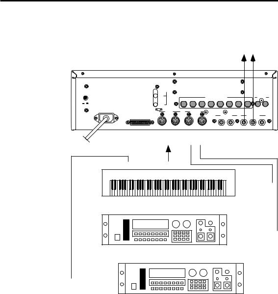
Hooking Up Your System
The following diagram shows how to hook up the MPC2000 to a MIDI keyboard and two sound modules.
MPC2000 |
TO AUDIO CONSOLE |
|
|
|
||||
|
|
|
|
|
|
|
|
|
SMPTE |
|
|
|
|
|
|
|
|
POWER |
|
|
|
|
|
|
|
|
IN |
|
|
ASSIGNABLE MIX OUT |
|
|
DIGITAL |
||
|
|
|
|
8 |
||||
|
1 |
2 3 |
4 |
5 |
6 7 |
IN |
OUT |
|
ON OFF |
|
|
|
|
|
|
|
|
OUT |
|
|
|
|
|
|
|
|
MIDI IN |
|
MIDI OUT |
|
|
|
|
|
|
1 |
2 |
A |
B |
RECORD IN |
STEREO OUT |
|||
SCSI |
|
|
|
LEFT |
RIGHT |
LEFT |
RIGHT |
PHONES |
MIDI IN MIDI OUT
TO 1—2 A---B
POWER
MIDI THRU MIDI OUT
MIDI IN
MULTI TIMBRAL MIDI KEYBOARD
MIDI IN
MULTI TIMBRAL MIDI SOUND MODULE
 MIDI IN
MULTI TIMBRAL MIDI SOUND MODULE
If you only want to use the MPC2000 as a drum machine for now, donÕt connect the MIDI keyboard, the sound modules, or make any MIDI connections. If you choose to connect an external MIDI device, connect the MIDI Output of the MIDI keyboard to MIDI Input of the MPC2000, and the MIDI Input of the MIDI sound source to MIDI Output of the MPC2000. MIDI Output provides an A or B Output. Normally use Output A when there is only one sound source. If you want to use a sound source from the connected MIDI keyboard, connect the MIDI keyboard MIDI Input to the MPC2000 MIDI Output. (In this case, it is necessary to turn the Soft thru function on the MPC2000 off. For details, refer to ÒSetting the TrackÕs MIDI ChannelÓ on page 49.) To connect multiple sound sources, use the MIDI THRU jacks of the MIDI device. Connect the MIDI Output of the MPC2000 to the MIDI Input of the first MIDI sound source. Connect the MIDI THRU of the first MIDI sound source to the second MIDI sound source, and so on. MIDI can handle up to 16 data channels, the MPC2000 has MIDI Output A and B each with 16 channels enabling you to handle 32 channels of data.
Page 12
Chapter 2: The Basics
The Terms Used in MPC2000
Here are some definitions of terms used in the MPC2000 that you should know:
Sequence
A sequence is the most basic unit in creating data on the MPC2000. The performance data from a MIDI keyboard or pad is recorded on each track within a sequence. Each sequence has 64 tracks, each to which performance data can be recorded. It is possible to create up to 99 sequences.
Sequence
Track01 Piano
Track02 Bass
Track03 Organ
Track64 (Unused)
There are two main ways to create music data on the MPC2000. One way is to create a long sequence as a whole piece, the other way is to create short sequences for each part of the piece and play them sequentially using the Song feature. Therefore, a sequence can be a long piece of more than 100 bars, a two-bar drum loop, etc.
One sequence as a whole piece.
SONG
Sequence
A multiple sequence piece (setting short sequences with the Song function).
SONG
Song
Seq |
|
Seq |
|
Seq |
|
Seq |
|
Seq |
|
Seq |
|
|
|
|
|
|
|
|
|
|
|
Track
There are 64 tracks in a sequence to which individual performances can be recorded. For example, track 1 could be the piano, track 2 could be the bass, and track 3 the organ. Normally, each track is recorded one at a time. It is also possible to record a new track while playing the recorded tracks. Each track can be turn on or off individually. It is possible to record different piano solos to track 1 and track 2 and compare the combination with the other tracks. It is possible to selected either a Drum track or MIDI track. It is possible to play the internal sampler from a drum pad and record it to the Drum track. If you are recording a piano or bass line from an external MIDI keyboard, set the track to MIDI.
Page 13

Chapter 2: The Basics
Song
This function sequentially plays the data of a sequence. You can set the order or number of times to play the sequence. This is used to play multiple pieces consecutively, or to complete a song by arranging the sequence data for each part. In the MPC2000 there are 20 songs, each having up to 250 steps. A sequence is assigned to each step to create a song. In doing so, it is also possible to set each step to repeat a number of times.
|
|
Song |
|
|
|
|
|
|
|
||
|
|
Step |
Seq |
Repeats |
|
|
1 |
|
1 |
2 |
|
|
2 |
|
10 |
1 |
|
|
3 |
|
1 |
2 |
|
|
4 |
|
23 |
3 |
|
|
250 |
|
|
|
|
|
|
|
|
|
|
Sound
Each individually sampled recording in the MPC2000 is called a sound. A sound can be recorded on the SMPLE page or loaded from a floppy disk. The start of end of a sound can be changed or the looping of a sound can be set on the TRIM page. The sound is assigned to a note number and it is possible to set the envelope, filter, or pitch. Assign a note number to each pad to play the sound from the MPC2000 pad.
Drum Pads
Sounds are played by assigning them to a drum pad. It is possible to assign up to 64 sounds by combining the pads with the pad bank keys(16 pads x 4 pad banks). To play a sound from a pad, assign a sound to a note number then assign the note number to a pad. Details are described in the ÒCreating and Editing ProgramsÓ chapter. By playing a pad, it is also possible to send the MIDI note of the note number assigned to that pad from the MIDI output.
Note Number
This refers to the position (note) of the MIDI note event on the keyboard. For example, the note number for Middle C on the piano is 60. The lowest key on the piano is A-1 which is note number 21. On a MIDI track, the MIDI keyboard performance data is recorded as a note number. On a Drum track, the note number is used to play back the sound in the internal sample. If you play the pads and record to a drum track, the note numbers assigned to the pad will be recorded on the track. When you play back this track, the sound assigned to the note number is played back.
Page 14
Chapter 2: The Basics
Program
A program is a collection of sounds assigned to 64 note numbers. It is possible to set the envelope or filter on each note number individually. It is possible to create 24 programs on the MPC2000.
The sound is played back by a pad or MIDI note only when it is assigned to a note number in a program. By assigning a note number to a pad, the sound assigned to that note number can be played from a pad. When a sequence is played back, the sound is played with the note data recorded on the track. (When the snare drum is assigned to note number 50, the snare drum is reproduced with the timing recorded on the note.)
You can instantly switch the program by selecting it in PROGRAM mode. It is also possible to use the MIDI program change feature to switch the program.
Page 15
Chapter 2: The Basics
Operating the Front Panel and Screen
Before you can use the MPC2000, you must learn how to use the cursor keys, data fields, numeric key pad, and the Function keys.
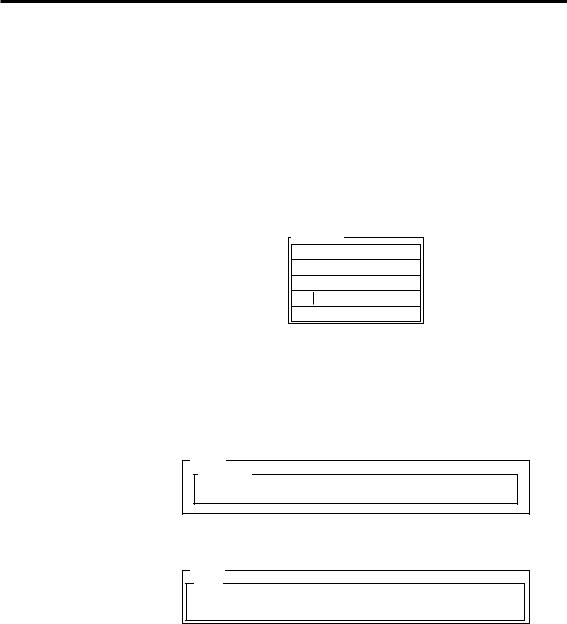
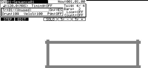
Insert the system disk and turn the power on. After about half a minute, the LCD screen will display the following text:
It is the main operating state of the MPC2000 and most playing and recording of sequences is done when this screen is in view. It will be discussed further in the chapter entitled ÒRecording Sequences.Ó If at any time while operating the MPC2000 you are confused and want to return to this screen, press the MAIN SCREEN key.
The Cursor, Cursor Keys, Data Fields
Make sure that the Main screen is showing. If not, press MAIN
SCREEN.
Notice that a part of the screen is displayed with black and white reversed. This is called the cursor. It is possible to move the cursor around the screen using the four gray direction keys located in the Cursor section of the panel. These four keys are referred to as the CURSOR LEFT, CURSOR RIGHT, CURSOR UP and CURSOR DOWN keys. Try moving the cursor around the LCD, then move it to the upper left corner.
Notice that the cursor does not move from letter to letter, but landing only in certain locations, usually to the right of a colon (:). These areas are called data fields and each one controls a specific parameter. For example, the upper left-most data field is called Sq (Sequence), an abbreviation for sequence. To the right of this field is another field containing the name for the selected sequence.
The Numeric Keypad and DATA Wheel
Make sure that the Main screen is displayed. If not, press the MAIN
SCREEN key.
To change the data in a data field, move the cursor to the field and use the DATA wheel. By rotating the DATA wheel one click to the right when the cursor is in the data field, the number on the screen will increase. By rotating the DATA wheel one click to the left, the number on the screen will decrease. If you continuously rotate the DATA wheel, the numbers will continuously increase or decrease.
Page 16

Chapter 2: The Basics
There are fields in the data field where you can enter the numbers directly from a numeric keypad. Move the cursor to the field, enter a new number from the numeric keypad, and press the ENTER key. For example, to change the tempo to 100.0, follow the steps below:
1.Move the cursor to the :  :(Tempo) field.
2.Enter 1000 (ignoring the decimal point) from the numeric keypad and press the ENTER key.
There are fields to select functions instead of entering numbers. Rotate the DATA wheel to select these functions. For example, move the cursor to the Timing field . Rotate the DATA wheel one click at a time and check the display change in the field. After you have finished, turn the field Ò OFFÓ.
The Function Keys
Make sure that the Main screen is showing. If not, press the MAIN SCREEN key.
Immediately below the LCD screen are six keys labeled F1, F2, F3, F4, F5 and F6. The functions of these keys change from one screen to another; these functions are always displayed on the lowest line of the screen. For example, while the Main screen is showing, the lowest line appears as:
When a function has a frame such as  , the function will be implemented. When the function is reversed such as
  , you can move to the page by pressing the corresponding function key. Press
  [F2]. If only characters are displayed as in the case of
  in [F1], the display will show that the page is currently selected. Most of the screen displays in the MPC2000 have function key functions, and the lowest line of each of these screens indicates the function of the six function keys while that screen is showing. Some screens have fewer than six active function keys and some have none.
Page 17
Chapter 2: The Basics
Basic Functions
Loading the Operating System
To operate the MPC2000, it is necessary to load the operating system from the system disk. To load the operating system, insert the enclosed operation disk into the disk drive of the MPC2000 and turn the power on. When the power is turned on, the version number of the operating system will be displayed for several seconds and the main screen will appear.
Note: The MPC2000 requires operating system software to turn the power on in the same way as personal computers. Personal computers have operating systems on the hard disk which is automatically loaded when the power is turned on. In the case of MPC2000, the operating system software is stored on the system disk and it is always necessary to use the system disk when you are turning the power on. The system disk is essential in operating the MPC2000 and it is therefore recommended to have several copies of the operating system. The way to copy a system disk is described in the ÒDisk OperationÓ chapter of this manual.
Loading and Playing Programs
All sounds and programs are stored on the memory held in RAM and the data is therefore lost whenever the power is turned off. In order to play any sounds after turning the power on, you must load them in from the disk. The procedure for loading files from a disk is described in the ÒDisk OperationÓ chapter of this manual, but to get you started quickly, the following steps enable you to load a disk from the enclosed disk and play the sounds from drum pads:
1.Insert ÒDisk#1 STANDARD SETÓ enclosed into the MPC2000. If the system disk is left in the disk drive, press the eject button to remove the system disk and insert ÒDisk#1.Ó
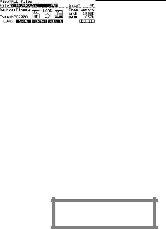
2.Press the DISK key (3 on the numeric keypad) while holding down the SHIFT key.
3. Select Ò STANDARD_SET .PGMÓ with the DATA wheel and press DO IT[F6].
Page 18
 Loading...