


Music production Center
SERVICE MANUAL
1
SAFETY INSTRUCTIONS |
INFORMATIONS |
|
|
1.Parts identified by the symbol are critical for safety. Replace them only with the parts number specified.
2.In addition to safety, other parts and assemblies are specified for conformance with such regulations as those applying to spurious radiation.
These must also be replaced only with the specified replacements.
Examples : Noise blocking capacitors, noise blocking filters, etc.
3.Use specified internal wiring. Note especially :
1)Wires covered with PVC tubing
2)Double insulated wires
3)High voltage leads
4.Use specified insulating materials for hazardous live parts. Note especially :
1)Insulation Tape
2)PVC tubing
3)Spacers (insulating barriers)
4)Insulation sheets for transistors
5)Plastic screws for fixing micro switches
5.When replacing AC primary side components (transformers, power cords, noise blocking capacitors, etc.), wrap the ends of the wires securely around the terminals before soldering.
6.Make sure that wires do not contact heat producing parts (heat sinks, oxide metal film resistors, fusible resistors, etc.).
7.Check that replaced wires do not contact sharp edged or pointed parts.
8.Also check areas surrounding repaired locations.
9.Make sure that foreign objects (screws, solder droplets, etc.) do not remain inside the set.
SAFETY CHECK AFTER SERVICING
After servicing, make measurements of leakage-current or resistance in order to determine that exposed parts are acceptably insulated from the supply circuit. The leakagecurrent measurement should be done between accessible metal parts (such as chassis, ground terminal, microphone jacks, signal input/output connectors, etc.) and the earth ground through a resistor of 1500 ohms paralleled with a 0.15 F capacitor, under the unit’s normal working conditions.
The leakage-current should be less than 0.5 mA rms AC. The resistance measurement should be done between accessible exposed metal parts and power cord plug prongs with the power switch (if included) “ON”. The resistance should be more than 2.2 M ohms.
SYMBOLS FOR PRIMARY DESTINATION
Unit destinations are indicated with letters as shown below.
Symbols |
Principal Destinations |
||
|
|
|
U.S.A |
|
A |
||
|
|
|
|
|
|
|
England |
|
B |
||
|
|
|
|
|
|
|
Europe |
|
E |
||
|
|
|
|
|
|
|
Japan |
|
J |
||
|
|
|
|
|
|
|
Germany |
|
V |
||
|
|
|
|
|
|
|
Japan |
|
X1 |
||
|
|
|
|
|
|
|
Universal Area |
|
X4 |
||
|
|
|
|
MAKE YOUR CONTRIBUTION TO PROTECT THE ENVIRONMENT
Used batteries with the ISO symbol for recycling as well as small accumulators (rechargeable batteries), mini-batteries (cells) and starter batteries should not be thrown into the garbage can.
Please leave them at an appropriate depot.
PRECAUTIONS FOR LITHIUM BATTERY
The lithium battery may explode when incorrectly replaced. [OBSERVE THE FOLLOEING WHEN REPLACING]
Replace with the same make and type or equivalent recom mended by manufacturer.
Place battery in correct polarity.
Do not short the terminals.
Do not charge battery.
Do not dispose of battery in fire.
SERVICE MANUAL
2

I. SPECIFICATIONS
|
General |
|
Display |
240 x 64 dot graphic LCD w/back light |
|
Memory card slot |
Compact Flash (The size of the compact flash card the MPC1000 can |
|
handle is from 32MB to 2GB) |
||
|
||
Dimentions (W x H x D) |
330 x 75.5 x 228.2(Max 234.6) |
|
Weight |
3.45kg |
|
Power reqirement |
19W |
|
|
Sound generator |
|
Sampling rate |
44.1kHz |
|
Memory capacity |
16MB standard (11.5MB for sound memory), expandable to 128MB |
|
Recording time |
136sec. (16MB, MONO), 24m28sec. (128MB, MONO) |
|
Memory expansion slot |
1 x for optional EXM128 |
|
Data format |
16-bit linear |
|
Polyphony |
32 |
|
Dynamic filtering |
2 x 2-pole filter per voice |
|
Filter type |
Low pass, Band pass, High pass |
|
Preset sound memory |
5MB |
|
Number of programs |
24 |
|
|
Effects |
|
Effects |
2 stereo effects and Master effect |
|
|
Chorus, Flanger, Bit grunger, 4 band EQ, Compressor, Phase shifter, |
|
Effect type |
Tremolo, Flying pan, Reverb |
|
|
Master effect: 4 band EQ, Compressor |
|
|
Sequencer |
|
Maximum events |
100,000 notes |
|
Resolution |
96 parts per 1/4-note |
|
Sequences |
99 |
|
Tracks per sequence |
64 |
|
MIDI output channels |
32 (16 channels x 2 outputs) |
|
Song mode |
20 songs, 250 steps per song |
|
Drum pad |
16 (velocity and pressure sensitive) |
|
Drum pad banks |
4 |
|
Sync mode |
MIDI clock |
* The specifications are subject to change without the prior notice.
SERVICE MANUAL
3

|
Inputs / Outputs |
|
Record input (L and R) |
1/4-inch stereo phone x 2, balanced -40dBu, input impedance 11k ohms; |
|
Max. Input level +10dBu |
||
|
||
Digital input |
RCA-pin x 1 S/PDIF |
|
Stereo output (L and R) |
1/4-inch phone x 2 unbalanced +11dBu, output impedance 1k Ohms, Max. |
|
output level +17dBu |
||
|
||
4 individual outputs |
1/4-inch phone x 4 unbalanced +11dBu, output impedance 1k Ohms, Max. |
|
output level +17dBu |
||
|
||
Phones output |
1/4-inch stereo phone x 1, 200mW / 100 ohms |
|
Digital output |
RCA-pin x 1 S/PDIF |
|
MIDI inputs |
5-pin DIN x 2 |
|
MIDI outputs |
5-pin DIN x 2 |
|
|
Slave connector x 1, USB MASS STORAGE CLASS support. |
|
USB |
(You need Windows 2000/Me/XP or later version, or MacOS 9.x/10.x or later |
|
|
version. ) |
|
Footswitches |
1/4-inch phone x 2 |
|
|
Standard accessories |
|
Standard accessories |
32MB Compact Flash card, Power cable, Operator's manual |
|
|
Options |
|
EXM128 |
128MB expansion memory card |
|
|
Data Compatibility (THRU Computer) |
|
MPC2000XL |
SEQ, WAV, PGM (Most parameters of PGM file can be loaded.) |
|
MPC4000 |
SEQ, WAV , PGM (DRUM program only. Only note assign and tune are |
|
loaded.) |
||
|
||
MPC3000 |
No compatibility |
|
Z4/Z8 |
WAV only |
|
S5000/6000 |
WAV only |
|
S1000/3000 |
No compatibility |
* The specifications are subject to change without the prior notice.
SERVICE MANUAL
4
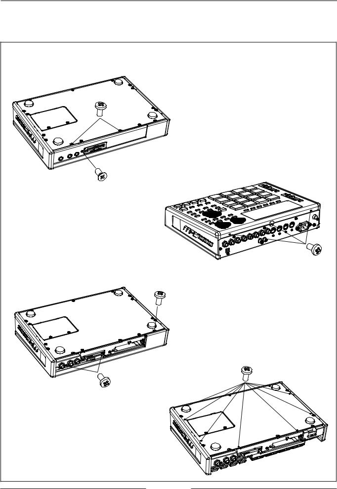
II. DISASSEMBLY
In case of trouble, etc., necessitating dismantling, please dismantle in the order shown in the illustrations. Reassemble in the reverse order.
ZS-820454X |
ZS-820455X |
ZS-820454X |
ZS-820454X |
ZS-820454X |
ZS-820454X |
SERVICE MANUAL
5

III. PRINCIPAL PARTS LOCATION
EM - 821776X |
BA - L4033A502A |
IND LCD PS24064LRU - ETA - H03 |
PC OPERATION - R BLK |
BA - L4033A502D |
|
PC OPERATION - F BLK |
|
BA - L4033A502C |
BA - L4033A502B |
|
|
|
|
|
|
|
|
|
|
|
|
|
|
|
|
|
|
|
|
|
|
|
|
|
|
|
|
|
|
||||||||||||||||||||||||||||||||||||||||||||||||||
PC OPERATION - L BLK |
PC PAD BLK |
|
|
|
|
|
|
|
|
|
|
|
|
|
|
|
|
|
|
|
|
|
|
|
|
|
|
|
|
|
|
||||||||||||||||||||||||||||||||||||||||||||||||||
|
|
|
|
|
|
|
|
|
|
|
|
|
|
|
|
|
|
BA - L4033A501A |
|
|
BA - L4033A502E |
|
|
|
|
|
BA - L4033A501E |
||||||||||||||||||||||||||||||||||||||||||||||||||||||
|
|
|
|
|
|
|
|
|
|
|
|
|
|
|
|
|
|
PC CPU BLK |
|
|
PC MIDI BLK |
|
|
|
|
|
PC FILTER BLK |
||||||||||||||||||||||||||||||||||||||||||||||||||||||
|
|
|
|
|
|
|
|
|
|
|
|
|
|
|
|
|
|
|
|
|
|
|
|
|
|
|
|
|
|
|
|
|
|
|
|
|
|
|
|
|
|
|
|
|
|
|
|
|
|
|
|
|
|
|
|
|
|
|
|
|
|
|
|
|
|
|
|
|
|
|
|
|
|
|
|
|
|
|
|
|
|
|
|
|
|
|
|
|
|
|
|
|
|
|
|
|
|
|
|
|
|
|
|
|
|
|
|
|
|
|
|
|
|
|
|
|
|
|
|
|
|
|
|
|
|
|
|
|
|
|
|
|
|
|
|
|
|
|
|
|
|
|
|
|
|
|
|
|
|
|
|
|
|
|
|
|
|
|
|
|
|
|
|
|
|
|
|
|
|
|
|
|
|
|
|
|
|
|
|
|
|
|
|
|
|
|
|
|
|
|
|
|
|
|
|
|
|
|
|
|
|
|
|
|
|
|
|
|
|
|
|
|
|
|
|
|
|
|
|
|
|
|
|
|
|
|
|
|
|
|
|
|
|
|
|
|
|
|
|
|
|
|
|
|
|
|
|
|
|
|
|
|
|
|
|
|
|
|
|
|
|
|
|
|
|
|
|
|
|
|
|
|
|
|
|
|
|
|
|
|
|
|
|
|
|
|
|
|
|
|
|
|
|
|
|
|
|
|
|
|
|
|
|
|
|
|
|
|
|
|
|
|
|
|
|
|
|
|
|
|
|
|
|
|
|
|
|
|
|
|
|
|
|
|
|
|
|
|
|
|
|
|
|
|
|
|
|
|
|
|
|
|
|
|
|
|
|
|
|
|
|
|
|
|
|
|
|
|
|
|
|
|
|
|
|
|
|
|
|
|
|
|
|
|
|
|
|
|
|
|
|
|
|
|
|
|
|
|
|
|
|
|
|
|
|
|
|
|
|
|
|
|
|
|
|
|
|
|
|
|
|
|
|
|
|
|
|
|
|
|
|
|
|
|
|
|
|
|
|
|
|
|
|
|
|
|
|
|
|
|
|
|
|
|
|
|
|
|
|
|
|
|
|
|
|
|
|
|
|
|
|
|
|
|
|
|
|
|
|
|
|
|
|
|
|
|
|
|
|
|
|
|
|
|
|
|
|
|
|
|
|
|
|
|
|
|
|
|
|
|
|
|
|
|
|
|
|
|
|
|
|
|
|
|
|
|
|
|
|
|
|
|
|
|
|
|
|
|
|
|
|
|
|
|
|
|
|
|
|
|
|
|
|
|
|
|
|
|
|
|
|
|
|
|
|
|
|
|
|
|
|
|
|
|
|
|
|
|
|
|
|
|
|
|
|
|
|
|
|
|
|
|
|
|
|
|
|
|
|
|
|
|
|
|
|
|
|
|
|
|
|
|
|
|
|
|
|
|
|
|
|
|
|
|
|
|
|
|
|
|
|
|
|
|
|
|
|
|
|
|
|
|
|
|
|
|
|
|
|
|
|
|
|
|
|
BA - L4033A501B
PC AD/DA BLK
BA - L4033A501C |
BA - L4033A501D |
BP - 821839X |
PC FRONT BLK |
PC HD CONNECT BLK |
SW POW SNP - 9031 |
SERVICE MANUAL
6

IV. SUPPLEMENTARY INFORMATION
[Update procedure]
===How to copy the OS binary file to a CF card using a MPC1000 and a computer==== Below procedure will utilize the MPC1000 as a Compact flash writer.
Required Equipment :
Compact Flash (CF), Computer with USB mass storage class support (Windows XP/ME/2000 or Mac OSX, OS9.x)
1. Copy/Download the OS data to a computer ’s hard disc drive and extract it ’s data.
2.Insert a Compact Flash card into the MPC1000.
3.Turn on the power of the MPC1000.
4.Go to Load mode, then press USB (F4).
5.Connect a USB cable between the computer and the MPC1000. (Display will change from “Status=Not Connected ” to “Status=Connected ”)
6.The CF in the MPC1000 will be mounted as a drive on the computer.
7.Copy the OS binary file to the CF in the MPC1000.
8. Disconnect the USB cable. (MPC1000 will not accept any user in put while a USB cable is connected)
Note: The OS data can also be copied to a Compact Flash card using any other Compact
Flash card reader/writer. In this case it is not necessary to connect the MPC1000 to a computer.
====How to update the MPC1000====
MPC1000 is updated using a Compact Flash card containing OS data. 1. Insert a CF containing OS data into the MPC1000.
2. Turn on the power of the MPC1000 while pressing down the “Window ” button.
3. To start the update process, p ress the “REC” button. After the update process is finished the MPC1000 will re - boot automatically. Note: The MPC1000 can not be updated from a computer via USB directly – updating is only possible using a CF card.
====Hidden model==== ( Note: V1.06 is not supported.)
The MPC1000 has the following hidden modes, which can be accessed by certain input sequences or holding down a key while powering on the unit. Currently these modes are not supported in OS Version 1.06.
1.[Owner Name]
Mode > Other > F3/FOOTSW > F6 > Enter owner name in the startup screen, “Owner Name” will be displayed.
2. [Initialize parameter]
Hold down the ERASE button while powering on the unit.
3. [Memory Check]
Hold down the PLAY button while powering on the unit.
4.[Demo mode ]
Hold down the Bank “D” button while powering on the unit.
In this mode “Internal memory” on the Save page can not be selected . In the startup screen “Demo” will be displayed instead of “MPC1000”. Once demo mode has been activated it will remain active even if power is turned off and on again. To turn off the Demo mode, hold down the Bank “D” button while powering on the unit.
SERVICE MANUAL
7
 Loading...