


 Loading...
®
ONline 17-Slot System
Concentrator Installation and
Operation Guide
Document Number 17-00417-3
Printed March 1995
Model Numbers: 5017C-LS 5017C
5017C with load sharing
3Com Corporation
118 Turnpike Road
Southborough, MA 01772-1886
U.S.A.
(508) 460-8900
FAX (508) 460-8950

Federal Communications Commission
Notice
This equipment has been tested and found to comply with the limits for a Class A digital device, pursuant to Part 15 of the FCC Rules. These limits are designed to provide reasonable protection against harmful interference when the equipment is operated in a commercial environment. This equipment generates, uses, and can radiate radio frequency energy and, if not installed and used in accordance with the instruction manual, may cause harmful interference to radio communications. Operation of this equipment in a residential area is likely to cause harmful interference, in which case you must correct the interference at your own expense.
Canadian Emissions Requirements
This Class A digital apparatus meets all requirements of the Canadian Interference-Causing Equipment Regulations.
Cet appareil numérique de la classe A respecte toutes les exigences du Règlement sur le matériel brouilleur du Canada.
VDE Class B Compliance
Hiermit wird bescheinigt, dass der 5017C und 5017C-LS in Üebereinstimmung mit den Bestimmungen der Vfg 243/1991 funkentstöert ist.
Der Deutschen Bundespost wurde das Inverkehrbringen dieses Geraetes angezeigt und die Berechtigung zur Üeberprüefung der Serie auf Einhaltung der Bestimmungen eingeräeumt.
Einhaltung mit betreffenden Bestimmugen kommt darauf an, dass geschirmte Ausfuehrungen gebraucht werden. Fuer die Beschaffung richtiger Ausfuehrungen ist der Betreiber verantwortlich.
This is to certify that the 5017C and 5017C-LS are shielded against radio interference in accordance with the provisions of Vfg 243/1991.
The German Postal Services have been advised that this equipment is being placed on the market and that they have been given the right to inspect the series for compliance with regulations.
Compliance with applicable regulations depends on the use of shielded cables. The user is responsible for procuring the appropriate cables.
EN55022/CISPR22 Compliance
This equipment conforms to the Class A emissions limits for a digital device as defined by EN55022 (CISPR22).
VCCI Class 1 Compliance
This equipment is in the 1st Class category (information equipment to be used in commercial or industrial areas) and conforms to the standards set by the Voluntary Control Council for Interference by Information Technology Equipment aimed at preventing radio interference in commercial or industrial areas.
Consequently, when the equipment is used in a residential area or in an adjacent area, radio interference may be caused to radio and TV receivers, and so on.
Read the instructions for correct handling.
UK General Approval Statement
The ONcore Switching Hub, ONline System Concentrator, and ONsemble StackSystem Hub are manufactured to the International Safety Standard EN 60950 and are approved in the UK under the General Approval Number NS/G/12345/J/100003 for indirect connection to the public telecommunication network.
Disclaimer
The information in this document is subject to change without notice and should not be construed as a commitment by 3Com Corporation. 3Com Corporation assumes no responsibility for any errors that may appear in this document.
Copyright Statement
© 1995 by Chipcom Corporation, a subsidiary of 3Com Corporation. Printed in U.S.A. All rights reserved. The information contained herein is the exclusive and confidential property of 3Com Corporation. No part of this manual may be disclosed or reproduced in whole or in part without permission from 3Com Corporation.
Trademarks
Because of the nature of this material, numerous hardware and software products are mentioned by name. In most, if not all cases, these product names are claimed as trademarks by the companies that manufacture the products. It is not our intent to claim these names or trademarks as our own.
Artel, Chipcom, Ethermodem, Galactica, ONcore, ORnet, StarBridge, and TriChannel are registered trademarks of Chipcom Corporation, a subsidiary of 3Com Corporation.
Chipcom OpenHub, G-Man, LANsentry, MultiProbe, ONdemand, ONline, ONsemble, PowerRing, SL2000, SL3000, SL4000, StackJack, StackSystem, and SwitchCentral are trademarks of Chipcom Corporation, a subsidiary of 3Com Corporation.
ii ONline 17-Slot System Concentrator Installation and Operation Guide
The Chipcom Multichannel Architecture Communications System is registered under U.S. Patent Number 5,301,303.
UNIX is a registered trademark in the U.S.A. and other countries licensed exclusively through X/Open Company, Ltd.
XNS is a trademark of Xerox Corporation.
DEC, DECnet, the Digital logo, DELNI, POLYCENTER, VAX, VT100, and VT220 are trademarks of Digital Equipment Corporation.
3ComFacts, Ask 3Com, CardFacts, NetFacts, and CardBoard are service marks of 3Com Corporation.
3Com, LANplex, BoundaryRouting, LanScanner, LinkBuilder, NETBuilder, NETBuilderII, ParallelTasking, ViewBuilder, EtherDisk, Etherl\Link, EtherLink Plus, EtherLink II, TokenLink, TokenLink Plus, and TokenDisk are registered trademarks of 3Com Corporation.
3ComLaser Library, 3TECH, CacheCard, FDDILink, FMS, NetProbe, SmartAgent, Star-Tek, and Transcend are trademarks of 3Com Corporation.
CompuServe is a registered trademark of CompuServe, Inc.
3Com registered trademarks are registered in the United States, and may or may not be registered in other countries. Other brand and product names may be registered trademarks or trademarks of their respective holders.
Restricted Rights
Use, duplication, or disclosure by the Government is subject to restrictions as set forth in subparagraph (c)(1) (ii) of the Rights in Technical Data and Computer Software clause at
DFARS 252.227-7013.
Printed on recycled paper.
ONline 17-Slot System Concentrator Installation and Operation Guide iii
iv ONline 17-Slot System Concentrator Installation and Operation Guide
Contents
How to Use This Guide
Audience . . . . . . . . . . . . . . . . . . . . . . . . . . . . . . . . . . . . . . . . . . . . . . . . . . xiii Structure of This Guide . . . . . . . . . . . . . . . . . . . . . . . . . . . . . . . . . . . . . . . . xiv Document Conventions . . . . . . . . . . . . . . . . . . . . . . . . . . . . . . . . . . . . . . . xv Related Documents . . . . . . . . . . . . . . . . . . . . . . . . . . . . . . . . . . . . . . . . . . xvi 3Com Documents . . . . . . . . . . . . . . . . . . . . . . . . . . . . . . . . . . . . . . . .xvii Reference Documents . . . . . . . . . . . . . . . . . . . . . . . . . . . . . . . . . . . . .xvii
Chapter 1 — Introduction
Introducing the ONline System Concentrator . . . . . . . . . . . . . . . . . . . . . . .1-1
Back Panel . . . . . . . . . . . . . . . . . . . . . . . . . . . . . . . . . . . . . . . . . . . . . .1-3
Front Panel . . . . . . . . . . . . . . . . . . . . . . . . . . . . . . . . . . . . . . . . . . . . .1-3
ONline System Concentrator Features . . . . . . . . . . . . . . . . . . . . . . . . . . . . .1-4
Modular Design . . . . . . . . . . . . . . . . . . . . . . . . . . . . . . . . . . . . . . . . . .1-5
TriChannel Architecture . . . . . . . . . . . . . . . . . . . . . . . . . . . . . . . . . . . .1-6
Port-Switching Technology . . . . . . . . . . . . . . . . . . . . . . . . . . . . . . . . . .1-6
Fault-Tolerance Capabilities . . . . . . . . . . . . . . . . . . . . . . . . . . . . . . . . . .1-8
Backup Power Supply . . . . . . . . . . . . . . . . . . . . . . . . . . . . . . . . . . .1-8
Load Sharing . . . . . . . . . . . . . . . . . . . . . . . . . . . . . . . . . . . . . . . . .1-8
Backup Controller Module . . . . . . . . . . . . . . . . . . . . . . . . . . . . . . .1-9
Redundant Cable Links . . . . . . . . . . . . . . . . . . . . . . . . . . . . . . . . . .1-9
Backup Concentrator . . . . . . . . . . . . . . . . . . . . . . . . . . . . . . . . . .1-10
Hot Swapping of Media Modules . . . . . . . . . . . . . . . . . . . . . . . . . . . .1-11
Synchronous Backplane . . . . . . . . . . . . . . . . . . . . . . . . . . . . . . . . . . .1-12
Chapter 2 — Installation and Troubleshooting
Contents of the Shipping Box . . . . . . . . . . . . . . . . . . . . . . . . . . . . . . . . . . .2-1
FCC Regulations . . . . . . . . . . . . . . . . . . . . . . . . . . . . . . . . . . . . . . .2-3
Site Selection Considerations . . . . . . . . . . . . . . . . . . . . . . . . . . . . . . . . . . .2-4
ONline 17-Slot System Concentrator Installation and Operation Guide v
Location Requirements . . . . . . . . . . . . . . . . . . . . . . . . . . . . . . . . . . . . |
.2-4 |
Ventilation . . . . . . . . . . . . . . . . . . . . . . . . . . . . . . . . . . . . . . . . . . . . . |
.2-4 |
Power Requirements . . . . . . . . . . . . . . . . . . . . . . . . . . . . . . . . . . . . . |
.2-5 |
Rack Mount Installation Requirements . . . . . . . . . . . . . . . . . . . . . . . . |
.2-5 |
Table Top Installation Requirements . . . . . . . . . . . . . . . . . . . . . . . . . . |
.2-6 |
Installation . . . . . . . . . . . . . . . . . . . . . . . . . . . . . . . . . . . . . . . . . . . . . . . . |
.2-6 |
Installing the Cable Tray . . . . . . . . . . . . . . . . . . . . . . . . . . . . . . . . . . . |
.2-7 |
Cable Tray Rack Mounting . . . . . . . . . . . . . . . . . . . . . . . . . . . . . . |
.2-8 |
Cable Tray Table Mounting . . . . . . . . . . . . . . . . . . . . . . . . . . . . . |
2-10 |
Installing the ONline System Concentrator . . . . . . . . . . . . . . . . . . . . . |
2-11 |
Rack Mounting the ONline System Concentrator . . . . . . . . . . . . . |
2-11 |
Table Top Mounting the ONline Concentrator . . . . . . . . . . . . . . . |
2-13 |
Installing the Backup Power Supply (Optional) . . . . . . . . . . . . . . . . . . |
2-14 |
Selecting the Power Supply Voltage . . . . . . . . . . . . . . . . . . . . . . . . . . |
2-17 |
Installing ONline Modules . . . . . . . . . . . . . . . . . . . . . . . . . . . . . . . . . . |
2-19 |
Connecting Network Cables . . . . . . . . . . . . . . . . . . . . . . . . . . . . . . . . |
2-19 |
Power Up and Verification . . . . . . . . . . . . . . . . . . . . . . . . . . . . . . . . . |
2-20 |
Fan Operation Verification . . . . . . . . . . . . . . . . . . . . . . . . . . . . . . |
2-21 |
Power Supply Operation Verification . . . . . . . . . . . . . . . . . . . . . . |
2-21 |
Technical Assistance . . . . . . . . . . . . . . . . . . . . . . . . . . . . . . . . . . . . . . . . . |
2-25 |
Where To Go From Here . . . . . . . . . . . . . . . . . . . . . . . . . . . . . . . . . . . . . |
2-26 |
Chapter 3 — Maintenance
Routine Maintenance . . . . . . . . . . . . . . . . . . . . . . . . . . . . . . . . . . . . . . . . .3-2
Replacing the Power Supply . . . . . . . . . . . . . . . . . . . . . . . . . . . . . . . . . . . .3-2
Replacing the Fan Unit . . . . . . . . . . . . . . . . . . . . . . . . . . . . . . . . . . . . . . . .3-7
ONline Module Maintenance . . . . . . . . . . . . . . . . . . . . . . . . . . . . . . . . . . .3-9
Other System Components . . . . . . . . . . . . . . . . . . . . . . . . . . . . . . . . . . . . .3-9
Appendix A — Specifications
General . . . . . . . . . . . . . . . . . . . . . . . . . . . . . . . . . . . . . . . . . . . . . . . . . . A-1
Environmental . . . . . . . . . . . . . . . . . . . . . . . . . . . . . . . . . . . . . . . . . . . . . A-1
Mechanical . . . . . . . . . . . . . . . . . . . . . . . . . . . . . . . . . . . . . . . . . . . . . . . A-2
Power Source . . . . . . . . . . . . . . . . . . . . . . . . . . . . . . . . . . . . . . . . . . . . . . A-2
Regulatory Compliance . . . . . . . . . . . . . . . . . . . . . . . . . . . . . . . . . . . . . . . A-2
Accessories . . . . . . . . . . . . . . . . . . . . . . . . . . . . . . . . . . . . . . . . . . . . . . . A-3
vi ONline 17-Slot System Concentrator Installation and Operation Guide
Appendix B — Slot Usage Chart
Appendix C — Technical Support
On-line Technical Support . . . . . . . . . . . . . . . . . . . . . . . . . . . . . . . . . . . . . .C-1 Email Technical Support . . . . . . . . . . . . . . . . . . . . . . . . . . . . . . . . . . . .C-2 World Wide Web Site . . . . . . . . . . . . . . . . . . . . . . . . . . . . . . . . . . . . . .C-2 Support from Your Network Supplier . . . . . . . . . . . . . . . . . . . . . . . . . . . . .C-2 Support from 3Com . . . . . . . . . . . . . . . . . . . . . . . . . . . . . . . . . . . . . . . . . .C-3 Returning Products for Repair . . . . . . . . . . . . . . . . . . . . . . . . . . . . . . . . . . .C-4 Accessing the 3Com MIB . . . . . . . . . . . . . . . . . . . . . . . . . . . . . . . . . . . . . .C-4 3Com Technical Publications . . . . . . . . . . . . . . . . . . . . . . . . . . . . . . . . .C-5
Index
ONline 17-Slot System Concentrator Installation and Operation Guide vii
viii ONline 17-Slot System Concentrator Installation and Operation Guide
Figures
Figure 1-1. |
Multiple 17-Slot Concentrator Environment . . . . . . . . |
. . . .1-2 |
Figure 1-2. |
ONline System Concentrator Rear View . . . . . . . . . . . |
. . . .1-3 |
Figure 1-3. |
ONline System Concentrator Front View . . . . . . . . . . . |
. . . .1-4 |
Figure 1-4. |
Modular ONline Configuration . . . . . . . . . . . . . . . . . . |
. . . .1-5 |
Figure 1-5. |
ONline System Concentrator Using Multiple Networks |
. . . .1-7 |
Figure 1-6. |
Redundant Cable Link Configuration . . . . . . . . . . . . . |
. . .1-10 |
Figure 1-7. |
Backup Concentrator Configuration . . . . . . . . . . . . . . |
. . .1-11 |
Figure 2-1. |
ONline System Concentrator Shipping Box Contents . . |
. . . .2-2 |
Figure 2-2. |
Rack Mount Positions . . . . . . . . . . . . . . . . . . . . . . . . . |
. . . .2-9 |
Figure 2-3. |
Cable Tray Installation in Rack . . . . . . . . . . . . . . . . . . |
. . .2-10 |
Figure 2-4. |
Attaching the Rack Mount Flanges . . . . . . . . . . . . . . . . |
. .2-12 |
Figure 2-5. |
Chassis Mounted in Rack . . . . . . . . . . . . . . . . . . . . . . . |
. .2-13 |
Figure 2-6. |
Removing Fan Unit . . . . . . . . . . . . . . . . . . . . . . . . . . . . |
. .2-14 |
Figure 2-7. |
Unplugging the Fan Unit . . . . . . . . . . . . . . . . . . . . . . . |
. .2-15 |
Figure 2-8. |
Power Supply Connectors . . . . . . . . . . . . . . . . . . . . . . . |
. .2-16 |
Figure 2-9. |
Installing the Backup Power Supply . . . . . . . . . . . . . . . |
. .2-16 |
Figure 2-10. |
Installed Backup Power Supply . . . . . . . . . . . . . . . . . . . |
. .2-17 |
Figure 2-11. |
Setting the Voltage Selector Switch . . . . . . . . . . . . . . . |
. .2-18 |
Figure 2-12. |
Network Cable Connections . . . . . . . . . . . . . . . . . . . . . |
. .2-20 |
Figure 3-1. |
Removing the Power Supply . . . . . . . . . . . . . . . . . . . . . |
. . .3-3 |
Figure 3-2. |
Unplugging the Power Supply . . . . . . . . . . . . . . . . . . . |
. . .3-4 |
Figure 3-3. |
Power Supply Plugs in ONline System Concentrator . . . |
. . .3-5 |
Figure 3-4. |
Backup Power Supply Installed . . . . . . . . . . . . . . . . . . . |
. . .3-6 |
Figure 3-5. |
Removing the Fan Unit . . . . . . . . . . . . . . . . . . . . . . . . . |
. . .3-7 |
Figure 3-6. |
Unplugging the Fan Unit . . . . . . . . . . . . . . . . . . . . . . . |
. . .3-8 |
Figure 3-7. |
Fan Unit Installed . . . . . . . . . . . . . . . . . . . . . . . . . . . . . |
. . .3-9 |
ONline Ethernet 10BASE-FL Module Installation and Operation Guide ix
x ONline Ethernet 10BASE-FL Module Installation and Operation Guide
Tables
Table 2-1. Steps for Installing the ONline System Concentrator . . . . . .2-6 Table 2-2. Rack Mount Settings . . . . . . . . . . . . . . . . . . . . . . . . . . . . . .2-8 Table 2-3. Controller Module LEDs After Proper Power-Up . . . . . . . . .2-21 Table 2-4. Troubleshooting with Controller Module LEDs . . . . . . . . . .2-22 Table B-1. Concentrator Slot Usage Chart . . . . . . . . . . . . . . . . . . . . . .B-1
ONline Ethernet 10BASE-FL Module Installation and Operation Guide xi

How to Use This Guide
This guide explains how to install, operate, and manage the following 3Com ONline™ 17-Slot System Concentrators.
5017C
5017C with load sharing
5017C-LS
Keep this guide near the ONline System Concentrator
Audience
This guide is intended for the following people at your site:
Network manager or administrator
Hardware installer
ONline 17-Slot System Concentrator Installation and Operation Guide xiii

Structure of This Guide
This guide contains the following chapters:
Chapter 1, Introduction – Introduces the principal features of the ONline System Concentrator and provides a front and rear view of the unit.
Chapter 2, Installation and Troubleshooting – Provides illustrated procedures for installing and verifying the operation of the 17-Slot ONline System Concentrator.
Chapter 3, Maintenance – Describes how to order and replace serviceable parts on the ONline System Concentrator. These parts include the power supply, backup power supply, and fan units.
Appendix A, Specifications – Provides product dimensions, power requirements, and other specifications for the unit.
Appendix B, Slot Usage Chart – Provides a chart to record information about which modules are installed in the 17 concentrator slots.
Appendix C - Technical Support – Lists the various methods for contacting the 3Com technical support organization and for accessing other product support services.
Index
ONline 17-Slot System Concentrator Installation and Operation Guide xiv

Document Conventions
The following document conventions are used in this manual:
Convention |
Indicates |
Example |
|
|
|
|
|
Courier text |
User input |
In the Agent Information Form, |
|
|
|
|
enter MIS in the New Contact |
|
|
|
field. |
|
|
|
|
|
|
System output |
After pressing the Apply |
|
|
|
button, the system displays |
|
|
|
the message |
|
|
|
Transmitting data. |
|
|
|
|
Bold command |
Path names |
Before you begin, read the |
|
string |
|
readme.txt file located in |
|
|
|
|
/usr/snm/agents. |
|
|
|
|
Italic text in braces |
User-substituted |
Use the following command to |
|
|
|
identifiers |
show port details: |
|
|
|
SHOW PORT {slot.all} VERBOSE |
|
|
|
|
Capitalized text in |
Keyboard entry |
Type your password and press |
|
plain brackets |
by the user |
[ENTER]. |
|
|
|
|
|
Italics |
Text emphasis, |
Ensure that you press the Apply |
|
|
|
document titles |
button after you add the new |
|
|
|
search parameters. |
|
|
|
|
ONline 17-Slot System Concentrator Installation and Operation Guide xv

Convention |
Indicates |
Example |
|
|
|
Note: |
A Note. The |
Note: Use STP lobe |
|
information is |
cables for your system. |
|
important |
|
|
|
|
Caution: |
A Caution. A |
Caution: Do not put |
|
condition may |
your installation |
|
damage |
diskettes on a |
|
software or |
magnetic surface. |
|
hardware |
This may damage the |
|
|
diskettes. |
|
|
|
Warning: |
A Warning. A |
Warning: Wear eye |
|
condition may |
protection when |
|
threaten |
performing these |
|
personal safety |
maintenance |
|
|
procedures. |
|
|
|
Related Documents
This section provides information on supporting documentation, including:
3Com Documents
Reference Documents
xvi ONline 17-Slot System Concentrator Installation and Operation Guide
3Com Documents
The following documents provide additional information on 3Com products:
17-Slot ONline System Concentrator Installation and Operation Guide – Explains how to install, operate, and manage the 3Com ONline 17-Slot System Concentrator (Models 5017C-LS and 5017C with load sharing).
6-Slot ONline System Concentrator Installation and Operation
Guide – Explains how to install, operate, and manage the 3Com ONline 6-Slot System Concentrator.
ONline Token Ring Management Module User’s Guide – Explains how to install, operate, and use the 3Com ONline Token Ring Management Module.
ONline Management Commands Guide – Provides an alphabetized reference resource describing all ONline management commands.
For a complete list of 3Com documents, contact your 3Com representative.
Reference Documents
The following documents supply related background information:
Case, J., Fedor, M., Scoffstall, M., and J. Davin, The Simple Network Management Protocol, RFC 1157, University of Tennessee at Knoxville, Performance Systems International and the MIT Laboratory for Computer Science, May 1990.
Rose, M., and K. McCloghrie, Structure and Identification of Management Information for TCP/IP-based Internets, RFC 1155, Performance Systems International and Hughes LAN Systems, May 1990.
ONline 17-Slot System Concentrator Installation and Operation Guide xvii

1Introduction
This chapter briefly describes the capabilities and operation of the 3Com ONline™ System Concentrator. Chapter 2 provides important information for installing modules and verifying their operation.
If you are uncertain about legal network configurations when using the ONline System Concentrator, refer to the appropriate ONline media module manual.
Introducing the ONline System Concentrator
The ONline System Concentrator is a modular, fault-tolerant platform for facility networks. The concentrator has a unique TriChannel® architecture that allows it to run three network protocols concurrently. It is capable of running Ethernet, Token Ring, and FDDI networks - all in the same concentrator.
Ethernet connectivity is available on a variety of major cable types including:
Fiber optic cable
Unshielded and Shielded twisted pair wire
Thin and Thick coaxial cable
Introduction 1 - 1
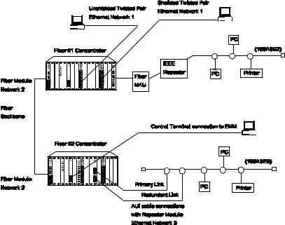
Figure 1-1 shows a model system that includes each of these cable types. In this diagram, an ONline Ethernet Repeater Module is connected to a 10BASE5 segment via an AUI cable and a transceiver. Also shown is the physical connection between an ONline Ethernet Fiber Module and a 10BASE2 segment, via a fiber cable, fiber media access unit, and IEEE repeater. Unshielded and shielded twisted pair connections to-the-desk are also included in this sample configuration.
Figure 1-1. Multiple 17-Slot Concentrator Environment
Network segments attach to the concentrator through media modules you install into the chassis. The ONline Controller Module, which provides re-timing and re-transmission of received signals, must be installed in one of the concentrator's seventeen slots. The remaining sixteen slots can be configured with any combination of media modules.
1 - 2 ONline 17-Slot System Concentrator Installation and Operation Guide
Back Panel
A power supply and DC fan unit are installed when you receive your concentrator. There is an On/Off switch on the power supply. The power supply should be powered down when you install or remove it. Note that there is no need to power down the concentrator for installation or removal of the media modules. Additionally, you can replace the fan unit with an optional backup power supply to provide power redundancy.
Figure 1-2. ONline System Concentrator Rear View
Front Panel
The concentrator is shipped with 15 blank faceplates and two empty slots. The two slots are left empty because you must install the ONline Controller Module and at least one media module for the concentrator to be functional. As you add media modules to your unit, remove blank faceplates to provide additional slots for the new modules.
Introduction 1 - 3
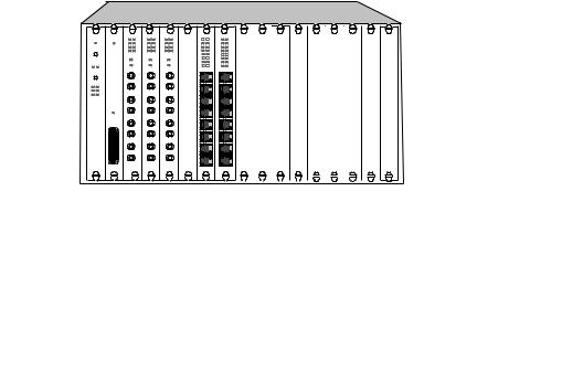
Figure 1-3. ONline System Concentrator Front View
A cable tray is provided with the concentrator so that cables you attach to the media modules can be run under the unit and out the back − where they will not be in the way. A rack mount kit is also provided for the concentrator and for the cable tray so you can rack mount the entire unit.
ONline System Concentrator Features
This section describes the major features of the ONline System
Concentrator. The features include:
Modular Design
TriChannel® Architecture
Port-Switching Technology
Fault-Tolerance Capabilities
Hot Swapping of Media Modules
Synchronous Backplane
1 - 4 ONline 17-Slot System Concentrator Installation and Operation Guide
Modular Design
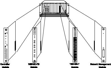
The ONline Concentrator's modular design lets you add different media modules (such as fiber, twisted pair, and coaxial) in any combination to connect different types of media segments. A possible configuration is shown in Figure 1-4. You can link segments of different protocols using Token Ring, FDDI, bridging and routing modules.
Every concentrator requires one Controller Module that controls communications between all modules. In addition, a Network Management Module provides sophisticated monitoring and control of the modules in the concentrator. As a rack-mounted unit, the ONline Concentrator can be connected to patch panels to simplify and manage your network cables.
Figure 1-4. Modular ONline Configuration
Introduction 1 - 5
TriChannel Architecture
The ONline System Concentrator's TriChannel architecture lets you run Ethernet, Token Ring, and FDDI networks, all in the same concentrator. This allows a single ONline unit to do the work of three conventional hubs. You can also run multiple Ethernet networks or mixture of Ethernet, Token Ring, and FDDI networks in any combination you want. This architecture is shown in Figure 1-5.
Any module you add to the concentrator can be assigned to any of three networks on its backplane and can be easily moved to another backplane network using either an on-board dip switch or remote network management.
Additionally, any module can be set to “isolated” mode whereby it acts as an isolated network - not connected to the concentrator backplane. This mode lets you isolate users from the main network. This can be useful for security or as a temporary situation to prevent traffic from contaminating the network (for example, if some users are conducting network tests or running at very high loads.)
Port-Switching Technology
Available port-switching modules allow you to assign any port to any backplane network using a network management command. This allows you to perform moves, adds, and changes at the network console, saving costly and time-consuming trips to the wiring closet. It also allows you to get additional bandwidth on demand by switching users to lower volume networks during peak traffic periods.
1 - 6 ONline 17-Slot System Concentrator Installation and Operation Guide

Figure 1-5. ONline System Concentrator Using Multiple Networks
Introduction 1 - 7
Loading...