


 Loading...
®
10BASE-FB Transceiver Installation Guide
Document Number 17-00325-3
Model Numbers: 5101T-FB-SMA 5101T-FB-ST 5101T-FB-FC
3Com Corporation
118 Turnpike Road
Southborough, MA 01772-1886
U.S.A.

Federal Communications
Commission Notice
This equipment has been tested and found to comply with the limits for a Class A digital device, pursuant to Part 15 of the FCC Rules. These limits are designed to provide reasonable protection against harmful interference when the equipment is operated in a commercial environment. This equipment generates, uses, and can radiate radio frequency energy and, if not installed and used in accordance with the instruction manual, may cause harmful interference to radio communications. Operation of this equipment in a residential area is likely to cause harmful interference in which case the user will be required to correct the interference at his own expense.
Canadian Emissions Requirements
Cet appareil numérique respecte les limites de bruits radioélectriques applicables aux appareils numériques de Class A prescrites dans le norme sur le materièl brouilleur : “Appareils Numériques”, NMB-003 édictée par le ministrè des Communications.
This digital apparatus does not exceed the Class A limits for radio noise emissions from digital apparatus as set out in the interfer- ence-causing equipment standard entitled “Digital Apparatus”, ICES-003 of the Department of Communications.
Page ii

VDE CLASS B COMPLIANCE
Hiermit wird bescheinigt, dass der (5101T-FB) in Uebereinstimmung mit den Bestimmungen der Vfg 243/1991 funk-entstort ist. Der Deutschen Bundespost wurde das Inverkehrbringen dieses Gerates engezeigt und die Berechtigung zur Ueberprufung der Serie auf Einhaltung der Bestimmungen eingeraumt.
This is to certify that the (5101T-FB) is shielded against radio interference in accordance with the provisions of Vfg 243/1991.
The German Postal Services have been advised that this device is being put on the market and that they have been given the right to inspect the series for compliance with the regulations.
CAUTION
Do not install in air ducts or plenums. For installation in other environmental air handling spaces, use only with cable classified by Underwriters Laboratories as to fire and smoke characteristics in accordance with Section 770-2(b) and Section 725- 2(b) of the National Electrical Code.
DISCLAIMER
The information in this document is subject to change without notice and should not be construed as a commitment by 3Com Corporation. 3Com Corporation assumes no responsibility for any errors that may appear in this document.
Page iii
COPYRIGHT STATEMENT
ø1996 by 3Com Corporation. All rights reserved. The information contained herein is the exclusive and confidential property of 3Com Corporation. No part of this manual may be disclosed or reproduced in whole or in part without permission from 3Com Corporation.
Printed in the U.S.A.
TRADEMARKS
Because of the nature of this material, numerous hardware and software products are mentioned by name. In most, if not all cases, these product names are claimed as trademarks by the companies that manufacture the products. It is not our intent to claim these names or trademarks as our own.
The ONline logo, TriChannel, and Midnight are trademarks, and Ethermodem, ORnet, ONcore, and Chipcom are registered trademarks of 3Com Corporation.
Ethernet is a registered trademark of Xerox Corporation.
DEC, the digital logo, DELNI, DECnet, and VAX are trademarks of Digital Equipment Corporation.
IBM is a registered trademark of International Business Machines.
Page iv

Table of Contents |
|
Table of Contents ................................................. |
v |
Preface .................................................................. |
1 |
Intended Audience ....................................... |
1 |
Transceiver Overview .......................................... |
3 |
Transceiver Top Panel.................................. |
3 |
Transceiver Front Panel........................................ |
6 |
Transceiver Rear Panel......................................... |
7 |
Alternate Collision Mode ............................. |
9 |
SQE Test .................................................... |
10 |
High Power (PWR) .................................... |
10 |
Half Step Mode .......................................... |
11 |
Installation .......................................................... |
11 |
Site Preparation and Placement.................. |
12 |
Unpacking Procedures........................................ |
13 |
Verifying Transceiver Switch Settings............... |
14 |
Connecting to Ethernet V2.0 and IEEE 802.3 |
|
Controllers .......................................................... |
17 |
Connecting to Ethernet V2.0 and IEEE 802.3 |
|
Repeaters ............................................................ |
18 |
Connecting Fiber Cables .................................... |
19 |
Page v
Connecting the AUI Cable ......................... |
20 |
Verifying Physical Link Operation ............ |
21 |
Troubleshooting.................................................. |
22 |
Status LED ................................................. |
22 |
Troubleshooting Link Problems................. |
27 |
Troubleshooting System Problems..................... |
28 |
Excessive Collisions................................... |
28 |
Late Collisions and Failure to Defer .......... |
29 |
Miscellaneous Errors.................................. |
30 |
Transceiver Cables ............................................. |
31 |
Signal Differences ...................................... |
31 |
EEE 802.3 ........................................... |
32 |
Version 2.0 .......................................... |
32 |
Version 1.0 .......................................... |
32 |
Wire Sizes .................................................. |
33 |
Cable Pinouts ............................................. |
35 |
Troubleshooting Transceiver Cables.................. |
37 |
Symptoms of Faulty Transceiver Cables ... |
37 |
Causes of Fault Transceiver Cables ........... |
38 |
Cable Recommendations............................ |
39 |
Specifications ..................................................... |
39 |
General Specifications ............................... |
40 |
Page vi
Optical Interface Specifications ................. |
41 |
Transmit Power Specifications .................. |
42 |
Fiber Optic Cables Compatibility .............. |
42 |
Attachment Unit Interface Specifications .. |
43 |
Page vii

Preface
This guide describes the features, DIP switch, installation steps, operation verification, and problem diagnosis for the 3Com 10BASE-FB Transceiver.
Intended Audience
This guide is intended for use by installers, users, and network managers. It does not include detailed service information. This product must be serviced by personnel at, or approved by, 3Com Corporation or the warranty is voided.
Before you use the 10BASE-FB Transceiver, read this guide to familiarize yourself with the product. Also read the reference manual for the product to which you are connecting the 10BASE-FB Transceiver.
Page 1
This guide is divided into five sections:
■Transceiver Overview - Describes the transceiver controls and indicators.
■Installation - Describes how to unpack, power up, and verify transceiver operation.
■Troubleshooting - Provides help in isolating problems that can occur during installation and provides procedures for correcting them through use of the extensive diagnostic features built into the product set.
■AUI Cables and Pinouts - Describes common problems with IEEE 802.3 and Ethernet Transceiver (AUI) cables. Cable pinouts as well as rules for proper cabling are described.
■Specifications - Describes the transceiver optical specifications and AUI specifications.
Page 2
Transceiver Overview
This section provides descriptions of the AUI connector, fiber optic ports, indicators, and DIP switch on the transceiver front, rear, and top panel (respectively). 3Com recommends that you become familiar with these features prior to installation.
Note: Do not under any circumstances attempt to open the transceiver enclosure.
Transceiver Top Panel
The top panel of the Transceiver contains a label briefly describing:
■LED blink sequences
■Functions of the DIP switch
The DIP switch has four switches for configuring transceiver operation.
Page 3

Figure 1 illustrates the top panel of the 3Com 10BASE-FB Transceiver. Table 1 provides a description of the DIP switches.
Figure 1. Transceiver Top Panel
Table 1. Transceiver DIP Switch Settings
Switch |
Setting |
Description |
|
|
|
1 |
Alternate |
Enables or disables |
|
Collision |
Alternate collision |
|
|
Presence Signaling mode. |
|
|
|
2 |
SQE Test |
Enables or disables SQE |
|
|
Test. |
|
|
|
3 |
High |
Enables High Power. |
|
Power |
Disable setting invokes |
|
|
Normal Power. |
|
|
|
4 |
Half Step |
Enables Half Step Signaling |
|
|
on AUI Receive (DI) Pair. |
|
|
Disable setting invokes Full |
|
|
Step Signaling. |
|
|
|
Page 5
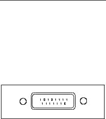
Transceiver Front Panel
The Transceiver front panel contains the 15-pin AUI (Attachment Unit Interface) connector. The AUI 15-pin D subminiature male connector conforms to IEEE 802.3 and Ethernet Version 2.0 requirements. The shell of the connector is not insulated from the transceiver case, thereby providing optimal shielding and minimizing radiation.
Figure 2 shows the AUI connector on the Transceiver front panel.
Figure 2. Transceiver Front Panel
Page 6

Transceiver Rear Panel
The Transceiver rear panel contains the Fiber Optic (SMA, ST, or FC) connectors and four indicators (LEDs). The LEDs provide status for:
■Fiber link (transmit and receive)
■SQE Test
■Ports
The LEDs can be On, Off, or Blinking. The number of consecutive blinks before a longer pause on the STA (status) LED indicates the type of failure detected on the link. For ease of interpretation, a table is printed on the top panel of the transceiver to briefly describe the type of failure. This table is also repeated in greater detail in the Troubleshooting section later in this manual.
Refer to the Troubleshooting section later in this manual for a description of the LED blink sequences.
Page 7
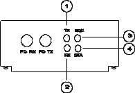
Figure 3 shows the rear panel on the 10BASE-FB Transceiver. Table 2 provides a description of the LEDs.
Figure 3. Transceiver Rear Panel
Page 8
Loading...