


 Loading...
3com 5203R-CSE, 5203R-CSDI, 5203R-CSD, 5203R-CSIX, 4203R-CSE Edge Router Module Installation Guide for Token Ring
...Edge Router Module
Installation Guide
for
Token Ring
Document Number 17-00677-2
Printed April 1996
Model Numbers:
5203R-CSE
5203R-CSDI
5203R-CSD
5203R-CSIX
4203R-CSE
4203R-CSDI
4203R-CSD
4203R-CSIX
3Com Corporation
118 Turnpike Road
Southborough, MA 01772-1886
U.S.A.
(508) 460-8900
FAX (508) 460-8950

Federal Communications Commission
Notice
This equipment has been tested and found to comply with the limits for a Class A digital device, pursuant to Part 15 of the FCC Rules. These limits are designed to provide reasonable protection against harmful interference when the equipment is operated in a commercial environment. This equipment generates, uses, and can radiate radio frequency energy and, if not installed and used in accordance with the instruction manual, may cause harmful interference to radio communications.Operationofthis equipment in a residential area is likely to cause harmful interference, in which case you must correct the interference at your own expense.
Canadian Emissions Requirements
This Class A digital apparatus meets all requirements of the Canadian Interference-Causing Equipment Regulations.
Cet appareil numérique de la classe A respecte toutes lesexigences du Règlement sur le matériel brouilleur du Canada.
VDE Class B Compliance
Hiermit wird bescheinigt, dass der 5203R-CSE, 5203R-CSDI, 5203R-CSD, 5203R-CSIX, 4203R-CSE, 4203R-CSDI, 4203R-CSD, 4203R-CSIX in Üebereinstimmung mit den Bestimmungen der Vfg 243/1991 funkentstöert ist.
Der Deutschen Bundespost wurde das Inverkehrbringen dieses Geraetes angezeigt und die Berechtigung zur Üeberprüefung der Serie auf Einhaltung der Bestimmungen eingeräeumt.
Einhaltung mit betreffenden Bestimmugen kommt darauf an, dass geschirmte Ausfuehrungen gebraucht werden. Fuer die Beschaffung richtiger Ausfuehrungen ist der Betreiber verantwortlich.
This is to certify that model numbers 5203R-CSE, 5203R-CSDI, 5203R-CSD, 5203R-CSIX, 4203R-CSE, 4203R-CSDI, 4203R-CSD, 4203R-CSIX are shielded against radio interference in accordance with the provisions of Vfg 243/1991.
The German Postal Services have been advised that this equipment is being placed on the market and that they have been given the right to inspect the series for compliance with regulations.
Compliance with applicable regulations depends on the use of shielded cables. The user is responsible for procuring the appropriate cables.
EN55022/CISPR22 Compliance
This equipment conforms to the Class A emissions limits for a digital device as defined by EN55022 (CISPR22).
VCCI Class 1 Compliance
This equipment is in the 1st Class category (information equipment to be used in commercial or industrial areas) and conforms to the standards set by the Voluntary Control Council for Interference by Information Technology Equipment aimed at preventing radio interference in commercial or industrial areas.
Consequently, when the equipment is used in a residential area or in an adjacent area, radio interference may be caused to radio and TV receivers, and so on.
Read the instructions for correct handling.
Fiber Cable Classification Notice
Use this equipment only with fiber cable classified by Underwriters Laboratories as to fire and smoke characteristics in accordance with Section 770-2(b) and Section 725-2(b) of the National Electrical Code.
UK General Approval Statement
The ONcore Switching Hub, ONline System Concentrator, and ONsemble StackSystem Hub are manufactured to the International Safety Standard EN 60950 and are approved in the UK under the General Approval Number NS/G/12345/J/100003 for indirect connection to the public telecommunication network.
Disclaimer
The information in this document is subject to change without notice and should not be construed as a commitment by 3Com Corporation. 3Com Corporation assumes no responsibility for any errors that may appear in this document.
Copyright Statement
© 1996 by 3Com Corporation. Printed in U.S.A. All rights reserved. The information contained herein is the exclusive and confidential property of 3Com Corporation. No part of this manual may be disclosed or reproduced in whole or in part without permission from 3Com Corporation.
Trademarks
Because of the nature of this material, numerous hardware and software products are mentioned by name. In most, if not all cases, these product names are claimed as trademarks by the companies that manufacture the products. It is not our intent to claim these names or trademarks as our own.
ONcore, and ONsemble are registered trademarks of 3Com Corporation.
ii Token Ring Edge Router Module Installation Guide
OpenHub, ONdemand, ONline, StackJack, and StackSystem are trademarks of 3Com Corporation.
The 3Com Multichannel Architecture Communications System is registered under U.S. Patent Number 5,301,303.
Apollo is a registered trademark of Apollo Computer, Incorporated.
AppleTalk is a registered trademark of Apple Computer, Incorporated.
Banyan and VINES are registered trademarks of Banyan Systems Inc.
Cisco and Cisco Systems are registered trademarks of Cisco Systems, Inc.
AGS+, ASM, IGRP, Internetworking Operating System, IOS, MGS, and UniverCD are trademarks of Cisco Systems, Inc.
DECnet is a trademark of Digital Equipment Corporation.
IBM is a registered trademark of International Business Machines.
NetBIOS is a trademark of Micro Computer Systems, Inc.
NetWare and Novell are registered trademarks of Novell, Incorporated.
IPX is a trademark of Novell, Incorporated.
Restricted Rights
Use, duplication, or disclosure by the Government is subject to restrictions as set forth in subparagraph (c)(1) (ii) of the Rights in Technical Data and Computer Software clause at
DFARS 252.227-7013.
Token Ring Edge Router Module Installation Guide iii
Contents
How to Use This Guide
Audience . . . . . . . . . . . . . . . . . . . . . . . . . . . . . . . . . . . . . . . . . . . . . . . . . xv Structure of This Guide . . . . . . . . . . . . . . . . . . . . . . . . . . . . . . . . . . . . . . .xvi Document Conventions . . . . . . . . . . . . . . . . . . . . . . . . . . . . . . . . . . . . . xvii Related Documents . . . . . . . . . . . . . . . . . . . . . . . . . . . . . . . . . . . . . . . . xviii
3Com Documents . . . . . . . . . . . . . . . . . . . . . . . . . . . . . . . . . . . . . . .xix Cisco Systems Documents . . . . . . . . . . . . . . . . . . . . . . . . . . . . . . . . . xx Reference Documents . . . . . . . . . . . . . . . . . . . . . . . . . . . . . . . . . . . . . xx
Chapter 1 — Introduction
Product Overview . . . . . . . . . . . . . . . . . . . . . . . . . . . . . . . . . . . . . . . . . . 1-1
Router Module Operation . . . . . . . . . . . . . . . . . . . . . . . . . . . . . . . . . 1-2
Router Module Architecture . . . . . . . . . . . . . . . . . . . . . . . . . . . . . . . 1-3
Router Module Features . . . . . . . . . . . . . . . . . . . . . . . . . . . . . . . . . . . . . 1-5
Software Options . . . . . . . . . . . . . . . . . . . . . . . . . . . . . . . . . . . . . . . 1-5
Topology Switching Capability . . . . . . . . . . . . . . . . . . . . . . . . . . . . . 1-8
Network Reliability . . . . . . . . . . . . . . . . . . . . . . . . . . . . . . . . . . . . . . 1-8
IOS Router Software Updates . . . . . . . . . . . . . . . . . . . . . . . . . . . . . 1-10
Memory Upgrades . . . . . . . . . . . . . . . . . . . . . . . . . . . . . . . . . . . . . 1-10
Chapter2—InstallingandConfiguringtheEdgeRouterModule
Installation Overview . . . . . . . . . . . . . . . . . . . . . . . . . . . . . . . . . . . . . . . 2-2 Precautionary Procedures . . . . . . . . . . . . . . . . . . . . . . . . . . . . . . . . . . . . 2-3 Troubleshooting Installation Problems . . . . . . . . . . . . . . . . . . . . . . . . 2-3 Quick Installation . . . . . . . . . . . . . . . . . . . . . . . . . . . . . . . . . . . . . . . . . . 2-4 Unpacking Procedures . . . . . . . . . . . . . . . . . . . . . . . . . . . . . . . . . . . . . . 2-5 Verifying the Jumper Plug Positions . . . . . . . . . . . . . . . . . . . . . . . . . . . . 2-6 Verifying Jumper Plug Positions on the Engine . . . . . . . . . . . . . . . . . 2-6 Configuring the Router Module in an Unmanaged Hub . . . . . . . . . . . . . 2-7
Configuring the ONline Carrier in an Unmanaged Hub . . . . . . . . . . . 2-8
Edge Router Module Installation Guide for Token Ring v
Locating the ONline Carrier DIP Switches . . . . . . . . . . . . . . . . . . 2-8 Selecting a Backplane Network . . . . . . . . . . . . . . . . . . . . . . . . . . 2-9
Setting the Ring Speed . . . . . . . . . . . . . . . . . . . . . . . . . . . . . . . 2-10
Isolating the Router Module . . . . . . . . . . . . . . . . . . . . . . . . . . . 2-11 Installing the Router Module . . . . . . . . . . . . . . . . . . . . . . . . . . . . . . . . 2-11
Installing the ONline Edge Router Module . . . . . . . . . . . . . . . . . . . . 2-11
Installing the Edge Router Module . . . . . . . . . . . . . . . . . . . . . . 2-11 Re-initializing the Backplane . . . . . . . . . . . . . . . . . . . . . . . . . . . 2-12 Installing the ONsemble Edge Router Module . . . . . . . . . . . . . . . . . 2-13 Before You Install the ONsemble Edge Router Module . . . . . . . 2-13 Installing the ONsemble Edge Router Module in a Hub Stack . . 2-14 Configuring the Router Module in a Managed Hub . . . . . . . . . . . . . . . 2-17
Managed Configuration Overview . . . . . . . . . . . . . . . . . . . . . . . . . 2-18
Attaching a Management Terminal . . . . . . . . . . . . . . . . . . . . . . . . . 2-18 Attaching a Terminal to the Console Port of the Engine . . . . . . 2-19 Attaching a Terminal to the Auxiliary Port of the Engine . . . . . . 2-20 Attaching a Terminal to the Management Module . . . . . . . . . . 2-21
Configuring the Edge Router Module Engine . . . . . . . . . . . . . . . . . 2-22
Configuring the Edge Router Module Carrier . . . . . . . . . . . . . . . . . 2-22 Configuring the ONline Carrier in a Managed Hub . . . . . . . . . . 2-23 Configuring the ONsemble Carrier . . . . . . . . . . . . . . . . . . . . . . 2-24
Chapter 3 — Using the Edge Router Module
Showing the Router Module Configuration and Status . . . . . . . . . . . . . . 3-2
Showing the Engine Configuration and Status . . . . . . . . . . . . . . . . . 3-2 Showing the Carrier Configuration and Status . . . . . . . . . . . . . . . . . 3-2
Using the SHOW MODULE Command . . . . . . . . . . . . . . . . . . . . 3-2 Using the SHOW PORT Command . . . . . . . . . . . . . . . . . . . . . . . 3-4 Monitoring Router Module Operation . . . . . . . . . . . . . . . . . . . . . . . . . . 3-5 Monitoring Engine LEDs . . . . . . . . . . . . . . . . . . . . . . . . . . . . . . . . . . 3-5 Monitoring the ONsemble Carrier LEDs . . . . . . . . . . . . . . . . . . . . . . . 3-8
Testing the LEDs . . . . . . . . . . . . . . . . . . . . . . . . . . . . . . . . . . . . . 3-8
Interpreting the Carrier LEDs . . . . . . . . . . . . . . . . . . . . . . . . . . . 3-10 Recovering a Lost Password . . . . . . . . . . . . . . . . . . . . . . . . . . . . . . . . . 3-22
Updating or Upgrading IOS Software . . . . . . . . . . . . . . . . . . . . . . . . . . 3-24
Revising IOS Software . . . . . . . . . . . . . . . . . . . . . . . . . . . . . . . . . . . 3-25 Using Flash Load Helper . . . . . . . . . . . . . . . . . . . . . . . . . . . . . . 3-25 Revising IOS Software Manually . . . . . . . . . . . . . . . . . . . . . . . . 3-26
vi Edge Router Module Installation Guide for Token Ring
Increasing IOS Software Memory . . . . . . . . . . . . . . . . . . . . . . . . . . 3-27
Replacing the Flash SIMM . . . . . . . . . . . . . . . . . . . . . . . . . . . . . 3-28
Replacing the Boot PROMs . . . . . . . . . . . . . . . . . . . . . . . . . . . . . . . 3-30
Increasing Operating Memory . . . . . . . . . . . . . . . . . . . . . . . . . . . . . . . 3-32
Base DRAM Memory Configuration . . . . . . . . . . . . . . . . . . . . . . . . 3-33
Allocation of Operating Memory . . . . . . . . . . . . . . . . . . . . . . . . . . 3-34
Adding DRAM SIMM Memory . . . . . . . . . . . . . . . . . . . . . . . . . . . . 3-35
Chapter 4 — Troubleshooting
Troubleshooting Startup Problems . . . . . . . . . . . . . . . . . . . . . . . . . . . . . 4-2
Troubleshooting Engine Problems . . . . . . . . . . . . . . . . . . . . . . . . . . . 4-2
Troubleshooting Mailbox Interface Problems . . . . . . . . . . . . . . . . . . . 4-2
Troubleshooting 3Com Carrier Problems . . . . . . . . . . . . . . . . . . . . . 4-3
Troubleshooting Network Connectivity Problems . . . . . . . . . . . . . . . . . . 4-3
Troubleshooting WAN Connectivity Problems . . . . . . . . . . . . . . . . . . . . . 4-4
Correcting Operating Malfunction . . . . . . . . . . . . . . . . . . . . . . . . . . . . . 4-5
Obtaining Technical Assistance . . . . . . . . . . . . . . . . . . . . . . . . . . . . . . . . 4-7
Appendix A — Product Specifications
General Specifications . . . . . . . . . . . . . . . . . . . . . . . . . . . . . . . . . . . . . . A-2
Electrical Specifications . . . . . . . . . . . . . . . . . . . . . . . . . . . . . . . . . . . . . . A-3
Router Module Capacities . . . . . . . . . . . . . . . . . . . . . . . . . . . . . . . . . . . A-3
Environmental Specifications . . . . . . . . . . . . . . . . . . . . . . . . . . . . . . . . . A-4
Mechanical Specifications . . . . . . . . . . . . . . . . . . . . . . . . . . . . . . . . . . . . A-4
Appendix B — Cabling Specifications
Console and Auxiliary Port Cables . . . . . . . . . . . . . . . . . . . . . . . . . . . . . |
B-1 |
Console Port Pinouts . . . . . . . . . . . . . . . . . . . . . . . . . . . . . . . . . . . . |
B-2 |
Console Port (DTE) . . . . . . . . . . . . . . . . . . . . . . . . . . . . . . . . . . . |
B-2 |
Mini-DIN to DB-25 Modem Cable . . . . . . . . . . . . . . . . . . . . . . . . |
B-3 |
Auxiliary Port Pinouts . . . . . . . . . . . . . . . . . . . . . . . . . . . . . . . . . . . . |
B-4 |
Auxiliary Port (DTE) . . . . . . . . . . . . . . . . . . . . . . . . . . . . . . . . . . . |
B-4 |
Mini-DIN to DB-25 Modem Cable . . . . . . . . . . . . . . . . . . . . . . . . |
B-5 |
3Com OpenHub Management Cable . . . . . . . . . . . . . . . . . . . . . . . . |
B-6 |
DB-25 Null Modem Cable . . . . . . . . . . . . . . . . . . . . . . . . . . . . . . . . . |
B-7 |
Serial Port Cable Assemblies and Pinouts . . . . . . . . . . . . . . . . . . . . . . . . |
B-7 |
Edge Router Module Installation Guide for Token Ring vii
EIA-530 DTE Synchronous Serial Cable Pinouts . . . . . . . . . . . . . . . . . B-8 RS-232 DTE and DCE Serial Cable Assembly and Pinouts (DB-25) . . B-10
RS-449 DTE and DCE Serial Cable Assembly and Pinouts (DB-37) . . B-13
V.35 DTE and DCE Serial Cable Assembly and Pinouts (Winchester-Type 34-Pin) . . . . . . . . . . . . . . . . . . . . . . . . . . . . . . . . . . . . . . . . . . . . . . B-17
X.21 DTE and DCE Serial Cable Pinouts (DB-15) . . . . . . . . . . . . . . . B-21
Appendix C — Virtual Configuration Register
Virtual Configuration Register Bit Definitions . . . . . . . . . . . . . . . . . . . . . C-2
Boot Field . . . . . . . . . . . . . . . . . . . . . . . . . . . . . . . . . . . . . . . . . . . . . C-3
Setting Boot Field Values . . . . . . . . . . . . . . . . . . . . . . . . . . . . . . C-3
Default Boot Filenames . . . . . . . . . . . . . . . . . . . . . . . . . . . . . . . . C-4
Break Function . . . . . . . . . . . . . . . . . . . . . . . . . . . . . . . . . . . . . . . . . C-6
Internet Broadcast Address . . . . . . . . . . . . . . . . . . . . . . . . . . . . . . . . C-6
Engine Management Terminal Baud Rate . . . . . . . . . . . . . . . . . . . . . C-7
Bootload Failure Response . . . . . . . . . . . . . . . . . . . . . . . . . . . . . . . . C-8
NVRAM Disable . . . . . . . . . . . . . . . . . . . . . . . . . . . . . . . . . . . . . . . . C-8
Changing Configuration Register Settings . . . . . . . . . . . . . . . . . . . . . . . C-8
Enabling Booting From Flash Memory . . . . . . . . . . . . . . . . . . . . . . . . . . . C-9
Appendix D — Bootstrap Program
Entering the Bootstrap Program . . . . . . . . . . . . . . . . . . . . . . . . . . . . . . . D-1
Available Bootstrap Commands . . . . . . . . . . . . . . . . . . . . . . . . . . . . . . . D-2
Running Diagnostics . . . . . . . . . . . . . . . . . . . . . . . . . . . . . . . . . . . . . . . . D-6
Appendix E — Technical Support
On-line Technical Support . . . . . . . . . . . . . . . . . . . . . . . . . . . . . . . . . . . |
E-1 |
Email Technical Support . . . . . . . . . . . . . . . . . . . . . . . . . . . . . . . . . . |
E-2 |
World Wide Web Site . . . . . . . . . . . . . . . . . . . . . . . . . . . . . . . . . . . . |
E-2 |
Support from Your Network Supplier . . . . . . . . . . . . . . . . . . . . . . . . . . . |
E-2 |
Support from 3Com . . . . . . . . . . . . . . . . . . . . . . . . . . . . . . . . . . . . . . . . |
E-3 |
Returning Products for Repair . . . . . . . . . . . . . . . . . . . . . . . . . . . . . . . . . |
E-4 |
Accessing the 3Com MIB . . . . . . . . . . . . . . . . . . . . . . . . . . . . . . . . . . . . |
E-4 |
3Com Technical Publications . . . . . . . . . . . . . . . . . . . . . . . . . . . . . . . . . |
E-5 |
Index
viii Edge Router Module Installation Guide for Token Ring
Figures
Figure 1-1. |
Typical Edge Router Module Functions . . . . . . . . |
. . . . . . 1-2 |
Figure 1-2. |
Edge Router Module Application in the ONline, ONsemble, |
|
|
and ONcore Hubs |
1-4 |
Figure 1-3. |
Network Reliability Configuration . . . . . . . . . . . . |
. . . . . . 1-9 |
Figure 2-1. |
Installing and Configuring the Edge Router Module . . . . 2-2 |
|
Figure 2-2. |
Engine Jumper Plug Locations . . . . . . . . . . . . . . . |
. . . . . . 2-6 |
Figure 2-3. |
ONline Carrier DIP Switch Location . . . . . . . . . . . |
. . . . . . 2-8 |
Figure 2-4. |
Inserting a Module into an ONline Hub . . . . . . . . |
. . . . . 2-12 |
Figure 2-5. |
Typical Hub Installation . . . . . . . . . . . . . . . . . . . . |
. . . . . 2-14 |
Figure 2-6. |
Connecting Power to the Edge Router Module . . |
. . . . . 2-15 |
Figure 2-7. |
Reconnected StackJack Cable . . . . . . . . . . . . . . . |
. . . . . 2-15 |
Figure 2-8. |
Connecting the New StackJack Cable . . . . . . . . . |
. . . . . 2-16 |
Figure 2-9. |
Hub ID Switch Location . . . . . . . . . . . . . . . . . . . . |
. . . . . 2-17 |
Figure 2-10. |
Attaching a Terminal to the Engine Console Port |
. . . . . 2-19 |
Figure 2-11. |
Attaching a Terminal to the Engine Auxiliary Port |
. . . . . 2-20 |
Figure 2-12. |
Terminal Connections to the NMM and Edge Router |
|
|
Module Console Ports . . . . . . . . . . . . . . . . . . . |
. . . . . 2-21 |
Figure 3-1. |
Edge Router Module Engine LEDs . . . . . . . . . . . . |
. . . . . . 3-6 |
Figure 3-2. |
Edge Router Module ONsemble Carrier LEDs . . . . |
. . . . . . 3-8 |
Figure 3-3. |
IOS Software Flash SIMM . . . . . . . . . . . . . . . . . . |
. . . . . 3-24 |
Figure 3-4. |
Removing and Replacing a SIMM — Flash SIMM Shown 3-29 |
|
Figure 3-5. |
Boot PROM Locations . . . . . . . . . . . . . . . . . . . . . |
. . . . . 3-30 |
Figure 3-6. |
DRAM Operating Memory on the Router Module Engine 3-33 |
|
Figure B-1. |
Mini-DIN Serial Port Pinouts . . . . . . . . . . . . . . . . |
. . . . . . B-2 |
Figure B-2. |
EIA-530 Cable Assembly . . . . . . . . . . . . . . . . . . . |
. . . . . . B-8 |
Figure B-3. |
RS-232 Serial Cable Assembly . . . . . . . . . . . . . . . |
. . . . . B-10 |
Figure B-4. |
RS-449 Serial Cable Assembly . . . . . . . . . . . . . . . |
. . . . . B-14 |
Figure B-5. |
V.35 Serial Cable Assembly . . . . . . . . . . . . . . . . . |
. . . . . B-17 |
Figure B-6. |
X.21 Cable Assembly . . . . . . . . . . . . . . . . . . . . . |
. . . . . B-21 |
Edge Router Module Installation Guide for Token Ring ix
Tables
Table 1-1. Software Feature Sets . . . . . . . . . . . . . . . . . . . . . . . . . . . 1-6 Table 1-2. Memory Configurations . . . . . . . . . . . . . . . . . . . . . . . . . 1-10
Table 2-1. Quick Installation Steps . . . . . . . . . . . . . . . . . . . . . . . . . . 2-4
Table 2-2. Default Engine Jumper Plug Settings . . . . . . . . . . . . . . . . 2-7 Table 2-3. ONline Carrier DIP Switch Settings . . . . . . . . . . . . . . . . . . 2-9 Table 2-4. ONline Slot Assignments for Multiple Rings . . . . . . . . . . 2-10 Table 3-1. Interpreting Router Module Engine LEDs . . . . . . . . . . . . . 3-7
Table 3-2. Interpreting the Power On LED . . . . . . . . . . . . . . . . . . . 3-10
Table 3-3. Interpreting the Primary LED . . . . . . . . . . . . . . . . . . . . . 3-11
Table 3-4. Interpreting the BUPS LED . . . . . . . . . . . . . . . . . . . . . . . 3-12 Table 3-5. Interpreting the System LED . . . . . . . . . . . . . . . . . . . . . . 3-13
Table 3-6. Interpreting the Beacon LED . . . . . . . . . . . . . . . . . . . . . 3-15 Table 3-7. Interpreting the Speed LED . . . . . . . . . . . . . . . . . . . . . . 3-15
Table 3-8. Interpreting Port LEDs . . . . . . . . . . . . . . . . . . . . . . . . . . 3-16
Table 3-9. Interpreting Stack In and Stack Out LEDs . . . . . . . . . . . . 3-18 Table 3-10. Interpreting the Isolated LED . . . . . . . . . . . . . . . . . . . . . 3-21
Table 3-11. Memory Allocation . . . . . . . . . . . . . . . . . . . . . . . . . . . . 3-34
Table 4-1. Troubleshooting Malfunctions . . . . . . . . . . . . . . . . . . . . . 4-5 Table B-1. Console Port Pinout Functions (DTE) . . . . . . . . . . . . . . . . B-3
Table B-2. 3Com OpenHub Management Cable Pinouts. . . . . . . . . . B-3
Table B-3. Auxiliary Port Pinout Functions (DTE) . . . . . . . . . . . . . . . . B-5 Table B-4. 3Com OpenHub Management Cable Pinouts. . . . . . . . . . B-6
Table B-5. EIA-530 DTE Cable Pinouts (DB-60 to DB-25). . . . . . . . . . B-8
Table B-6. RS-232 DTE Cable Pinouts (DB-60 to DB-25) . . . . . . . . . B-11 Table B-7. RS-232 DCE Cable Pinouts (DB-60 to DB-25) . . . . . . . . . B-12 Table B-8. RS-449 DTE Cable Pinouts (DB-60 to DB-37) . . . . . . . . . B-14
Table B-9. RS-449 DCE Cable Pinouts (DB-60 to DB-37) . . . . . . . . . B-16 Table B-10. V.35 DTE Cable Pinouts . . . . . . . . . . . . . . . . . . . . . . . . . B-18 Table B-11. V.35 DCE Cable Pinouts. . . . . . . . . . . . . . . . . . . . . . . . . B-19 Table B-12. X.21 DTE Cable Pinouts (DB-60 to DB-15) . . . . . . . . . . . B-22 Table B-13. X.21 DCE Cable Pinouts (DB-60 to DB-15) . . . . . . . . . . . B-23 Table C-1. Virtual Configuration Register Bit Values . . . . . . . . . . . . . C-2
Edge Router Module Installation Guide for Token Ring xi
Table C-2. Boot Field Values (Configuration Register Bits 00 to 03) . . C-3
Table C-3. Default Boot Filenames . . . . . . . . . . . . . . . . . . . . . . . . . . C-5
Table C-4. Broadcast Address Destination Settings . . . . . . . . . . . . . . C-7 Table C-5. Engine Management Terminal Baud Rate Settings . . . . . . C-7 Table D-1. Command Options . . . . . . . . . . . . . . . . . . . . . . . . . . . . . D-5
xii Edge Router Module Installation Guide for Token Ring

How to Use This
Guide
This guide describes how to install and use the 3Com® Edge Router Module in the following 3Com products:
ONline™ System Concentrator
ONsemble™ Hubs
ONcore® Switching Hub
This guide also provides troubleshooting suggestions in case a problem arises with the module.
Audience
This guide is intended for the following trained service personnel at your site:
Network manager or administrator
Hardware installer
Edge Router Module Installation Guide for Token Ring xiii

Structure of This Guide
This guide contains the following chapters:
Chapter 1, Introduction – Provides an introduction to the Edge Router
Module.
Chapter 2, Installing and Configuring the Edge Router Module –
Explains how to configure and install the module in each of the 3Com hub products.
Chapter 3, Using the Edge Router Module – Explains how to perform basic tasks that are helpful when using the router module.
Chapter 4, Troubleshooting – Provides troubleshooting information to correct problems that arise during installation and operation.
Appendix A, Product Specifications – Contains general product specifications for the Edge Router Module.
Appendix B, Cabling Specifications – Contains cabling specifications for the Edge Router Module.
Appendix C, Virtual Configuration Register – Describes the router module engine virtual configuration register and provides procedures for modifying the virtual configuration register settings.
Appendix D, Bootstrap Program – Summarizes the router module engine bootstrap diagnostic tests and command options.
Appendix E, Technical Support – Lists the various methods for contacting the 3Com technical support organization and for accessing other product support services.
Index
xiv Edge Router Module Installation Guide for Token Ring

Document Conventions
The following document conventions are used in this guide:
Convention |
Indicates |
Example |
|
|
|
|
|
Courier text |
User input |
In the Agent Information |
|
|
|
|
Form, enter MIS in the New |
|
|
|
Contact field. |
|
|
|
|
|
|
System output |
After pressing the Apply |
|
|
|
button, the system displays the |
|
|
|
message Transmitting |
|
|
|
data. |
|
|
|
|
Bold command |
Path names |
Before you begin, read the |
|
string |
|
readme.txt file located in |
|
|
|
|
/usr/snm/agents. |
|
|
|
|
Text in angled |
User-substituted |
In the command above, |
|
brackets Italic text |
identifiers |
substitute <rem_name> with |
|
in braces |
|
the name of the remote |
|
|
|
|
machine.Use the following |
|
|
|
command to show port details: |
|
|
|
SHOW PORT {slot.all} VERBOSE |
|
|
|
|
Italics |
Text emphasis, |
Ensure that you press the Apply |
|
|
|
document titles |
button after you add the new |
|
|
|
search parameters. |
|
|
|
|
Edge Router Module Installation Guide for Token Ring xv

Convention |
Indicates |
Example |
|
|
|
Note: |
A Note. The |
Note: Use STP lobe |
|
information is |
cables for your system. |
|
important |
|
|
|
|
Caution: |
A Caution. A |
Caution: Do not put |
|
condition may |
your installation |
|
damage |
diskettes on a |
|
software or |
magnetic surface. This |
|
hardware |
may damage the |
|
|
diskettes. |
|
|
|
Warning: |
A Warning. A |
Warning: Wear eye |
|
condition may |
protection when |
|
threaten |
performing these |
|
personal safety |
maintenance |
|
|
procedures. |
|
|
|
Related Documents
This section providesinformation on supporting documentation, including:
3Com Documents
Ciscoä Systems Documents
Reference Documents
xvi Edge Router Module Installation Guide for Token Ring
3Com Documents
The following documents provide additional information on 3Com products:
ONline Token Ring Carrier Assembly and Configuration Guide — Provides information on assembling and configuring the ONline Token Ring Carrier.
ONsemble Token Ring Carrier Assembly and Configuration Guide —
Provides information on assembling and configuring the ONsemble Token
Ring Carrier.
ONcore Token Ring Carrier Assembly and Configuration Guide — Provides information on assembling and configuring the ONcore Token Ring Carrier.
ONline System Concentrator Installation and Operation Guide — Provides information on the installation, operation, and configuration of the ONline System Concentrator. This guide also describes the principal features of the
ONline Fault-Tolerant Controller Module.
ONcore Switching Hub Installation and Operation Guide — Provides information on the installation, operation, and configuration of the ONcore
Switching Hub. This guide also describes the principal features of the ONcore Fault-Tolerant Controller Module.
ONsemble StackSystem Token Ring Hub Installation and Operation Guide
— Provides information on the installation, operation, and configuration of the ONsemble StackSystem Token Ring Hub. This guide also describes the principal features of the ONsemble Fault-Tolerant Controller Module.
ONline, ONcore, and ONsemble Token Ring Hub Management Module
User’s Guides — Provide information on the Management Module’s operation, installation, and configuration. These guides also describe the software commands associated with the Management Module.
For a complete list of 3Com documents or to order 3Com documents, contact your 3Com representative.
Edge Router Module Installation Guide for Token Ring xvii
Cisco Systems Documents
A Cisco Systems UniverCD CD ROM disk is shipped with the router module. The disk provides an online version of the comprehensive Cisco Systems documentation set. To order additional copies of UniverCD disk, contact your 3Com representative and order Part Number:
17-00138-CD (CD-ROM documentation set)
A complete, multi-volume Cisco Systems printed documentation set is available for use with the Edge Router Module. Contact your 3Com representative and order Part Number:
17-00138-MS (Manual documentation set)
Reference Documents
The following documents supply related background information:
Case, J., Fedor, M., Scoffstall, M., and J. Davin, The Simple Network Management Protocol, RFC 1157, University of Tennessee at Knoxville, Performance Systems International and the MIT Laboratory for Computer
Science, May 1990.
Rose, M., and K. McCloghrie, Structure and Identification of
Management Information for TCP/IP-based Internets, RFC 1155, Performance Systems International and Hughes LAN Systems, May 1990.
xviii Edge Router Module Installation Guide for Token Ring

1 Introduction
This chapter provides an introduction to the 3Comâ Edge Router Module.
This chapter contains the following sections:
Product Overview
Router Module Features
Product Overview
The Edge Router Module (router module) is a serial port-to-token ring LAN interconnect module jointly developed by 3Com Corporation and Ciscoä
Systems, Inc.
This section provides information on the following topics:
Router Module Operation
Router Module Architecture
Introduction 1 - 1

Router Module Operation
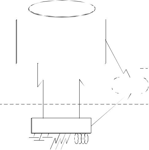
The router module (Figure 1-1) is designed to:
Connect corporate networks and increase wide area connectivity.
Support both synchronous and asynchronous routing over serial links using one local area network (LAN) and up to three wide area network (WAN) connections.
Provide flexible networking connections in multiprotocol environments.
Sit at the network’s logical and physical edge, either at a remote site or central facility.
Edge Router Module
Console Port
Auxiliary
Port
Network |
|
|
|
|
|
|
|
Token Ring LAN |
|
Backplane |
|
|
|
|
|
|
|
|
|
|
|
|
|
|
High Speed
WAN Port
High Speed
WAN Port
Figure 1-1. Typical Edge Router Module Functions
1 - 2 Edge Router Module Installation Guide for Token Ring
The router module runs Cisco standard software and fully interoperates with the:
3Com ONlineä Ethernet Router Module
Cisco local and remote router servers, such as the AGS+ä, MGSä, and the Cisco 3000, 4000, 4500, and 7000 series.
Router Module Architecture
Each router module consists of two components:
Engine Module - Provides Token Ring-to-WAN port connections.
Carrier Module - Provides connections to one of three 3Com switching hub products.
The engine mounts to one of three carrier types to form an Edge Router Module for the ONlineä, ONsembleâ, or ONcoreâ hub products.
The architecture of each Edge Router Module type is illustrated in Figure 1-2.
Introduction 1 - 3

ONline
System Concentrator
ONlineCarrier
Edge Router Module
Engine
Edge Router Module
Engine
ONcore
Switching Hub
ONcore Carrier
ONsemble
StackSystem Hub
ONsemble Carrier
Edge Router Module
Engine
Figure 1-2. Edge Router Module Application in the ONline, ONsemble, and ONcore Hubs
1 - 4 Edge Router Module Installation Guide for Token Ring

Router Module Features
This section describes the major features of the router module, including:
Software Options
Topology Switching Capability
Network Reliability
IOS Router Software Updates
Memory Upgrades
Software Options
The router module provides a choice of four software feature sets:
IP/IPX
Desktop
Desktop plus IBM
Enterprise
Introduction 1 - 5
The components which make up the software feature sets are listed in Table 1-1.
Table 1-1. Software Feature Sets
Feature |
|
|
Features Included per Feature Set |
||
|
|
|
|
|
|
|
|
|
Desktop plus |
|
|
Category |
IP/IPX |
Desktop |
Enterprise |
||
|
|
IBM |
|||
|
|
|
|
|
|
|
|
|
|
|
|
LAN Support |
IP, |
IP, Bridging, |
IP, Bridging, LAN |
IP, Bridging, LAN |
|
|
|
Bridging, |
LAN |
Extension, Host |
Extension, Host |
|
|
LAN |
Extension, |
Software, |
Software, Novell |
|
|
Extension, |
Host |
Novell IPX, |
IPX, DECnet IV, |
|
|
Host |
Software, |
DECnet IV, |
AppleTalk Phase 1 |
|
|
Software, |
Novell IPX, |
AppleTalk Phase |
and 2, DECnet V, |
|
|
Novell® |
DECnet™ IV, |
1 and 2 |
XNS, Banyan |
|
|
IPX™ |
Appletalk® |
|
VINES™, OSI, |
|
|
|
Phase 1 |
|
Apollo® Domain |
|
|
|
and 2 |
|
|
|
|
|
|
|
|
WAN Serial |
Dual Synchronous Ports, Single Asynchronous Auxiliary Port |
||||
Support |
|
|
|
|
|
|
|
|
|||
WAN Services |
HDLC, PPP, X.25, Frame Relay, SMDS |
|
|||
|
|
||||
WAN |
Header and link compression, dial-on-demand, dial backup, |
||||
Optimization |
bandwidth-on-demand, custom and priority queuing, access lists, |
||||
|
|
access security |
|
|
|
|
|
|
|
||
IP Routing |
RIP, IGRP™, Enhanced IGRP, OSPF, BGP, EGP, |
RIP, IGRP, |
|||
|
|
PIM |
|
|
Enhanced IGRP, |
|
|
|
|
|
OSPF, BGP, EGP, |
|
|
|
|
|
PIM, ES-IS, IS-IS |
|
|
|
|
|
|
1 - 6 Edge Router Module Installation Guide for Token Ring
Table 1-1. Software Feature Sets (Continued)
|
|
|
Features Included per Feature Set |
||
Feature |
|
|
|
|
|
|
|
|
Desktop plus |
|
|
Category |
IP/IPX |
Desktop |
Enterprise |
||
|
|
IBM |
|||
|
|
|
|
|
|
|
|
|
|
|
|
IBM Support |
|
|
Remote |
Remote |
|
|
|
|
|
source-route |
source-route |
|
|
|
|
bridging, proxy, |
bridging, proxy, |
|
|
|
|
explorer, |
explorer, local |
|
|
|
|
local acknowl- |
acknowledgment, |
|
|
|
|
edgment, SNA |
SNA local LU |
|
|
|
|
local LU address |
address |
|
|
|
|
prioritizing, |
prioritizing, |
|
|
|
|
administrative |
administrative |
|
|
|
|
filtering, |
filtering, NetBIOS |
|
|
|
|
NetBIOS™ name |
name caching, |
|
|
|
|
caching, |
NetBIOS access |
|
|
|
|
NetBIOS access |
control filtering, |
|
|
|
|
control filtering |
serial tunneling |
|
|
|
|
|
forSDLCTransport, |
|
|
|
|
|
SDLC link-level |
|
|
|
|
|
support, SDLLC, |
|
|
|
|
|
TG/COS, QLLC |
|
|
|
|
|
|
Network |
Autoinstall, SNMP, TELNET |
|
|
||
Management |
|
|
|
|
|
|
|
|
|
|
|
Protocol |
|
|
|
TELNET, LAT, |
|
Translation |
|
|
|
rlogin, TN3270, |
|
|
|
|
|
|
X.25 |
|
|
|
|
|
|
Introduction 1 - 7
Topology Switching Capability
The router module provides topology switching capability. Topology switching is the ability to switch the router module between token ring networks (rings) on the hub backplane using:
Network management module commands
Simple Network Management Protocol (SNMP)
You do not have to swap cables or move the router module to move the routing or bridging functions to a different network within the hub. You can enter a command through one of the 3Com management modules and the network change is made automatically.
Network Reliability
The router module provides the capability to implement several levels of reliability in your network:
By configuring the router module’s WAN and auxiliary ports in parallel, you can create up to three redundant serial links to protect your mission-critical applications.
You can configure up to two backup links to ensure that your applications are available if the primary link fails.
An example of the router module configured to provide reliability is shown in Figure 1-3. These serial links can also support load-balancing to augment the performance of your network.
1 - 8 Edge Router Module Installation Guide for Token Ring
|
|
|
|
|
Token Ring |
|
|
|||
|
|
|
|
|
|
|
|
|
|
|
|
|
|
|
|
|
|
|
|
|
|
|
|
|
|
|
|
|||||
|
|
|
|
Edge Router Module |
||||||
|
|
|
|
|
|
|
|
|
|
|
|
|
Console Port |
|
|
|
|
|
|
Aux Port |
|
|
|
|
|
|
|
|
|
|
|
|
Remote Site |
|
|
|
|
|
|
|
WAN Port |
|
|
|
|
|
|
|
|
|
|
|
|
WAN Port |
|
|
|
|
|
|
|
|
|
|
|
|
|
|
|
|
|
|
|
|
|
|
|||||||||||||||||||
|
|
|
|
|
|
|
|
|
|
|
|
|
|
|
|
|
|
|
|
|
|
|
|
|
|
|
|
|
|
|
|
|
|
|
|
|
|
|
|
|
|
|
|
|
|
|
|
|
|
|
|
|
|
|
||||||||
|
|
|
|
|
|
|
|
|
|
|
|
|
|
|
|
|
|
|
|
|
|
|
|
|
|
|
|
|
|
|
|
|
|
|
|
|
|
|
|
|
|
|
|
|
|
|
|
|
|
|
|
|
|
|
||||||||
|
|
|
|
|
|
|
|
|
|
|
|
|
|
|
|
|
|
|
|
|
|
|
|
|
|
|
|
|
|
|
|
|
|
|
|
|
|
|
|
|
|
|
|
|
|
|
|
|
|
|
|
|
|
|
||||||||
|
|
|
|
|
|
|
|
|
|
|
|
|
|
|
|
|
|
|
|
|
|
|
|
|
|
|
|
|
|
|
|
|
|
|
|
|
|
|
|
|
|
|
|
|
|
|
|
|
|
|
|
|
|
|
|
|
|
|
|
|
|
|
|
|
|
|
|
|
|
|
|
|
|
|
|
|
|
|
|
|
|
|
|
|
|
|
|
|
|
|
|
|
|
|
|
|
|
|
|
|
|
|
|
|
|
|
|
|
|
|
|
|
|
|
|
|
|
|
|
||||||
|
|
|
|
|
|
|
|
|
|
|
Primary |
|
|
|
|
Secondary |
|
Dial-Up |
|
|
|
|
|
Public |
||||||||||||||||||||||||||||||||||||||
|
|
|
|
|
|
|
|
|
|
|
|
|
|
|
|
|
|
|
|
Switched |
||||||||||||||||||||||||||||||||||||||||||
|
|
|
|
|
|
|
|
|
|
|
|
Link |
|
|
|
|
|
|
Link |
|
Link |
|
|
|
|
Telephone |
||||||||||||||||||||||||||||||||||||
|
|
|
|
|
|
|
|
|
|
|
|
|
|
|
|
|
|
|
|
|
|
|
|
|
|
|
|
|
|
|
|
|
|
|
|
|
|
|
|
|
|
|
|
|
|
|
|
|
|
|
|
|
|
Network |
||||||||
|
|
|
|
|
|
|
|
|
|
|
|
|
|
|
|
|
|
|
|
|
|
|
|
|
|
|
|
|
|
|
|
|
|
|
|
|
|
|
|
|
|
|
|
|
|
|
|
|
|
|
|
|
|
|
|
|
|
|
|
|
|
|
Main Site
Main Site Router
Main Site Network Connections
Figure 1-3. Network Reliability Configuration
Introduction 1 - 9
IOS Router Software Updates
The IOS software in the router module engine can be updated by purchasing field-upgradable software distribution kits. Update your module to the latest 3Com release of IOS software by downloading new code to flash memory on the module. New updates are shipped automatically as part of the 3Com 1-year Router Software Subscription Service or you can purchase it from 3Com as a single unit update.
You can also purchase an upgrade kit to upgrade your IP/IPX, Desktop, or Desktop plus IBMâ software to a version with an enhanced feature set.
Contact your 3Com reseller or 3Com Customer Support for more information and part numbers.
Memory Upgrades
The router module provides the capability to increase memory to meet the requirements of large routing table configurations.
Memory is configured on the router module to match the requirements of the selected IOS software feature set. Table 1-2 lists the base memory configurations for each software feature set.
Table 1-2. Memory Configurations
|
|
|
|
|
Feature Set |
|
Memory |
|
|
|
|
|
|
|
|
|
|
Desktop |
|
|
Type |
|
|
|
|
||
|
IP/IPX |
Desktop |
plus |
Enterprise |
||
|
|
|
||||
|
|
|
|
|
IBM |
|
|
|
|
|
|
|
|
IOS (Flash |
4 |
MB (expandable |
8 MB |
|
||
EPROM) |
to 8 MB) |
|
|
|||
|
|
|
|
|
|
|
Data (DRAM) |
4 |
MB (expandable to 16 MB) |
6 MB (expandable to 18 MB) |
|||
|
|
|
|
|
|
|
1 - 10 Edge Router Module Installation Guide for Token Ring

2 Installing and
Configuring the Edge
Router Module
This chapter contains the following sections:
Installation Overview
Precautionary Procedures
Quick Installation
Unpacking Procedures
Verifying Jumper Plug Positions
Configuring the Router Module in an Unmanaged Hub
Installing the Router Module
Configuring the Router Module in a Managed Hub
Note: The information and procedures presented in this chapter are to be used only by trained service personnel to install and maintain all models of the Edge Router Module.
Installing and Configuring the Edge Router Module 2 - 1
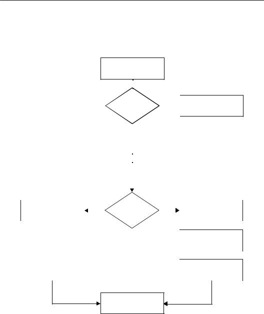
Installation Overview
The flowchart in Figure 2-1 identifies the steps that are required to install the router module in a managed hub and in an unmanaged hub.
Read Precautionary
Procedures
(page 2-3)
|
|
|
|
|
Experienced |
|
Yes |
Go to Quick Installation |
||||
|
|
|
|
|
|
(page 2-4) |
||||||
|
|
|
|
|
Installer? |
|
|
|
||||
|
|
|
|
|
|
|
|
|
|
|||
|
|
|
|
|
|
No |
|
|
|
|
|
|
|
|
|
|
|
|
|
|
|
|
|
||
|
|
|
|
|
|
|
|
|
|
|
||
|
|
|
|
|
Unpack the Module |
|
|
|
|
|
||
|
|
|
|
|
(page 2-5) |
|
|
|
|
|
||
|
|
|
|
|
|
|
|
|
|
|
|
|
|
|
|
|
|
|
|
|
|
|
|
|
|
|
|
|
|
|
Verify Jumper Plug |
|
|
|
|
|
||
|
|
|
|
|
Positions |
|
|
|
|
|
||
|
|
|
|
|
(page 2-6) |
|
|
|
|
|
||
|
|
|
|
|
|
|
|
|
|
|
Configure the Carrier |
|
|
|
|
|
|
|
|
|
|
|
|
||
|
|
|
|
|
Managed |
|
|
|
|
|||
Install the Module |
|
Yes |
|
|
No |
|
||||||
|
|
|
Using DIP Switches |
|||||||||
(page 2-11) |
|
|
|
Hub? |
|
|
|
|||||
|
|
|
|
|
|
(page 2-7) |
||||||
|
|
|
|
|
|
|
|
|
|
|
||
|
|
|
|
|
|
|
|
|
|
|
|
|
|
|
|
|
|
|
|
|
|
|
|
|
|
Configure the Engine |
|
|
|
|
|
|
|
|
|
Install the Module |
||
Using Cisco Commands |
|
|
|
|
|
|
|
|
|
|||
|
|
|
|
|
|
|
|
|
(page 2-11) |
|||
(page 2-22) |
|
|
|
|
|
|
|
|
|
|||
|
|
|
|
|
|
|
|
|
|
|
||
|
|
|
|
|
|
|
|
|
|
|
|
|
|
|
|
|
|
|
|
|
|
|
|
|
|
Configure |
the Carrier |
|
|
|
|
|
|
|
|
|
Configure |
the Engine |
Using NMM Commands |
|
|
|
|
|
|
|
|
|
Using Cisco Commands |
||
(page 2-22) |
|
|
|
|
|
|
|
|
|
(page 2-22) |
||
|
|
|
|
|
|
|
|
|
|
|
|
|
Installation Complete
Figure 2-1. Installing and Configuring the Edge Router Module
2 - 2 Edge Router Module Installation Guide for Token Ring
Loading...