


3Com Switch 4007
Getting Started Guide
http://www.3com.com/
Part No. 10013650
Published May 2000
3Com Corporation ■ 5400 Bayfront Plaza ■ Santa Clara, California ■ 95052-8145
Copyright © 2000, 3Com Corporation. All rights reserved. No part of this documentation may be reproduced in any form or by any means or used to make any derivative work (such as translation, transformation, or adaptation) without written permission from 3Com Corporation.
3Com Corporation reserves the right to revise this documentation and to make changes in content from time to time without obligation on the part of 3Com Corporation to provide notification of such revision or change.
3Com Corporation provides this documentation without warranty, term, or condition of any kind, either implied or expressed, including, but not limited to, the implied warranties, terms, or conditions of merchantability, satisfactory quality, and fitness for a particular purpose. 3Com may make improvements or changes in the product(s) and/or the program(s) described in this documentation at any time.
If there is any software on removable media described in this documentation, it is furnished under a license agreement included with the product as a separate document, in the hard copy documentation, or on the removable media in a directory file named LICENSE.TXT or !LICENSE.TXT. If you are unable to locate a copy, please contact 3Com and a copy will be provided to you.
UNITED STATES GOVERNMENT LEGEND
If you are a United States government agency, then this documentation and the software described herein are provided to you subject to the following:
All technical data and computer software are commercial in nature and developed solely at private expense. Software is delivered as “Commercial Computer Software” as defined in DFARS 252.227-7014 (June 1995) or as a “commercial item” as defined in FAR 2.101(a) and as such is provided with only such rights as are provided in 3Com’s standard commercial license for the Software. Technical data is provided with limited rights only as provided in DFAR 252.227-7015 (Nov 1995) or FAR 52.227-14 (June 1987), whichever is applicable. You agree not to remove or deface any portion of any legend provided on any licensed program or documentation contained in, or delivered to you in conjunction with, this User Guide.
Unless otherwise indicated, 3Com registered trademarks are registered in the United States and may or may not be registered in other countries.
3Com, CoreBuilder, and Transcend are registered trademarks, and the 3Com logo is a trademark, of 3Com Corporation. 3Com Facts is a service mark of 3Com Corporation.
Intel is a registered trademark of Intel Corporation.
Windows is a registered trademark of Microsoft Corporation.
UNIX is a registered trademark in the United States and other countries, licensed exclusively through X/Open Company, Ltd.
All other company and product names may be trademarks of the respective companies with which they are associated.

CONTENTS
|
|
|
|
|
|
2 |
SWITCH 4007 MODULES |
|
||
|
ABOUT THIS GUIDE |
|
|
|
||||||
|
|
|
|
Overview 19 |
|
|
|
|||
|
Conventions |
7 |
|
|
|
|
|
|
|
|
|
|
|
|
|
Switch Fabric Modules |
20 |
|
|||
|
Related Documentation |
8 |
|
|
|
|||||
|
|
|
9-port Gigabit Ethernet Switch Fabric |
20 |
||||||
|
Paper Documents |
9 |
|
|
|
|||||
|
|
|
|
24-port Gigabit Ethernet Switch Fabric |
20 |
|||||
|
Documents on CD-ROM 9 |
|
|
|||||||
|
|
|
Management Modules |
21 |
|
|||||
|
World Wide Web Site |
9 |
|
|
|
|||||
|
|
|
Fast Ethernet Modules |
22 |
|
|||||
|
3Com Facts Automated Fax Service |
10 |
|
|
||||||
|
|
20-port 100BASE-FX (MT-RJ) Fast Ethernet Layer 2 |
||||||||
|
Year 2000 Compliance |
10 |
|
|
||||||
|
|
|
Switching Module |
22 |
|
|||||
|
|
|
|
|
|
|
|
|||
1 |
|
|
|
|
|
|
36-port 10/100BASE-TX Fast Ethernet RJ-45 Layer 2 |
|||
ABOUT THE SWITCH 4007 |
|
|
||||||||
|
|
Switching Module |
22 |
|
||||||
|
Overview |
11 |
|
|
|
|
12-port 10/100BASE-TX Fast Ethernet MultiLayer |
|||
|
|
|
|
|
Switching Module |
23 |
|
|||
|
Physical Description |
11 |
|
|
|
|||||
|
|
|
Gigabit Ethernet Modules 23 |
|
||||||
|
Switch Features |
12 |
|
|
|
|
||||
|
|
|
|
4-port Gigabit Ethernet Interface Module |
24 |
|||||
|
Management Features |
13 |
|
|
||||||
|
|
|
9-port 1000BASE-SX Gigabit Ethernet Layer 2 Switching |
|||||||
|
Switch 4007 Starter Kits |
14 |
|
|
||||||
|
|
|
Module 24 |
|
|
|||||
|
Layer 2 Gigabit Ethernet Starter Kit |
14 |
|
4-port Gigabit MultiLayer Switching Module |
24 |
|||||
|
Layer 3 Gigabit Ethernet Starter Kit |
14 |
|
GBIC Transceivers |
25 |
|
|
|||
|
Layer 3 Fast Ethernet (10/100BASE-TX) Starter Kit 15 |
SX GBIC Transceiver |
25 |
|
||||||
|
Layer 3 Fast Ethernet (10/100BASE-TX and 100BASE-FX) |
LX GBIC Transceiver |
25 |
|
||||||
|
Starter Kit 15 |
|
|
|
|
70-km Long Haul GBIC Transceiver 26 |
|
|||
|
Hardware Components |
15 |
|
|
|
|||||
|
|
|
Slot Restrictions |
26 |
|
|
||||
|
Power Supplies |
16 |
|
|
|
|
|
|||
|
|
|
|
Management Access |
26 |
|
||||
|
930-watt AC Power Supply 16 |
|
|
|
||||||
|
|
|
Administration Console Access 26 |
|
||||||
|
Fan Tray |
17 |
|
|
|
|
|
|||
|
|
|
|
|
Web Management Access 27 |
|
||||
|
Module Slots in the Switch 4007 Chassis 17 |
|
||||||||
|
Where to Go from Here |
27 |
|
|||||||
|
|
|
|
|
|
|
|
|||

3 |
INSTALLING THE SWITCH 4007 |
|
|
||||
|
Site Requirements for the Switch 4007 |
30 |
|
||||
|
Location Requirements |
30 |
|
|
|
||
|
Precautionary Guidelines |
30 |
|
|
|
||
|
Rack-Mount Installation Recommendations |
31 |
|||||
|
Ventilation Requirements |
33 |
|
|
|
||
|
Power Requirements |
33 |
|
|
|
||
|
Safety Information |
|
34 |
|
|
|
|
|
Denmark Safety Certification |
34 |
|
||||
|
Laser Warning |
|
34 |
|
|
|
|
|
FDA Class 1 Laser Device |
34 |
|
|
|||
|
LED Warning |
35 |
|
|
|
|
|
|
Preinstallation Guidelines |
35 |
|
|
|
||
|
Rack-Mount Installation Guidelines |
35 |
|
||||
|
Installing the Chassis |
36 |
|
|
|
|
|
|
Installing the Chassis in a Rack |
36 |
|
||||
|
Installing the Chassis Using Rack-Mount Clip Nuts |
37 |
|||||
|
Installing the Chassis on a Table or Shelf 38 |
|
|||||
|
Attaching the Chassis Feet |
38 |
|
||||
|
Installing the Chassis on a Table or Shelf 38 |
|
|||||
|
Where To Go from Here |
39 |
|
|
|
|
|
Features 45 |
|
|
|
|
|
Browser and Platform Requirements |
45 |
|
|||
Color Recommendations |
45 |
|
|
||
Browser Support |
46 |
|
|
|
|
Platform Requirements |
46 |
|
|
||
Installing Supplemental Tools |
46 |
|
|
||
Windows Installation 46 |
|
|
|||
UNIX Help Installation |
47 |
|
|
||
Setting Up the Form-specific Help Files |
48 |
|
|||
Embedded Web Management Applications |
48 |
||||
Interface Description |
49 |
|
|
|
|
Troubleshooting 49 |
|
|
|
|
|
Web Management and Internet Explorer |
50 |
||||
Improving DeviceView |
50 |
|
|
||
Improving DeviceView Download Speed |
50 |
||||
Enabling Status Log E-mail Options on Internet |
|||||
Explorer |
50 |
|
|
|
|
Web Management and Netscape Navigator 51 |
|||||
Troubleshooting the Web Management |
|
||||
Software |
51 |
|
|
|
|
Examples of Good and Problematic CLASSPATH |
|||||
Settings |
52 |
|
|
|
|
Additional Resources for Solving Problems |
52 |
||||
4 |
START THE SWITCH |
|
|
|
Power On the Switch 41 |
|
|
|
What Occurs During Startup |
41 |
|
|
Where to Go from Here |
42 |
|
5 |
|
|
|
MANAGEMENT TOOLS |
|
|
|
|
EME Management Module Architecture 43 |
||
|
Switch 4007 Setup Wizard |
44 |
|
|
Transcend Network Supervisor |
44 |
|
|
Web Management Tools |
45 |
|
6 |
MAINTAINING THE SWITCH 4007 |
|
|
Routine Maintenance 53 |
|
|
Removing and Replacing a Power Supply |
54 |
|
Removing a 930-watt Power Supply |
54 |
|
Replacing a 930-watt Power Supply |
55 |
|
Removing and Replacing a Fan Tray 56 |
|
|
Removing the Fan Tray from a Chassis |
57 |
|
Replacing the Fan Tray in a Chassis |
58 |

|
Installing a 16 MB Expansion Memory Card 59 |
||||||
|
Introduction |
59 |
|
|
|
|
|
|
Safety Precautions |
59 |
|
|
|||
|
ESD Safety Information |
60 |
|
||||
|
Handling Precautions |
60 |
|
|
|||
|
Unpacking Procedure |
60 |
|
|
|||
|
Removing an EME from the Chassis |
61 |
|||||
|
Installing Expansion Memory |
61 |
|
||||
|
Reinstalling the EME |
|
62 |
|
|
||
|
Verifying EME Operation 62 |
|
|||||
A |
|
|
|
|
|
|
|
SPECIFICATIONS |
|
|
|
|
|
||
|
Chassis Specifications |
63 |
|
|
|
||
|
Physical |
63 |
|
|
|
|
|
|
Environmental |
63 |
|
|
|
|
|
|
Power |
64 |
|
|
|
|
|
|
Regulatory Compliance |
64 |
|
|
|||
|
Interfaces 65 |
|
|
|
|
|
|
|
Power Supply Regulatory Compliance |
65 |
|||||
|
930-watt AC Power Supply |
65 |
|
||||
B |
|
|
|||||
INTELLIGENT POWER SUBSYSTEM |
|
||||||
C TECHNICAL SUPPORT
Online Technical Services |
71 |
|
|
|
World Wide Web Site |
71 |
|
|
|
3Com Knowledgebase Web Services |
71 |
|||
3Com FTP Site |
72 |
|
|
|
3Com Bulletin Board Service |
72 |
|
||
Access by Analog Modem |
72 |
|
||
Access by Digital Modem |
72 |
|
||
3Com Facts Automated Fax Service |
72 |
|||
Support from Your Network Supplier 73 |
||||
Support from 3Com |
73 |
|
|
|
Returning Products for Repair 74
GLOSSARY
INDEX
Intelligent Power Subsystem Features 67
Power Management 68
Power Availability and Power Supply Capacity 68
Power Supply Modes |
69 |
Fault-Tolerant Mode |
69 |
Non-Fault Tolerant Mode 70

ABOUT THIS GUIDE
This Switch 4007 Getting Started Guide provides an overview of your Switch 4007 and its components, describes the power management subsystem, provides information about what occurs when you start up your switch, explains how to use the online manuals on CD-ROM, and lists important safety and preinstallation information.
This guide is intended for the system or network administrator who is responsible for installing and managing the network hardware. It assumes a working knowledge of local area network (LAN) operations, but it does not assume prior knowledge of Switch 4007 high-performance networking equipment.
If release notes are shipped with your product and the information there differs from the information in this guide, follow the instructions in the release notes.
Most user guides and release notes are available in Adobe Acrobat Reader Portable Document Format (PDF) or HTML on the 3Com World Wide Web site:
http://www.3com.com/
Conventions
Table 1 and Table 2 list conventions that are used throughout this guide.
Table 1 |
Notice Icons |
|
|
|
|
Icon |
Notice Type |
Description |
|
|
|
|
Information |
Information that describes important features |
|
note |
or instructions |
|
Caution |
Information that alerts you to potential loss of |
|
|
data or potential damage to an application, |
|
|
system, or device |
|
Warning |
Information that alerts you to potential |
|
|
personal injury |
|
|
|
Table 2 Text Conventions
Convention |
Description |
|
|
Screen displays |
This typeface represents information as it |
|
appears on the screen. |
|
|
Syntax |
The word “syntax” means that you must |
|
evaluate the syntax provided and then supply |
|
the appropriate values for the placeholders that |
|
appear in angle brackets. Example: |
|
To enable RIPIP, use the following syntax: |
|
SETDefault !<port> -RIPIP |
|
CONTrol = Listen |
|
In this example, you must supply a port number |
|
for <port>. |

8 |
ABOUT THIS GUIDE |
|
Table 2 Text Conventions (continued) |
||
|
|
|
Convention |
Description |
|
|
|
|
Commands |
|
The word “command” means that you must |
|
|
enter the command exactly as shown and then |
|
|
press Return or Enter. Commands appear in |
|
|
bold. Example: |
|
|
To remove the IP address, enter the following |
|
|
command: |
|
|
SETDefault !0 -IP NETaddr = |
|
|
0.0.0.0 |
|
|
|
The words “enter” |
When you see the word “enter” in this guide, |
|
and “type” |
you must type something, and then press |
|
|
|
Return or Enter. Do not press Return or Enter |
|
|
when an instruction simply says “type.” |
|
|
|
Keyboard key names |
If you must press two or more keys |
|
|
|
simultaneously, the key names are linked with a |
|
|
plus sign (+). Example: |
|
|
Press Ctrl+Alt+Del |
|
|
|
Words in italics |
Italics are used to: |
|
■Emphasize a point.
■Denote a new term at the place where it is defined in the text.
■Identify menu names, menu commands, and software button names. Examples:
From the Help menu, select Contents. Click OK.
Related Documentation
The following documents compose the Switch 4007 documentation set.
Documents are available in three forms:
■Paper documents
This section lists the paper documents that are shipped with your system.
■CD-ROM
The Switch 4007 Online Manuals CD-ROM contains online versions of the paper documents as well as other Switch 4007 documents in online format only.
■World Wide Web and Fax Services
Various types of documentation and information are available from the 3Com Web site and fax services.
To order a paper copy of a document that you see on the CD-ROM, or to order additional CDs, contact your sales representative, or call the 3Com Customer Call Center at (800) 724-2447 and choose option 3.
For a list of Switch 4007 documents, see the
Switch 4007 Documentation Overview.

Paper Documents
These documents are shipped with the Switch 4007 chassis:
■Switch 4007 Getting Started Guide (this guide)
■An overview of the switch and its components
■A description of the power subsystem
■Important safety, location, and preinstallation information
■How to install the chassis in a rack, on a table, or on a shelf, including prerequisites
■How to install or remove a power supply
■How to start up your Switch
■How to use the documentation CD-ROM
■An introduction to the Web Management suite of applications that help you manage your switch with a Web browser
■Switch 4007 Documentation Overview
A list of key Switch 4007 documents
■Quick Command Reference booklet
Outlines the commands in the Administration Console interface for switching modules and the command-line interface for the Enterprise Management Engine (EME) management module.
Related Documentation |
9 |
Module Quick Start Guides or Getting Started Guides are shipped with their individual modules or field-replaceable units, and on the Online Manuals CD-ROM. These guides provide an overview, LED status information, and installation instructions for each interface module, switch fabric module, and management module.
Documents on CD-ROM
The Documentation CD-ROM contains online versions of the paper guides that are shipped with your chassis and other Switch 4007 documents in online format only, such as:
■Switch 4007 Implementation Guide
Information about using features of the Switch 4007 after you install it and attach it to your network.
■Switch 4007 Command Reference Guide
Information about the Administration Console commands that you use to configure the Switch.
World Wide Web Site
Most user guides and release notes are available in Adobe Acrobat Reader Portable Document Format (PDF) or Hypertext Markup Language (HTML) from the 3Com World Wide Web support site at:
http://support.3com.com/
In the Select by Product Name list under Support Tools, Documents and Information, select CoreBuilder.

10 ABOUT THIS GUIDE
3Com Facts Automated Fax Service
The 3Com FactsSM automated fax service provides technical articles, diagrams, and troubleshooting instructions on 3Com products 24 hours a day, 7 days a week.
Call 3Com Facts using your Touch-Tone telephone:
1 408 727-7021
Year 2000 Compliance
For information on Year 2000 compliance and 3Com products, visit the 3Com Year 2000 Web page:
http://www.3com.com/products/yr2000.html
ABOUT THE SWITCH 4007
1
This chapter contains an overview of the 3Com® Switch 4007 and describes the Gigabit Ethernet and Fast Ethernet starter kits.
The topics in this chapter include:
■Overview
■Switch 4007 Starter Kits
■Hardware Components
Overview
The Switch 4007 is a high-performance modular switch that is designed to aggregate wiring closet solutions for growing organizations.
The Switch 4007 supports redundant power supplies and management engines, and a variety of Layer 2 and multilayer 10/100 Fast Ethernet and Gigabit Ethernet media modules.
3Com enables you to simplify your installation by selecting from four pre-configured starter kits, each of which includes:
■One 930W AC Power Supply
■One EME management module
■One 9-port or 24-port Switching Fabric
■Two optional Fast Ethernet or Gigabit Ethernet modules
■Four empty payload slots for future expansion
For more information about Switch 4007 starter kits, see “Switch 4007 Starter Kits”.
Physical Description
The chassis contains:
■One fan tray with four fans.
■A power supply bay that holds up to two power supplies and facilitates load sharing and redundancy.
■Two slots for management modules.
■A payload bay with slots for:
■Six interface modules.
■One switch fabric module.

12 CHAPTER 1: ABOUT THE SWITCH 4007
Figure 1 and Figure 2 show the front and the rear, respectively, of the Switch 4007.
Figure 1 Switch 4007 Chassis Front View
Management |
module slots |
9 |
8 |
7 |
6 |
5 |
4 |
3 |
2 |
1 |
Fan tray |
Switch |
Interface |
slot |
fabric module slot |
module slots |
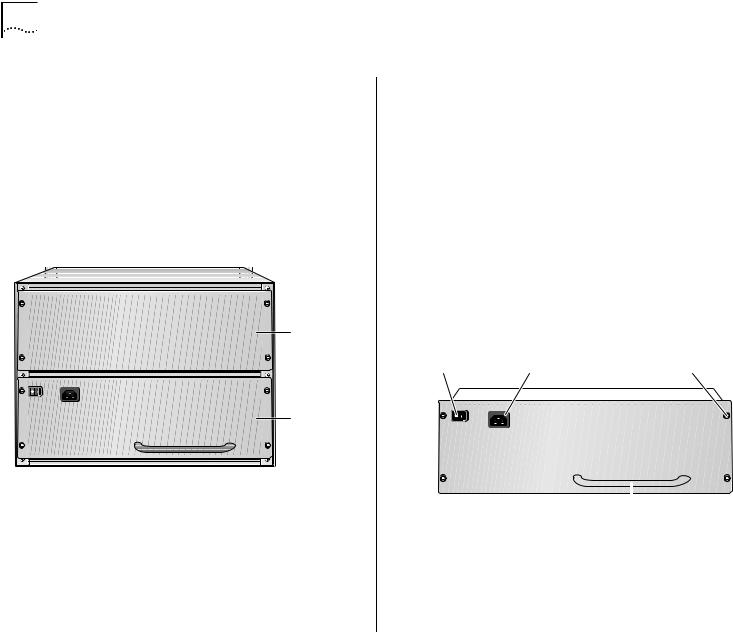
Figure 2 Switch 4007 Chassis Rear View
Power |
supply |
slot 2 |
Power |
supply |
(in slot 1) |
Switch Features
The Switch 4007 has the following features:
■An intelligent power management system.
■An intelligent system inventory management system.
■An integrated, high-performance, distributed network management system.
■Modules and a fan tray that you can install or remove while the switch is operating (called hot swapping), for field upgrades and service.
■Support for 3Com Transcend® Network Control Services for UNIX or for Windows.

■Slots for two Enterprise Management Engine (EME) management modules that do not take up interface module or switch fabric module space.
Switch 4007 starter kits are supplied with with one management module (Model Number: 3CB9EME) installed in the lower slot. You can install a second management module to provide standby management support.
The management module uses the management bus to send commands to all installed interface modules and the switch fabric module and to collect information from the modules.
■A single passive backplane that enables the use of multiple networking technologies, defined by the type of switch fabric module that is installed.
■One slot for a switch fabric module in the chassis to provide optimal network performance.
■Gigabit Ethernet starter kits (Model Numbers 3C16810 and 3C16811) have one 24-port Switching Fabric (Model Number: 3CB9FG24T) preinstalled in slot 7.
■Fast Ethernet starter kits (Model Numbers 3C16815 and 3C16816) have one 9-port Switching Fabric (Model Number: 3CB9FG9) preinstalled in slot 7.
■Slots for two power supplies to supply 930 watts with n + 1 redundancy and 1860 watts without n + 1 redundancy, depending on the type and quantity of installed modules.
Switch 4007 starter kits have one 930W AC Power Supply (Model Number: 3CB9EP9) preinstalled in the lower bay.
Overview 13
■Power supplies that you can add or replace while the chassis is running (referred to as warm swapping).
■Slots for six interface modules. In Switch 4007 starter kits, modules are preinstalled in slots 1 and 2, and the remaining slots are empty.
■Packet switching at an aggregated bandwidth of up to 30 Gbps.
■Power fault-tolerant mode where you can reserve the power of a single power supply (930 watts) to act as a backup if the other power supply fails.
■One exhaust fan tray (with the power and reliability of four fans) to make sure that the chassis maintains the optimal temperature for operation.
Management Features
You can manage the Switch 4007 through:
■An out-of-band terminal interface
■Simple Network Management Protocol (SNMP)
■3Com Transcend Network Supervisor
■3Com Transcend Network Control Services
■A standard Telnet client-to-server application
■Embedded Web-based management
To learn more about management features, see Chapter 5, “Management Tools”.

14 CHAPTER 1: ABOUT THE SWITCH 4007
Switch 4007 Starter Kits
3Com enables you to simplify your installation by selecting from four pre-configured starter kits.
Four configurations are available:
■Layer 2 Gigabit Ethernet Starter Kit Model Number: 3C16810
■Layer 3 Gigabit Ethernet Starter Kit Model Number: 3C16811
■Layer 3 Fast Ethernet (10/100BASE-TX) Starter Kit Model Number: 3C16815
■Layer 3 Fast Ethernet (10/100BASE-TX and 100BASE-FX) Starter Kit
Model Number: 3C16816
Layer 2 Gigabit Ethernet Starter Kit
Model Number: 3C16810
The Layer 2 Gigabit Ethernet Starter Kit has 18 Gigabit Ethernet ports.
This starter kit is preinstalled with the following options:
■EME Management Module (Model Number: 3CB9EME) in the lower slot
■930W AC Power Supply (Model Number: 3CB9EP9)
■One 24-port Switching Fabric (Model Number: 3CB9FG24T) in slot 7
■Two 9-port Gigabit Switching Modules (Model Number: 3CB9LG9MC) in slots 1 and 2
■4 empty slots (slots 3,4,5,6)
You can expand the system to provide 54 Gigabit Ethernet ports by installing additional modules into the empty slots.
Layer 3 Gigabit Ethernet Starter Kit
Model Number: 3C16811
The Layer 3 Gigabit Ethernet Starter Kit has 13 Gigabit Ethernet ports.
This starter kit is preinstalled with the following options:
■EME Management Module (Model Number: 3CB9EME) in the lower slot
■930W AC Power Supply (Model Number: 3CB9EP9)
■One 24-port Switching Fabric (Model Number: 3CB9FG24T) in slot 7
■One 9-port Gigabit Switching Module (Model Number: 3CB9LG9MC) in slot 1
■One 4-port Gigabit MultiLayer Switching Module (Model Number: 3CB9RG4) in slot 2
■4 empty slots (slots 3,4,5,6)
You can expand the system to provide 49 Gigabit Ethernet ports by installing additional modules into the empty slots.

Layer 3 Fast Ethernet (10/100BASE-TX) Starter Kit
Model Number: 3C16815
The Layer 3 FEN (10/100BASE-TX) Starter Kit has 48 copper Fast Ethernet ports and 3 GBIC slots for uplinks.
This starter kit is preinstalled with the following options:
■EME Management Module (Model Number: 3CB9EME) in the lower slot
■930W AC Power Supply (Model Number: 3CB9EP9)
■One 9-port Switching Fabric (Model Number: 3CB9FG9) in slot 7
■One 36-port 10/100BASE-TX Switching Module (Model Number: 3CB9LF36R) in slot 1
■One 12-port 10/100BASE-TX MultiLayer Switching Module (Model Number: 3CB9RF12R) in slot 2
■4 empty slots (slots 3,4,5,6)
You can expand the system to provide 192 Fast Ethernet ports by installing additional modules into the empty slots.
Layer 3 Fast Ethernet (10/100BASE-TX and 100BASE-FX) Starter Kit
Model Number: 3C16816
The Layer 3 FEN (10/100BASE-TX and 100BASE-FX) Starter Kit has 12 copper and 20 fiber Fast Ethernet ports and 3 GBIC slots for uplinks.
Hardware Components |
15 |
This starter kit is preinstalled with the following options:
■EME Management Module (Model Number: 3CB9EME) in the lower slot
■930W AC Power Supply (Model Number: 3CB9EP9)
■One 9-port Switching Fabric (Model Number: 3CB9FG9) in slot 7
■One 20-port 100BASE-FX Switching Module (Model Number: 3CB9LF20MM) in slot 1
■One 12-port 10/100BASE-TX MultiLayer Switching Module (Model Number: 3CB9RF12R) in slot 2
■4 empty slots (slots 3,4,5,6)
You can expand the system to provide 112 Fast Ethernet ports by installing additional modules into the empty slots.
Hardware Components
This section describes the following chassis components:
■Power Supplies
■Fan Tray
■Modules
16 CHAPTER 1: ABOUT THE SWITCH 4007
Power Supplies
The Switch 4007 can contain two back-loading, 930-watt, modular AC power supplies (Model Number 3CB9EP9). The power supplies provide power to the management modules, switch fabric module, interface modules, fans, and backplane.
Figure 3 shows a 930-watt AC power supply in a Switch 4007 chassis.
Figure 3 930-watt AC Power Supply in the Switch 4007
Power supply slot 2
Power |
supply |
(in slot 1) |
You can add or replace power supplies while the chassis is running (referred to as warm swapping). See Chapter 6, “Maintaining the Switch 4007”, for instructions about how to replace a faulty power supply.
930-watt AC Power Supply
Switch 4007 power supplies are autosensing. Each power supply (Figure 3) can automatically sense the type of input voltage to which it is being connected at the electrical outlet.
The power supplies are load sharing in that all power supplies provide an equal amount of the load current. Each 930-watt power supply has its own power cord and is shipped separately from the chassis. The type of power cord depends on your country location.
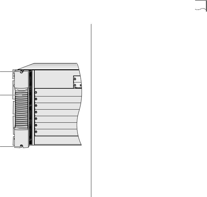
Figure 4 shows the 930-watt AC power supply for the Switch 4007 chassis.
Figure 4 930-watt AC Power Supply for the Switch 4007
Standby/On |
|
AC input |
|
Spring-loaded |
|
|||||
switch |
|
socket |
|
screw |
|
|||||
|
|
|
|
|
|
|
|
|
|
|
|
|
|
|
|
|
|
|
|
|
|
|
|
|
|
|
|
|
|
|
|
|
|
|
|
|
|
|
|
|
|
|
|
|
|
|
|
|
|
|
|
|
|
|
|
|
|
|
|
|
|
|
|
|
|
|
|
|
|
|
|
|
|
|
|
|
|
|
|
|
|
|
|
|
|
|
|
|
|
|
|
|
|
|
|
|
|
|
Power supply handle
Hardware Components |
17 |
Fan Tray |
Module Slots in the Switch 4007 Chassis |
|
The Switch 4007 chassis contains one fan tray, which |
You insert modules horizontally into the chassis. Slots |
|
contains four fans (Model Number 3CBEF7). The fans |
||
are numbered from bottom to top, with the bottom |
||
cool the interface modules, the switch fabric module, |
||
slot being number 1. |
||
and the management modules. |
||
|
Figure 5 Switch 4007 Chassis Fan Tray |
|
The chassis contains: |
|
|
■ Management slots — There are two slots (slot 8 |
||
|
|
|
|
|
|
|
and slot 9) for management modules: |
Spring-loaded |
|
|
■ The Enterprise Management Engine (EME) is an |
screw |
|
|
|
|
|
SNMP-based network management module |
|
|
|
|
|
|
|
9 |
that manages and controls the Switch 4007 and |
|
|
|
|
|
|
8 |
its modules. The management module is the |
Fan tray |
7 |
|
primary communication mechanism into the |
|
|
switch and modules. You manage other |
|
handle |
|
|
|
|
6 |
|
intelligent modules within the chassis through |
|
|
|
|
|
5 |
|
the management module. |
|
4 |
|
■ The Enterprise Management Controller (EMC) |
|
3 |
|
module provides standby controller functions |
|
2 |
|
for an EME in a Switch 4007. |
|
|
|
|
|
1 |
|
■ Payload slots — There are six slots (slot 1 through |
|
|
|
slot 6) for interface modules. The interface |
Spring-loaded |
|
|
modules offer a selection of packet-based or |
|
|
cell-based interfaces that work with the switch |
|
screw |
|
|
fabric module. |
|
|
|
|
|
|
|
■ Switch fabric slots — There is one slot (slot 7) for |
|
|
|
a Gigabit Ethernet Switch Fabric Module, which is |
|
|
|
the central backplane aggregator for the Switch. |
|
|
|
To learn more about management, switch fabric, and |
|
|
|
Fast Ethernet and Gigabit Ethernet interface modules, |
|
|
|
see Chapter 2, “Switch 4007 Modules”. |

18 CHAPTER 1: ABOUT THE SWITCH 4007

SWITCH 4007 MODULES
2
This chapter contains the following topics:
■Overview
■Switch Fabric Modules
■Management Modules
■Fast Ethernet Modules
■Gigabit Ethernet Modules
■GBIC Transceivers
■Slot Restrictions
■Management Access
■Where to Go from Here
Overview
The 3Com® Switch 4007 is a high performance, high-density, aggregation switch. The Switch 4007 has a modular 7-slot chassis that contains slots for the following types of modules:
■Management Modules (see page 21)
The EME management module exchanges information with all modules through the management bus. The EME uses the management bus to send commands to all chassis modules and to collect information from interface modules.
The Switch 4007 is required to have a minimum of one EME (Enterprise Management Engine) management module. You can install a second EME for redundant management operation.
■Switch Fabric Modules (see page 20)
The Gigabit Ethernet (GEN) switch fabric module is the central backplane aggregator for the chassis. Switch fabric modules fit into slot 7 of the
Switch 4007 chassis.
■Fast Ethernet Modules (see page 22) and Gigabit Ethernet Modules (see page 23)
Interface modules pass data through the switch fabric module. The data may get sent back out to other modules or sent out through a switch fabric module front panel port to another device.
The Switch 4007 contains six slots for interface modules. Fast Ethernet or Gigabit Ethernet modules can occupy every slot except slot 7. The six interface modules access five 2 Gbps serial channels, which are wired to one dedicated switch fabric module slot.
20 CHAPTER 2: SWITCH 4007 MODULES
Switch Fabric Modules
The Switch 4007 supports 9-port and 24-port Gigabit Ethernet Switch Fabric modules. Both switch fabric modules fit into slot 7 of the Switch 4007 chassis.
3Com enables you to simplify your installation by selecting from four pre-configured starter kits.
■Fast Ethernet starter kits are pre-configured with one 9-port Switching Fabric (Model Number: 3CB9FG9) in slot 7.
■Gigabit Ethernet starter kits are pre-configured with one 24-port Switching Fabric (Model Number: 3CB9FG24T) in slot 7.
The Switch Fabric modules support the following key features:
■18 Gbps or 48 Gbps switching capacity
■Hot-swapping of modules
■IEEE 802.1D Spanning Tree Protocol bridging for Gigabit Ethernet
■Multicast packet firewall to limit broadcast storms
■Port trunking support for 12 groups, with up to six ports in a group
■IEEE 802.1Q VLAN tagging for up to 126 groups of port-based virtual LANs (VLANs)
■Embedded Simple Network Management Protocol (SNMP) management agent
■Support for four RMON-1 groups: Ethernet Statistics, History, Events, and Alarms
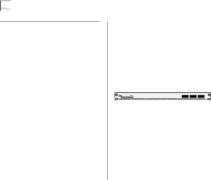
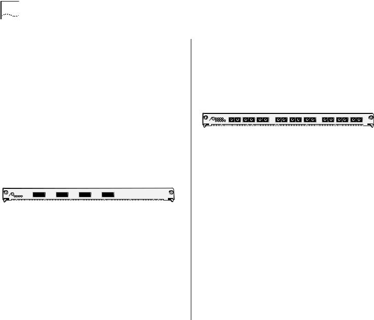
9-port Gigabit Ethernet Switch Fabric
Model Number: 3CB9FG9
The 9-port Gigabit Ethernet (GEN) Switch Fabric Module is optimized for use in wiring closets. The module has six non-blocking Gigabit Ethernet ports that connect directly to the chassis backplane to provide high-speed, low-latency connectivity between Switch 4007 interface modules. Its front panel features three non-blocking Gigabit Interface Converter (GBIC) interface ports that accept optional GBIC transceivers (see “GBIC Transceivers” on
page 25). Figure 6 shows the front panel.
Figure 6 Front Panel of 9-port Switch Fabric Module
|
|
|
AT |
|
|
|
C |
|
|
|
|
|
|
|
|
O |
N |
T |
N E |
L |
R |
X |
7 |
T |
X |
R |
X |
8 |
T |
X |
R |
X |
9 |
T |
X |
3CB9FG9 |
|
|
|
P R |
|
E |
|
|
|
|
|
|
|
R |
A |
|
|
|
|
|
|
|
|||||||||||||||
|
|
S T |
|
|
S |
|
|
|
|
|
|
|
|
F |
|
|
P |
|
|
|
|
|
|
|
|
|
|
|
|
|
|
|
|
|
|
|
M |
O |
D |
|
|
|
|
|
1 |
2 |
3 |
4 |
5 |
6 |
7 |
|
|
|
8 |
|
|
9 |
|
|
|
|
|
|
|
|
|
|
|
|
|
|
|
|
|
|
|
I |
|
|
|
|
|
|
|
|
|
|
|
|
|
|
|
|
|
|
|
|
|
|
|
|
|
|
|
|
|
|
|
To learn more about this module, refer to the 9-Port Gigabit Ethernet Switch Fabric Module Quick Start Guide on the Online Manuals CD-ROM.
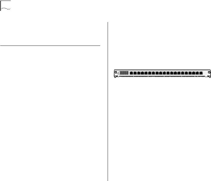
24-port Gigabit Ethernet Switch Fabric
Model Number: 3CB9FG24T
The 24-port Gigabit Ethernet (GEN) Switch Fabric Module is designed for use in network backbones, data centers, and other high-density network segments. The 24-port GEN Switch Fabric Module has 24 nonblocking Gigabit Ethernet ports that connect to the chassis backplane to provide high-speed, low-latency connectivity between Switch 4007 switching modules. Figure 7 shows the front panel.
Figure 7 Front Panel of 24-port Switch Fabric Module
|
|
|
|
|
I |
|
|
|
|
|
|
|
|
|
|
|
|
|
|
|
|
|
|
|
|
3CB9FG24T |
|
|
AT |
S |
E |
C |
2 |
4 |
6 |
8 |
1 |
0 |
1 |
2 |
1 |
4 |
1 |
6 |
1 |
8 |
2 |
0 |
2 |
2 |
2 |
4 |
|
|
S T |
|
|
|
|
|
|
|
|
|
|
|
|
|
|
|
|
|
|
|
|
|
|
|
|
|
M |
O D |
|
|
|
|
|
|
|
|
|
|
|
|
|
|
|
|
|
|
|
|
|
|
|
|
|
|
|
|
P |
R |
|
1 |
3 |
5 |
7 |
9 |
|
1 |
1 |
1 |
3 |
1 |
5 |
1 |
7 |
1 |
9 |
2 |
1 |
2 |
3 |
|
To learn more about this module, refer to the 24-Port Gigabit Ethernet Switch Fabric Module Quick Start Guide on the Online Manuals CD-ROM.
Management Modules
The Switch 4007 chassis contains two slots (slots 8 and 9) for Management Modules
management modules. These modules do not occupy module payload slots. Figure 8 shows the front panel.
Management Modules |
21 |
You manage the switch through:
■The EME command interface, which you access through the serial port, or through SNMP (Simple Network Management Protocol).
■The Switch 4007 Web Management suite of applications.
■3Com Transcend Network Control Services.
An EME combines the functions of a management module and a controller module. You can install a second EME to provide standby management support if the first EME is unavailable for any reason.
Table 3 describes the EME access mechanisms.
Figure 8 Front Panel of EME Management Module
|
|
|
IVE |
|
|
|
LY |
|
|
|
|
ET |
|
|
SE |
T |
IS |
|
|
|
|
|
|
|
|||
|
|
T |
|
|
|
|
M |
E |
S |
|
E |
|
SS |
|
|
|
|
|
|
|
|
||||||
A |
C |
|
|
Y |
|
|
S |
P |
E |
E |
|
R |
H |
A |
|
|
|
|
|
|
|
|
|
||||
ST |
B |
|
D |
|
R |
|
|
C |
|
|
|
|
|
|
|
|
|
|
|||||||||
|
|
|
|
-T |
|
|
|
|
|
|
|
|
|
|
|
|
|
|
|
2 |
|
T |
|
|
|
||
|
|
|
|
|
|
|
|
|
|
|
|
|
|
|
|
|
|
|
|
3 |
|
|
|
X |
|||
|
|
|
|
|
|
B |
|
|
|
|
|
|
|
|
|
|
|
|
|
|
2 |
|
- |
|
U |
||
|
|
|
|
|
0 |
|
|
|
|
|
|
|
|
|
|
|
|
|
R |
S |
|
0B |
|
A |
|
||
|
|
|
|
|
1 |
|
|
|
|
|
|
|
|
|
|
|
|
|
|
|
|
1 |
|
|
|
||
3CB9EME
Table 3 EME Access Mechanisms
.
Access |
Allows you to |
Using |
Mechanism |
|
|
|
|
|
Terminal |
Connect directly to the |
RS-232 serial |
|
command interface. |
port |
You can communicate through an RS-232 connector (for connection to a terminal) or an RJ-45 port (for connection to Ethernet networks) on the front panel of the EME to configure and report on switch and module operation.
The Switch 4007 EME is an SNMP-based network management module that allows you to configure and manage the Switch 4007 chassis and modules. The EME backplane services generate, control, and monitor the Switch. The management modules provide power management functions.
Modem |
Access the command |
Auxiliary RS-232 |
|
interface from remote |
serial port |
|
sites. |
|
IP |
Access the command |
10BASE-T |
|
interface using the |
Ethernet port |
|
rlogin or telnet |
assigned to an IP |
|
commands, or use an |
interface |
|
external SNMP |
|
|
management |
|
|
application to |
|
|
communicate with the |
|
|
embedded SNMP agent. |
|
|
|
|
22 CHAPTER 2: SWITCH 4007 MODULES
For information about how to install the EME and how to perform an initial configuration, see the
Enterprise Management Engine Quick Start Guide on the Online Manuals CD-ROM.
Fast Ethernet Modules
The frame-based switching modules are intelligent Layer 2 and Layer 3 modules that have their own embedded agent. These modules are physically connected to the backplane ports of the switch fabric module in the chassis. These modules switch between the front panel ports and the backplane ports. Switching interface modules provide network connectivity functions.
Fast Ethernet Interface Modules are available in these port configurations:
■20-port 100BASE-FX (MT-RJ) Fast Ethernet Layer 2 Switching Module
■36-port 10/100BASE-TX Fast Ethernet RJ-45 Layer 2 Switching Module
■12-port 10/100BASE-TX Fast Ethernet MultiLayer Switching Module
20-port 100BASE-FX (MT-RJ) Fast Ethernet Layer 2 Switching Module
Model Number: 3CB9LF20MM
The 100BASE-FX (MT-RJ) Fast Ethernet Layer 2 Switching Module has twenty 100 Mbps Ethernet fiber-optic ports with MT-RJ connectors on its front panel and two 1-Gigabit ports for connection to the
chassis backplane. It operates as a Layer 2 switch and occupies a single interface module slot in the
Switch 4007 chassis.
Figure 9 identifies the components on the front panel of the module. The front panel ports on the module are numbered 1 through 20. The two 1-Gigabit ports on the back of the module are numbered 21 and 22.
Figure 9 Front Panel of Module 3CB9LF20MM
|
|
|
|
AT |
1 |
4 |
2 |
3 |
4 |
5 |
6 |
1 |
X |
1 |
2 |
X |
2 |
3 |
X |
3 |
4 |
X |
4 |
5 |
X |
6 |
X6 |
7 |
X |
7 |
8 |
X |
8 |
9 |
9 |
X |
1 |
01 |
0 |
X |
1 |
1 |
X |
1 |
2 |
X |
1 |
3 |
1 |
3 |
X |
1 |
4 |
1 |
4 |
X |
1 |
5 |
1 |
5 |
X |
1 |
61 |
6 |
X |
1 |
7 |
1 |
7 |
X |
1 |
8 |
1 |
8 |
X |
1 |
9 |
1 |
9 |
X |
2 |
0 |
2 |
0 |
X |
3CB9LF20MM3CB9LF20R |
|
|
|
S T |
|
|
|
|
|
|
|
|
|
|
|
|
|
|
|
|
|
|
|
|
|
|
|
|
|
|
|
|
|
|
|
|
|
|
|
|
|
|
|
|
|
|
|
|
|
|
|
|
|
|
|
|
|
|
|
|
|
|
|
|
|
|
|
|
|
|
|
|
|
|
|
|
|
|
|
|
|
|
|
|
|
|
|
|
|
D |
|
|
|
|
|
|
|
|
|
|
|
|
|
|
|
|
|
|
|
|
|
|
|
|
|
|
|
|
|
|
|
|
|
|
|
|
|
|
|
|
|
|
|
|
|
|
|
|
|
|
|
|
|
|
|
|
|
|
|
|
|
|
|
|
|
|
|
|
|
|
|
|
|
|
|
|
|
|
|
|
|
|
|
|
M |
O |
|
|
7 |
|
|
|
|
|
|
|
|
|
|
|
|
|
|
|
|
|
|
|
|
|
|
|
|
|
|
|
|
|
|
|
|
|
|
|
|
|
|
|
|
|
|
|
|
|
|
|
|
|
|
|
|
|
|
|
|
|
|
|
|
|
|
|
|
|
|
|
|
|
|
|
|
|
|
|
|
|
|
|
|
|
|
|
|
|
|
|
|
|
|
|
|
|
|
|
|
|
|
|
|
|
|
|
|
|
|
|
|
|
|
|
|
|
|
|
|
|
|
|
|
|
|
|
|
|
|
|
|
|
|
|
|
|
|
|
|
|
|
|
|
|
|
|
|
|
|
|
|
|
|
|
|
|
|
|
|
|
|
|
|
|
|
|
|
|
|
|
To learn more about this module, refer to the 20-Port 100BASE-FX (MT-RJ) Fast Ethernet Layer 2 Switching Module Quick Start Guide on the Online Manuals CD-ROM.
36-port 10/100BASE-TX Fast Ethernet RJ-45 Layer 2 Switching Module
Model Number: 3CB9LF36R
The 10/100BASE-TX Fast Ethernet RJ-45 Layer 2 Switching Module (36-port FEN RJ-45 Switching Module) has thirty-six 10/100 Mbps Ethernet ports with RJ-45 connectors on its front panel, and two 1-Gigabit ports on the back for connection to the chassis backplane. It operates as a Layer 2 switch and occupies a single interface module slot in the
Switch 4007 chassis.
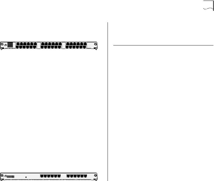
Figure 10 identifies the components on the front panel of the module.
Figure 10 Front Panel of Module 3CB9LF36R
|
|
AT |
3 |
1 |
3 |
6 |
X |
1 |
3 |
X |
2 |
5 |
X |
3CB9LF36R |
|
|
|
1 |
6 |
1 |
|||||||||
|
S T |
|
|
|
|
7 |
|
1 |
9 |
|
3 |
1 |
|
|
M |
O D |
|
|
|
|
|
|
|
|
|
|
|
|
|
|
|
|
|
|
|
|
|
|
X |
|
|
X |
|
|
|
|
|
|
|
|
|
X |
|
|
|
|
|
To learn more about this module, refer to the 36-Port 10/100BASE-TX Fast Ethernet RJ-45 Layer 2 Switching Module Quick Start Guide on the Online Manuals CD-ROM.
12-port 10/100BASE-TX Fast Ethernet MultiLayer Switching Module
Model Number: 3CB9RF12R
The 12-port 10/100BASE-TX Fast Ethernet MultiLayer Switching Module is a multiprotocol module designed for the Switch 4007. The module has twelve 10/100BASE-TX Fast Ethernet front panel ports that provide a 100 Mbps connection over UTP-Category 5 cables, and one nonblocking Gigabit Ethernet port that connects through the backplane to the switch fabric module. The module has two groups of six ports, operates as a Layer 3 router switch, and occupies a single interface module slot in the
Switch 4007 chassis.
Figure 11 identifies the components on the front panel of the module.
Figure 11 Front Panel of Module 3CB9RF12R
|
|
AT |
1 |
2 |
3 |
4 |
0 |
5 |
1 |
6 |
2 |
|
|
|
|
|
|
|
|
1 |
|
1 |
|
1 |
|
3CB9RF12R |
|
S T |
|
7 |
8 |
9 |
1 |
|
1 |
|
1 |
|
|
|
|
|
|
|
|
|
|
|
|
|
|
|
|
M |
O D |
|
|
|
|
|
|
|
|
|
|
|
|
|
|
|
|
|
|
|
|
|
|
|
|
|
|
|
|
|
|
|
|
|
|
|
|
|
|
|
|
|
|
|
|
|
|
|
|
|
|
|
|
|
|
|
|
|
|
|
|
|
|
|
1 |
2 |
3 |
4 |
5 |
6 |
7 |
8 |
9 |
|
0 |
|
1 |
|
2 |
|
Gigabit Ethernet Modules |
23 |
To learn more about this module, refer to the 12-Port 10/100BASE-TX Fast Ethernet Layer 3 Switching Module Quick Start Guide on the Online Manuals CD-ROM.
Gigabit Ethernet Modules
The Gigabit Ethernet (GEN) Interface Modules are two-port interface modules for the 3Com
Switch 4007. The GEN interface modules serve as a 2–Gigabit data channel between the Gigabit Ethernet Switch Fabric Module and other 802.3z–compliant Gigabit Ethernet devices. GEN Interface Modules use SC connectors.
Because Gigabit Ethernet interface modules are not intelligent, you cannot access them directly; all communication takes place through the switch fabric module. GEN interface modules serve as a two-Gigabit data channel between the GEN Switch Fabric Module and other 802.3z-compliant Ethernet devices.
For information about how to install these modules, see the module’s Quick Start Guide that is shipped with each module.
Gigabit Ethernet Interface Modules are available in these port configurations:
■4-port Gigabit Ethernet Interface Module
■9-port 1000BASE-SX Gigabit Ethernet Layer 2 Switching Module
■4-port Gigabit MultiLayer Switching Module
24 CHAPTER 2: SWITCH 4007 MODULES
4-port Gigabit Ethernet Interface Module
Model Number: 3CB9LG4
The 4-port Gigabit Ethernet (GEN) Interface Module (GBIC) is an interface for gigabit rate data between the Switch 4007 chassis backplane and other 802.3z-compliant Gigabit Ethernet devices. The module provides four Gigabit Ethernet fiber-optic connections on the front panel, using plug-in Gigabit Interface Converter (GBIC) transceivers. The module occupies a single interface module slot in the
Switch 4007 chassis.
Each module has four ports on the front panel. Figure 12 identifies the components on the front panel of the module.
Figure 12 Front Panel of Module 3CB9LG4
|
|
AT |
R |
X |
T |
X |
R |
X |
T |
X |
R |
X |
T |
X |
R |
X |
T |
X |
3CB9LG4 |
|
S T |
|
|
|
|
|
|
|
|
|
|
|
|
|
|
|
|
||
|
|
|
|
|
|
|
|
|
|
|
|
|
|
|
|
|
|
|
|
M |
O D |
|
|
|
|
|
|
|
|
|
|
|
|
|
|
|
|
|
|
|
|
|
|
|
|
|
|
|
|
|
|
|
|
|
|
|
|
|
1 |
2 |
3 |
4 |
1 |
2 |
3 |
4 |
To learn more about this module, refer to the 4-Port Gigabit Ethernet Interface Module (GBIC) Quick Start Guide on the Online Manuals CD-ROM.
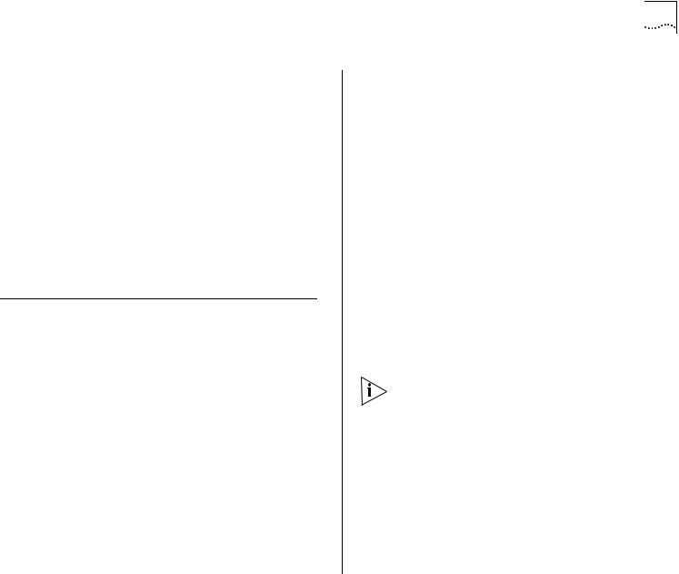
9-port 1000BASE-SX Gigabit Ethernet Layer 2 Switching Module
Model Number: 3CB9LG9MC
The 9-port 1000BASE-SX Gigabit Ethernet Layer 2 Switching Module can switch Gigabit Ethernet (GEN) connections to corporate backbones and servers. The module has nine 1000BASE-SX GEN front panel ports. It has 3 backplane ports for connection to the
24-port GEN Switch Fabric Module, and 1 backplane port for connection to the 9-port GEN Switch Fabric Module. The module occupies a single interface module slot in the Switch 4007 chassis.
Figure 13 identifies the components on the front panel of the module.
Figure 13 Front Panel of Module 3CB9LG9MC
|
|
|
AT |
1 |
2 |
3 |
4 |
5 |
X |
1 |
X |
T |
X |
2 |
X |
T |
X |
3 |
X |
T |
X |
4 |
X |
T |
X |
5 |
X |
T |
X |
6 |
X |
T |
X |
7 |
X |
T |
X |
8 |
X |
T |
X |
R |
X |
3CB9LG9MC |
|
|
|
|
|
|
|
|
|
|
|
|
|
|
|
|
|
|
|
9 |
|
||||||||||||||||||||||||
|
OD |
ST |
|
6 |
7 |
8 |
9 |
|
|
|
|
|
|
|
|
|
|
|
|
|
|
|
|
|
|
|
|
|
|
|
|
|
|
|
|
|
|
|
|
|
|
|
|
|
M |
|
|
|
|
|
|
|
|
|
|
|
|
|
|
|
|
|
|
|
|
|
|
|
|
|
|
|
|
|
|
|
|
|
|
|
|
|
|
|
|
|
|
|
|
To learn more about this module, refer to the 9-Port 1000BASE-SX Gigabit Ethernet Layer 2 Switching Module Quick Start Guide on the Online Manuals CD-ROM.
4-port Gigabit MultiLayer Switching Module
Model Number: 3CB9RG4
The 4-port Gigabit Ethernet Layer 3 Switching Module (GBIC) for the Switch 4007 provides high-port-density, line speed, Gigabit Ethernet switching and routing on backbone networks running at Open Systems Interconnection (OSI) Layer 3.
The module provides 4 Gigabit Interface Converter (GBIC) ports on the front panel that can be either 1000BASE-LX (single-mode fiber) or 1000BASE-SX (multimode fiber). 4 Gigabit Ethernet ports connect the module to the chassis backplane.
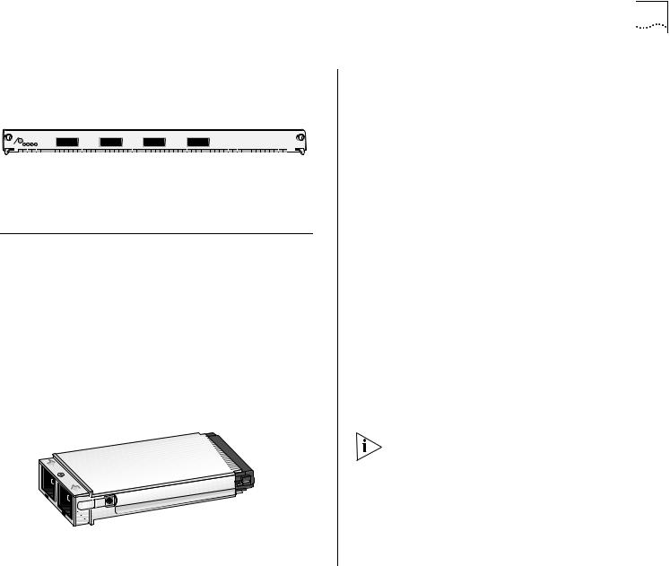
Figure 14 identifies the components on the front panel of the module.
Figure 14 Front Panel of Module 3CB9RG4
|
|
S T |
AT |
3CB9RG4 |
|
O D |
|
|
|
M |
|
|
|
1 |
2 |
3 |
4 |
1 |
2 |
3 |
4 |
To learn more about this module, refer to the 4-Port Gigabit Ethernet Layer 3 Switching Module (GBIC) Quick Start Guide on the Online Manuals CD-ROM.
GBIC Transceivers
The Gigabit Interface Converter (GBIC) ports on your system connect to Gigabit Ethernet networks through a GBIC transceiver (Figure 1), providing a high-speed connection over fiber-optic cable. The transceiver connects to the network using a fiber-optic duplex subscriber connector (SC). You can remove and replace the transceiver with the system powered on, which is called hot-swapping.
Figure 15 GBIC Fiber-Optic Transceiver
GBIC Transceivers |
25 |
The following transceivers are available:
■SX GBIC Transceiver
■LX GBIC Transceiver
■70-km Long Haul GBIC Transceiver
SX GBIC Transceiver
Model Number: 3CGBIC91
The 1000BASE-SX GBIC transceiver supports a direct connection to 62.5-micron or 50-micron multimode fiber-optic cable.
To learn more about this transceiver, refer to the GBIC Transceiver Installation Guide on the Online Manuals CD-ROM.
LX GBIC Transceiver
Model Number: 3CBGIC92
The 1000BASE-LX GBIC transceiver supports a direct connection to single-mode fiber-optic cable, or connection to multimode fiber through a conditioned launch cable.
To ensure optimal performance, compatibility, and regulatory compliance, use only conditioned launch cables that 3Com supports. For a list of supported conditioned launch cables, see this 3Com Web site:
http://www.3Com.com/gigabit_ethernet/gbics
To learn more about this transceiver, refer to the GBIC Transceiver Installation Guide on the Online Manuals CD-ROM.

26 CHAPTER 2: SWITCH 4007 MODULES
70-km Long Haul GBIC Transceiver
Model Number: 3CGBIC97
The 70-km Gigabit Ethernet GBIC Fiber-Optic Transceiver connects to the network using a fiber-optic duplex SC connector.
To learn more about this transceiver, refer to the
70-km Gigabit Ethernet GBIC Transceiver Installation Guide on the Online Manuals CD-ROM.
Slot Restrictions
Table 4 lists slot restrictions in the Switch 4007 chassis.
Table 4 Slot Restrictions
Module type |
Slot number |
|
|
Management modules |
8 and 9 |
|
|
Switch fabric module |
7 |
|
|
Interface modules |
1, 2, 3, 4, 5, 6 |
|
|
Management Access
You can access and manage your Switch 4007 modules using several methods:
■Administration Console
■Web Management suite of applications
■External SNMP-based network management application, such as Transcend® Network Control Services
The Administration Console and most of Web Management are embedded parts of the software and are available for immediate use to manage your modules.
Administration Console Access
To manage the module from the Administration Console:
1Log in to the EME.
For information about logging in to the EME, see the
Enterprise Management Engine User Guide.
2At the prompt, enter:
connect <slot>.1
Where <slot> is the chassis slot number of the module that you want to manage, and the number after the decimal point is a subslot number (which is always 1).
The Administration Console displays the top-level menu prompt. For example, if you installed a 20-port 100BASE-FX Fast Ethernet Switching Module in slot 4, then the prompt appears as follows:
CB9000@4.1 [20-E/FEN-FX-L2] ():
3 Enter commands to manage the module.
For example, to display a module baseline, enter:
module baseline display
For more information about Administration Console module commands, see the multiplatform Command Reference Guide.
Web Management Access
Web Management applications are an embedded part of the Switch 4007. They include Web Console, DeviceView, and Performance monitoring tools. Additional installable applications include online Help.
After you have set up your IP address for the Switch, you can access the Web Management applications directly in your Web browser by entering the IP address. For information about setting up your IP address, see the Enterprise Management Engine Quick Start Guide.
For additional information about Web Management, see Chapter 5, “Management Tools”.
Where to Go from Here
For more information about Switch 4007 see the following documents, which are supplied in PDF format on the Online Manuals CD-ROM:
■Management modules
■Enterprise Management Engine Quick Start Guide
■Switch 4007 Implementation Guide
■Switch 4007 Command Reference Guide
■Interface modules
■20-Port 100BASE-FX (MT-RJ) Fast Ethernet Layer 2 Switching Module Quick Start Guide
■36-Port 10/100BASE-TX Fast Ethernet RJ-45 Layer 2 Switching Module Quick Start Guide
Where to Go from Here |
27 |
■12-Port 10/100BASE-TX Fast Ethernet Layer 3 Switching Module Quick Start Guide
■4-Port Gigabit Ethernet Interface Module (GBIC) Quick Start Guide
■9-Port 1000BASE-SX Gigabit Ethernet Layer 2 Switching Module Quick Start Guide
■4-Port Gigabit Ethernet Layer 3 Switching Module (GBIC) Quick Start Guide
■Switch fabric modules
■24-Port Gigabit Ethernet Switch Fabric Module Quick Start Guide
■9-port Gigabit Ethernet Switch Fabric Module Quick Start Guide
■GBIC transceivers
■GBIC Transceiver Installation Guide
■70-km Gigabit Ethernet GBIC Transceiver Installation Guide
The Switch 4007 is based on 3Com
CoreBuilder® 9000 technology and supports a range of CoreBuilder 9000 components.
The Quick Start Guides that are supplied with many product options describe installation and setup procedures for the CoreBuilder 9000. However, you can install supported components into a Switch 4007 chassis as you would install them into the CoreBuilder 9000 7-slot chassis.

28 CHAPTER 2: SWITCH 4007 MODULES
 Loading...