


 Loading...
MARINE RADAR


 FR-8062, FR-8122, FR-8252

SAFETY INSTRUCTIONS

 SAFETY INSTRUCTIONS
 WARNING
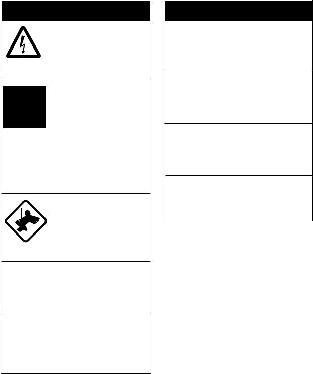
Radio Frequency Radiation Hazard
The radar antenna emits electromagnetic radio frequency (RF) energy which can be harmful, particularly to your eyes. Never look directly into the antenna aperture from a close distance while the radar is in operation or expose yourself to the transmitting antenna at a close distance.
Distances at which RF radiation levels of 100 W/m2 and 10 W/m2 exist are given in the table below.
Note: If the antenna unit is installed at a close distance in front of the wheel house, it may be necessary to prevent transmission in that area to protect passengers and crew from microwave radiation. This can be done with Sector Blank in the System menu.
Model |
Antenna |
Distance to |
Distance to |
||
100 W/m2 point |
10 W/m2 point |
||||
FR-8062 |
|
XN-12A |
Nil |
1.20 m |
|
|
XN-13A |
Nil |
1.10 m |
||
|
|
||||
FR-8122 |
XN-12A |
Nil |
1.90 m |
||
XN-13A |
Nil |
1.40 m |
|||
|
|
||||
FR-8252 |
XN-12A |
0.40 m |
4.60 m |
||
XN-13A |
0.40 m |
3.10 m |
|||
|
|
||||
i
SAFETY INSTRUCTIONS
 WARNING
ELECTRICAL SHOCK HAZARD
Do not open the equipment.
Only qualified personnel should work inside the equipment.
Turn off the radar power switch before servicing the antenna unit. Post a warning sign near the switch indicating it should not be turned on while the antenna unit is being serviced.
Prevent the potential risk of being struck by the rotating antenna and exposure to RF radiation hazard.
Wear a safety belt and hard hat when working on the antenna unit.
Serious injury or death can result if someone falls from the radar antenna mast.
Do not disassemble or modify the equipment.
Fire, electrical shock or serious injury can result.
Turn off the power immediately if water leaks into the equipment or the equipment is emitting smoke or fire.
Continued use of the equipment can cause fire or electrical shock.
 WARNING
Use the proper fuse.
Fuse rating is shown on the equipment. Use of a wrong fuse can result in damage to the equipment.
Keep heater away from equipment.
Heat can alter equipment shape and melt the power cord, which can cause fire or electrical shock.
Do not place liquid-filled containers on the top of the equipment.
Fire or electrical shock can result if a liquid spills into the equipment.
Do not operate the equipment with wet hands.
Electrical shock can result.
ii

 WARNING
No one navigational aid should be relied upon for the safety of vessel and crew. The navigator has the responsibility to check all aids available to confirm position. Electronic aids are not
a substitute for basic navigational principles and common sense.
•The ARP automatically tracks automatically or manually acquired radar targets and calculates their courses and speeds, indicating them by vectors. Since the data generated by the auto plotter are based on what radar targets are selected, the radar must always be optimally tuned for use with the ARP to ensure required targets will not be lost or unwanted targets such as sea returns and noise will not be acquired and tracked.
•A target does not always mean a landmass, reef, ships or other surface vessels but can imply returns from sea surface and clutter. As the level of clutter changes with environment, the operator should properly adjust the A/C SEA, A/C RAIN and GAIN controls to be sure target echoes are not eliminated from the
radar screen.
SAFETY INSTRUCTIONS
 CAUTION
The plotting accuracy and response of this ARP meets IMO standards. Tracking accuracy is affected by the following:
•Tracking accuracy is affected by course change. One to two minutes is required to restore vectors to full accuracy after an abrupt course change. (The actual amount depends on gyrocompass specifications.)
•The amount of tracking delay is inversely proportional to the relative speed of the target. Delay is on the order of 15-30 seconds for high relative speed; 30-60 seconds for low relative speed.
The data generated by ARP and AIS are intended for reference purposes only.
Check all available navigation aids to determine target moviement.
iii
SAFETY INSTRUCTIONS
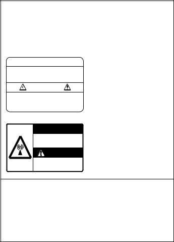
WARNING LABELS
Warning labels are attached to the equipment. Do not remove any label. If a label is missing or damaged, contact a FURUNO agent or dealer about replacement.
 WARNING
To avoid electrical shock, do not remove cover. No user-serviceable parts inside.

 WARNING
Radiation hazard. Only qualified personnel should work inside scanner. Confirm that TX has stopped before opening scanner.
DISPLAY UNIT
Name: Warning Label 1
Type: 86-003-1011-1
Code No.: 100-236-231
ANTENNA UNIT
Name: Warning Sticker
Type: 03-142-3201-0
Code No.: 100-266-890
TFT LCD
The high quality TFT (Thin Film Transistor) LCD displays 99.999% of its picture elements.
The remaining 0.001% may drop out or light, however this is an inherent property of the LCD; it is not a sign of malfunction.
iv
TABLE OF CONTENTS
|
|
|
|
...............................................................................................FOREWORD |
ix |
||
SYSTEM CONFIGURATION ...................................................................... |
xi |
||
1. |
OPERATIONAL OVERVIEW.............................................................. |
1-1 |
|
|
1.1 |
Controls ..................................................................................................................... |
1-1 |
|
1.2 |
Turning the Radar On/Off, Transmitting .................................................................... |
1-3 |
|
1.3 |
Display Indications..................................................................................................... |
1-4 |
|
1.4 |
Adjusting Display Brilliance, Panel Dimmer............................................................... |
1-5 |
|
1.5 |
Menu Overview.......................................................................................................... |
1-5 |
|
1.6 |
Tuning........................................................................................................................ |
1-7 |
|
1.7 |
Presentation Modes................................................................................................... |
1-8 |
|
1.8 |
Choosing a Range Scale......................................................................................... |
1-10 |
|
1.9 |
Choosing a Pulse Length ........................................................................................ |
1-11 |
|
1.10 |
Adjusting the Gain (sensitivity) ................................................................................ |
1-12 |
|
1.11 |
Suppressing Sea Clutter.......................................................................................... |
1-13 |
|
1.12 |
Suppressing Rain Clutter......................................................................................... |
1-14 |
|
1.13 |
Automatic Suppression of Sea and Rain Clutters ................................................... |
1-15 |
|
1.14 |
Cursor...................................................................................................................... |
1-16 |
|
1.15 |
Interference Rejector ............................................................................................... |
1-17 |
|
1.16 |
Measuring the Range to a Target............................................................................ |
1-18 |
|
1.17 |
Measuring the Bearing to a Target .......................................................................... |
1-20 |
|
1.18 |
Measuring the Range and Bearing Between Two Targets...................................... |
1-21 |
|
1.19 |
Target Alarm............................................................................................................ |
1-22 |
|
1.20 |
Off Centering the Display ........................................................................................ |
1-24 |
|
1.21 |
Zoom ....................................................................................................................... |
1-25 |
|
1.22 |
Echo Stretch ............................................................................................................ |
1-27 |
|
1.23 |
Echo Averaging ....................................................................................................... |
1-28 |
|
1.24 |
Target Trails ............................................................................................................ |
1-29 |
|
1.25 |
Parallel Index Lines ................................................................................................. |
1-34 |
|
1.26 |
Outputting Target Position, Inscribing Origin Mark.................................................. |
1-35 |
|
1.27 |
Temporarily Hiding the Heading Line ...................................................................... |
1-36 |
|
1.28 |
Custom Setup.......................................................................................................... |
1-36 |
|
1.29 |
Programming Function Keys (F1 and F2 keys) ....................................................... |
1-39 |
|
1.30 |
Noise Rejector ......................................................................................................... |
1-40 |
|
1.31 |
Suppressing Second-trace Echoes ......................................................................... |
1-40 |
|
1.32 |
Watchman ............................................................................................................... |
1-41 |
|
1.33 |
Color Schemes ........................................................................................................ |
1-42 |
|
1.34 |
Navigation Data ....................................................................................................... |
1-43 |
|
1.35 |
Dynamic Range ....................................................................................................... |
1-45 |
|
1.36 |
Characteristics Curve .............................................................................................. |
1-45 |
|
1.37 |
Antenna Speed........................................................................................................ |
1-46 |
|
1.38 |
Waypoint Marker ..................................................................................................... |
1-46 |
|
1.39 |
Alarm Message Display........................................................................................... |
1-47 |
|
1.40 |
Echo Area................................................................................................................ |
1-49 |
|
1.41 |
Customizing (Initial Menu) ....................................................................................... |
1-50 |
|
1.42 |
Sector Blank ............................................................................................................ |
1-52 |
|
1.43 |
GPS Buoy................................................................................................................ |
1-54 |
2. |
RADAR OBSERVATION .................................................................... |
2-1 |
|
|
2.1 |
General...................................................................................................................... |
2-1 |
|
2.2 |
False Echoes............................................................................................................. |
2-3 |
|
2.3 |
SART (Search and Rescue Transponder)................................................................. |
2-5 |
v
TABLE OF CONTENTS |
|
||
|
2.4 |
RACON ..................................................................................................................... |
2-6 |
3. |
ARP OPERATION .............................................................................. |
3-1 |
|
|
3.1 |
Usage Precautions.................................................................................................... |
3-1 |
|
3.2 |
Controls for Use with ARP ........................................................................................ |
3-2 |
|
3.3 |
ARP Display On/Off .................................................................................................. |
3-2 |
|
3.4 |
Acquiring and Tracking Targets ................................................................................ |
3-3 |
|
3.5 |
Terminating Tracking of ARP Targets....................................................................... |
3-4 |
|
3.6 |
Vector Attributes........................................................................................................ |
3-5 |
|
3.7 |
History Display (target past position) ........................................................................ |
3-6 |
|
3.8 |
ARP Target Data....................................................................................................... |
3-7 |
|
3.9 |
CPA/TCPA Alarm...................................................................................................... |
3-8 |
|
3.10 |
Proximity Alarm ......................................................................................................... |
3-9 |
|
3.11 |
Lost Target ................................................................................................................ |
3-9 |
|
3.12 |
Symbol Color........................................................................................................... |
3-10 |
4. |
AIS OPERATION................................................................................ |
4-1 |
|
|
4.1 |
Controls for Use with AIS ......................................................................................... |
4-1 |
|
4.2 |
Turning the AIS Display On or Off............................................................................. |
4-1 |
|
4.3 |
AIS Symbols.............................................................................................................. |
4-2 |
|
4.4 |
Activating, Sleeping Targets ..................................................................................... |
4-2 |
|
4.5 |
Displaying AIS Target Data....................................................................................... |
4-3 |
|
4.6 |
Display Range........................................................................................................... |
4-4 |
|
4.7 |
Sorting Targets.......................................................................................................... |
4-4 |
|
4.8 |
Displaying Targets Within a Specific Sector ............................................................. |
4-5 |
|
4.9 |
Number of Targets to Display ................................................................................... |
4-5 |
|
4.10 |
Vector Attributes........................................................................................................ |
4-6 |
|
4.11 |
History Display (target past position) ........................................................................ |
4-7 |
|
4.12 |
CPA/TCPA Alarm...................................................................................................... |
4-8 |
|
4.13 |
Proximity Alarm ......................................................................................................... |
4-9 |
|
4.14 |
Lost Target ................................................................................................................ |
4-9 |
|
4.15 |
Symbol Color........................................................................................................... |
4-10 |
5. |
GPS OPERATION .............................................................................. |
5-1 |
|
|
5.1 |
Navigator Type.......................................................................................................... |
5-1 |
|
5.2 |
Datum........................................................................................................................ |
5-2 |
|
5.3 |
WAAS Setup ............................................................................................................. |
5-2 |
|
5.4 |
Satellite Monitor ........................................................................................................ |
5-3 |
|
5.5 |
Displaying Type 16 Message .................................................................................... |
5-4 |
|
5.6 |
GPS Sensor Installation Position Offset.................................................................... |
5-5 |
|
5.7 |
Cold Start .................................................................................................................. |
5-6 |
6. |
MAINTENANCE & TROUBLESHOOTING ........................................ |
6-1 |
|
|
6.1 |
Preventive Maintenance............................................................................................ |
6-2 |
|
6.2 |
Fuse Replacement .................................................................................................... |
6-3 |
|
6.3 |
Magnetron Life .......................................................................................................... |
6-3 |
|
6.4 |
LCD Backlight Life..................................................................................................... |
6-3 |
|
6.5 |
Trackball Maintenance .............................................................................................. |
6-4 |
|
6.6 |
Simple Troubleshooting ............................................................................................ |
6-5 |
|
6.7 |
Advanced-level Troubleshooting............................................................................... |
6-6 |
|
6.8 |
Diagnostic Test ......................................................................................................... |
6-8 |
|
6.9 |
LCD Test ................................................................................................................. |
6-10 |
|
6.10 |
GPS Test................................................................................................................. |
6-10 |
APPENDIX............................................................................................. |
AP-1 |
||
SPECIFICATIONS................................................................................. |
SP-1 |
||
INDEX |
...................................................................................................... |
IN-1 |
|
vi

FOREWORD
A Word to the Owner of the FR-8xx2 Marine Radar
FURUNO Electric Company thanks you for purchasing the FR-8xx2 series Color LCD Marine Radar. We are confident you will discover why the FURUNO name has become synonymous with quality and reliability.
For over 50 years FURUNO Electric Company has enjoyed an enviable reputation for quality and reliability throughout the world. This dedication to excellence is furthered by our extensive global network of agents and dealers.
Your equipment is designed and constructed to meet the rigorous demands of the marine environment. However, no machine can perform its intended function unless properly installed and maintained. Please carefully read and follow the operation and maintenance procedures set forth in this manual.
We would appreciate feedback from you, the end-user, about whether we are achieving our purposes.
Thank you for considering and purchasing FURUNO.
Features
The FR-8xx2 series display radar targets on a bright 12.1" color LCD. Operation is simplified with the combination of discrete keys and trackball.
The main features are
• The FR-8xx2 series consists of the following models:
Model, output, range, antenna
Model |
Output |
|
Range |
Radar Antenna, |
|
|
Radiator Length |
||||
|
|
|
|
||
|
|
|
|
|
|
FR-8252 |
25 kW |
96 nm |
|
XN-12A (4ft) or |
|
|
|
|
|
XN-13A (6 ft) |
|
|
|
|
|
|
|
FR-8122 |
12 kW |
72 nm |
|
XN-12A (4ft) or |
|
|
|
|
|
XN-13A |
(6 ft) |
|
|
|
|
|
|
FR-8062 |
6 kW |
72 nm |
|
XN-12A |
(4ft) or |
|
|
|
|
XN-13A |
(6 ft) |
|
|
|
|
|
|
•Bright 12.1" LCD visible even under direct sunlight
•User-friendly operation with combination of discrete keys and trackball
•Antenna speed may be automatically selected according to range (48 rpm motor only)
•Built in Auto Plotter (ARP-11) optionally available
•AIS data shown with connection of FURUNO AIS Transponder FA-150
•User programmable function keys
•One touch setup of major controls with custom setup feature
•Echoes in yellow or green, or colors of red, yellow or green in order of descending strength
ix
FOREWORD
Notice
•This manual is intended for use by native speakers of English.
•No part of this manual may be copied or reproduced without written permission.
•If this manual is lost or worn, contact your dealer about replacement.
•The contents of this manual and equipment specifications are subject to change without notice.
•The example screens (or illustrations) shown in this manual may not match the screens you see on your display. The screen you see depends on your system configuration and equipment settings.
•FURUNO will assume no responsibility for the damage caused by improper use or modification of the equipment by an unauthorized dealer or a third party.
•Store this manual in a convenient place for future reference.
x
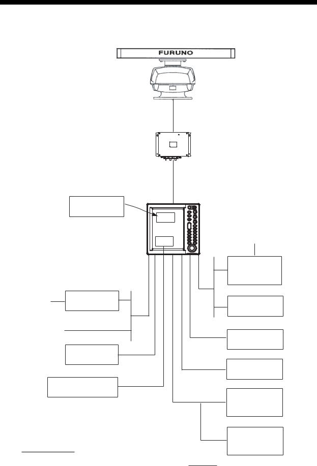
SYSTEM CONFIGURATION
FR-8252
ANTENNA UNIT
RSB-0073-087-XN12A/XN13A
POWER SUPPLY UNIT
PSU-008
|
Auto Plotter |
|
DISPLAY UNIT |
|
ARP-11 |
|
|
|
|
RDP-150 |
|
|
|
|
|
|
(built in display unit) |
|
|
|
|
RGB |
Gyrocompass |
|
|
|
|
|
|
|
Gyro |
|
|
|
Converter |
|
|
|
AD-100 |
100/110/ |
Rectifier |
|
Heading Sensor |
RU-3423 |
|
||
115/220/ |
|
PG-1000 |
|
|
|
||
230 VAC, 1φ |
|
|
|
12-24 VDC |
|
NMEA |
|
|
|
|
|
|
Remote |
|
Device |
|
|
|
|
|
Display |
|
NMEA |
|
|
|
|
|
|
|
Device |
|
Commerical Monitor* |
|
|
|
(SVGA or better) |
|
External |
|
|
|
|
|
|
|
Buzzer |
|
|
|
OP03-136 |
OR
Category of units
Antenna unit: Exposed to weather All other units: Protected from weather
Remote
Controller
RCU-019
: Optional equipment
xi
SYSTEM CONFIGURATION
FR-8122, FR-8062
ANTENNA UNIT
RSB-0070-085-XN12A: FR-8062
RSB-0073-085-XN12A/XN13A: FR-8062
RSB-0073-086-XN12A/XN13A: FR-8122
Auto Plotter
ARP-11
DISPLAY UNIT
RDP-150
(built in display unit)
Rectifier 100/110/ RU-3423 115/220/
230 VAC, 1φ
12-24 VDC
Remote
Display
Commerical Monitor*
(SVGA or better)
Category of units
Antenna unit: Exposed to weather All other units: Protected from weather
RGB |
Gyrocompass |
|
Gyro
Converter
AD-100
Heading Sensor
PG-1000
NMEA
Device
NMEA
Device
External
Buzzer
OP03-136
OR
Remote
Controller
RCU-019
: Optional equipment
xii
1.OPERATIONAL OVERVIEW
1.1Controls
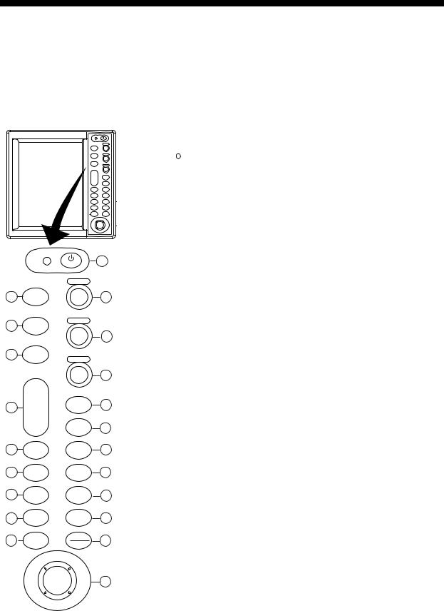
1.1.1Display unit
This radar is operated with the controls of the display unit (and the remote controller), which includes 18 keys that are labeled with their functions, three knob controls and a trackball. When you correctly execute an operation, the unit generates a beep. Invalid operation causes the unit to emit several beeps.
|
BRILL |
|
|
GAIN |
|
STBY |
|
|
TX |
|
|
|
PUSH AUTO/MAN |
|
MODE |
A/C SEA |
|
|
||
CUSTOM |
PUSH AUTO/MAN |
|
A/C RAIN |
||
|
||
|
PUSH AUTO/MAN |
|
+ |
F1 |
|
RANGE |
||
- |
|
|
|
F2 |
|
ZOOM |
OFF |
|
CENTER |
||
TARGET |
TRAILS |
|
ALARM |
||
EBL |
VRM |
|
MENU |
TLL |
|
ENTER |
CANCEL |
|
HL OFF |
|
|
BRILL |
1 |
|
|
GAIN |
|
2 |
STBY |
|
11 |
TX |
|
||
|
|
|
|
|
|
PUSH AUTO/MAN |
|
3 |
MODE |
A/C SEA |
|
|
12 |
||
|
|
|
|
4 |
CUSTOM |
PUSH AUTO/MAN |
|
A/C RAIN |
|
||
|
|
|
|
|
|
|
13 |
|
|
PUSH AUTO/MAN |
|
5 |
+ |
F1 |
14 |
RANGE |
|||
|
- |
|
|
|
|
F2 |
15 |
6 |
ZOOM |
OFF |
16 |
CENTER |
|||
7 |
TARGET |
TRAILS |
17 |
ALARM |
|||
8 |
EBL |
VRM |
18 |
9 |
MENU |
TLL |
19 |
10 |
ENTER |
CANCEL |
20 |
HL OFF |
|||
|
|
|
21
No. |
|
|
Control |
Description |
|
|
|
|
|
1 |
|
|
/BRILL |
Momentary press: Turns power on; adjusts |
|
|
|||
|
|
|||
|
|
|
|
brilliance. |
|
|
|
|
Long press: Turns power off. |
|
|
|
|
Note: Hereafter this control is referred to as |
|
|
|
|
“POWER/BRILL”. |
|
|
|
|
|
2 |
STBY/TX |
Transmits radar pulses and places radar in |
||
|
|
|
|
stand-by alternately. |
|
|
|
|
|
3 |
MODE |
Chooses presentation mode. |
||
|
|
|
|
|
4 |
CUSTOM |
Presets radar controls for one-touch set up of |
||
|
|
|
|
radar. |
|
|
|
|
|
5 |
RANGE |
Chooses radar range. |
||
|
|
|
|
|
6 |
ZOOM |
Zooms chosen location (or target). |
||
|
|
|
|
|
7 |
TARGET |
Sets target alarm, which watches for targets |
||
|
ALARM |
entering (or exiting) an alarm zone. |
||
|
|
|
|
|
8 |
EBL |
Measures bearing to a target. |
||
|
|
|
|
|
9 |
MENU |
Opens/closes menu. |
||
|
|
|
|
|
10 |
ENTER |
Saves chosen menu option; acquires ARP tar- |
||
|
|
|
|
get; chooses ARP or AIS target to display its |
|
|
|
|
data. |
|
|
|
|
|
11 |
GAIN |
Adjusts the sensitivity of the radar receiver. |
||
|
|
|
|
|
12 |
A/C SEA |
Suppress sea clutter. |
||
|
|
|
|
|
13 |
A/C RAIN |
Suppresses rain clutter. |
||
|
|
|
|
|
14, 15 |
F1, F2 |
Function keys providing instant call up of |
||
|
|
|
|
desired function. |
|
|
|
|
|
16 |
OFF CENTER |
Shifts display. |
||
|
|
|
|
|
17 |
TRAILS |
Plots radar echo movement. |
||
|
|
|
|
|
18 |
VRM |
Measures range to a target. |
||
|
|
|
|
|
19 |
TLL |
Outputs latitude and longitude position of a tar- |
||
|
|
|
|
get to a navigation plotter or inscribes mark at |
|
|
|
|
cursor location, or both the above. |
|
|
|
|
|
20 |
CANCEL/ |
Temporarily erases heading line; cancels last |
||
|
HL OFF |
entry in menu operation; cancels tracking of |
||
|
|
|
|
ARP target; removes data of selected ARP or |
|
|
|
|
AIS target from data box; goes back one layer |
|
|
|
|
in multilayer menu. |
|
|
|
|
|
21 |
Trackball |
Chooses menu items and options; shifts |
||
|
|
|
|
cursor. |
|
|
|
|
|
1-1
1. OPERATIONAL OVERVIEW
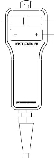
1.1.2Remote controller
The optional remote controller provides armchair control over transmit, standby, range and display offcentering (30% in stern direction).
Offcenters display.
OFF STBY CENTER TX
Toggles STBY/TX.
RANGE |
Chooses range. |
Remote controller
1-2
1. OPERATIONAL OVERVIEW
1.2Turning the Radar On/Off, Transmitting
Press the POWER/BRILL key at the top of the control panel to turn the radar on, and the lamp to its left lights. To turn the radar off, press and hold down the key until the screen turns black.
At power-up, the start-up screen appears, showing the model name, program number and the results of the ROM and RAM check, OK or NG (No Good). If an NG appears, try pressing any key other than the power key to proceed. If normal operation is not possible, contact your dealer for advice.
12.1" COLOR LCD
MARINE RADAR
F R - 8 x x 2 |
|
Model name appears here. |
|
|
|||
ROM: OK |
RAM: OK |
|
|
Program No. 0359226-xx.xx
FURUNO ELECTRIC CO., LTD.
Start-up screen
After the tests are completed, the bearing scale and a digital timer appear. The digital timer counts down the time remaining to warm up the magnetron, which transmits the radar pulses. This warmup takes 180 sec. (FR-8252) or 90 sec. (FR-8062, FR-8122).
After the timer has counted down to 0:00, the STBY screen appears, the appearance of which you may choose according to your needs. (For further details, see paragraph 1.41.2.) The radar is now ready to transmit radar pulses. Press the STBY/TX key to transmit radar pulses.
The STBY/TX key toggles between stand-by and transmit status. The antenna rotates in transmit condition and is stopped in standby. Because the magnetron ages with use it is highly recommended to set the radar in standby when it will not be required for an extended period of time, to extend the life of the magnetron.
Quick start
Provided that the radar was once in use with the transmitter tube (magnetron) still warm, you can get the radar into TRANSMIT condition without the warm-up. If the POWER/BRILL key was turned off by mistake or the like and you wish to restart the radar promptly, turn on the POWER/ BRILL key not later than 10 seconds after power-off. This feature is not available with the
FR-8252.
1-3

1. OPERATIONAL OVERVIEW
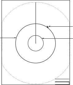
1.3Display Indications
Presentation mode
Auto adjustment of rain and sea clutters
Range ring interval
Offcenter |
Heading North Marker |
(M: Manual, A: Auto) |
|
Range |
0.75 |
0.25 |
359.9° M |
TUNE AUTO |
TUNE indicator |
|
NM |
||||||
Pulse length |
SP |
|
GAIN AUTO |
|||
OFFCENTER(M) |
|
GAIN indicator |
||||
H UP |
|
SEA AUTO |
||||
Custom setting name |
|
|
A/C SEA indicator |
|||
HARBOR A/C AUTO |
|
RAIN AUTO |
||||
Echo stretch (ES), |
|
|
|
A/C RAIN indicator |
||
ES 1 |
EAV1 |
|
|
|||
|
2ND ECHO |
2nd echo rejector |
||||
Echo averaging (EAV) |
NR LOW |
|
||||
|
ZOOM |
Zoom |
||||
IR LOW |
|
|||||
|
WATCH |
|||||
Noise rejector (NR), |
|
|
|
|
||
|
|
|
|
WATCHMAN |
||
Interference rejector (IR) |
|
|
|
|
||
|
|
|
|
Target alarm zone 1 |
||
Origin mark |
|
|
|
|
|
|
Dashed: relative |
|
|
|
|
No. 2 EBL |
|
Solid: true |
|
|
|
|
|
|
|
|
|
|
|
Heading line |
|
Bearing scale |
|
|
|
|
|
|
No. 1 VRM |
|
|
|
|
No. 2 VRM |
|
No. 1 EBL |
|
|
|
|
Range ring |
|
|
|
|
|
|
||
Zoom cursor |
|
|
|
|
|
|
Cursor |
+ |
|
|
|
Zoom window |
|
|
|
|
|
|||
|
|
|
|
|
||
|
|
|
|
|
Target alarm zone 2 |
|
Trail reference |
TRAILS (T) |
|
ALARM1_IN |
Target alarm |
||
Trail time |
15S |
|
|
ALARM2_OUT |
indications |
|
No.1 EBL bearing |
EBL1>270.0°R< |
+ 242.8°R 2.782 NM |
VRM1>0.425<NM |
No. 1 VRM range |
||
No. 2 EBL bearing |
EBL2 |
45.0°R |
VRM2 0.220NM |
No. 2 VRM range |
||
|
|
|
|
|
||
|
|
|
|
|
|
|
|
|
OWN |
LAT: 34°56.123 N |
CURSOR LAT: 34°56.123 N |
WAY |
14.90 NM |
TEMP |
12.3°C |
Cursor data |
|
SHIP |
LON: 135°34.567 E |
LON: 135°34.567 E |
POINT |
202.4° |
|
|
||
|
SPEED 12.3 kt |
TTG: 01:00 |
|
TTG: 00:20 |
DEPTH |
56.7 m |
(Range and bearing or L/L position) |
|
|
|
|
|
|||||
Nav data: Appears at screen bottom when Data Box in the |
||||||||
Display sub menu is set to "Nav" or "All". Appropriate sensors required to display nav data.
Display indications
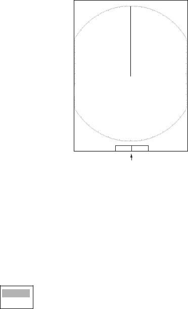
The screen configuration, chosen Note during the installation, is available in three types, “Sea”, “River” and “IEC”, and the default configuration
is “Sea”. The majority of the descriptions in this manual use the “Sea” configuration. The major difference between the Sea, River and IEC configurations is the effective display area - it is elliptical on the Sea and River types and circular on the IEC type.
|
330 |
000 |
|
030 |
|
300 |
|
060 |
270 |
|
090 |
240 |
|
120 |
|
210 |
150 |
|
|
180 |
Bearing scale for Sea and |
Bearing scale for |
|
River configurations |
IEC configuration |
|
1-4
1. OPERATIONAL OVERVIEW
1.4Adjusting Display Brilliance, Panel Dimmer
The display brilliance and panel dimmer may be adjusted as follows:
1. Press the POWER/BRILL key momentarily to show the Brill/Panel dialog box.
Brill/Panel
W Min Max X
Brill (1 - 15) 15 


Panel (1 - 15) 15


[ENTER]: Select
[CANCEL/HL OFF]: Close
Brill/Panel dialog box
2.Press the ENTER key to choose Brill or Panel, whichever you wish to adjust.
3.Roll the trackball rightward or leftward to adjust. (For brilliance, you may also use the POWER/ BRILL key.)
4.Press the CANCEL/HL OFF key to close the window.
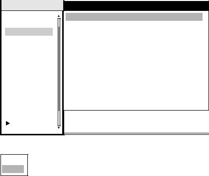
1.5Menu Overview
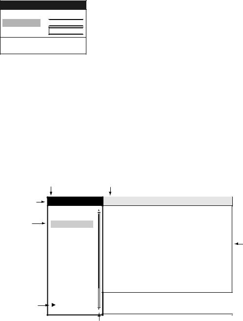
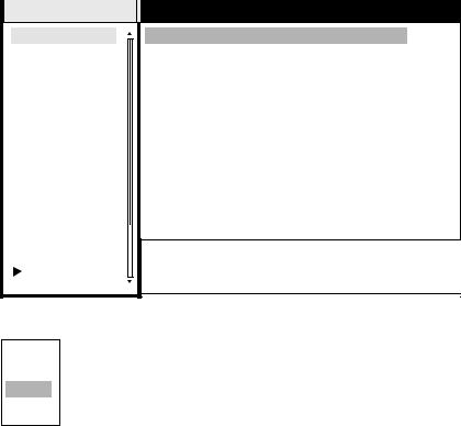
Less-often used functions are controlled through the menu, which consists of 15 menus and 5 sub menus. Below is the basic procedure for menu operation.
1. Press the MENU key to display the menu.
Menu |
Currently selected menu |
Title bar*4 |
Menu |
Echo |
|
|
|
Brill/Color |
Auto Gain |
:Moderate |
|
Cursor*4 |
Display |
Auto Sea |
:Moderate |
|
Echo |
Auto Rain |
:Moderate |
|
|
|
Target Trails |
Pulse Length |
:Long |
|
|
Mark |
Echo Stretch |
:Off |
|
|
Custom 1 |
Echo Average |
:Off |
Menu items |
|
Custom 2 |
Noise Rejector |
:Off |
and current |
|
Custom 3 |
Interference Rejector |
:Med |
settings |
|
Tuning |
Auto Anti Clutter |
:Off |
|
|
|
|||
|
GPS Buoy |
Display-Dynamic |
:Normal |
|
|
Target |
Display-Curve |
:2 |
|
|
ARP*1 |
Antenna Speed |
:48rpm |
|
|
AIS*2 |
2nd Echo Rejector |
:Off |
|
|
GPS*3 |
[ENTER]: Enter [CANCEL/HL OFF]: Back |
|
|
Arrow means |
System |
[MENU]: Exit |
|
|
sub menus |
|
|
|
|
present |
|
Scroll bar |
|
|
|
|
|
|
|
|
|
(Indicates menus not currently shown in menu window. |
|
|
|
|
Black vertical line indicates location in menu.) |
|
|
*1 Displayed if equipped with ARP Board.
*2 Displayed if radar is interfaced with AIS transponder. *3 Dipslayed if radar is interfaced with GPS receiver.
*4 Title bar is currently controllable column is blue; selected cursor is yellow. Title bar of inactive column is gray.
Menu
2.Roll the trackball to choose a menu or sub menu. As you roll the trackball, the yellow (highlight) cursor in the Menu column indicates the menu currently selected and the menu items change according to the menu selected.
1-5

1. OPERATIONAL OVERVIEW
Menu description
Brill/Color: Choose colors; adjust range ring brilliance. DIsplay: Control display functions.
Echo: Adjust radar echo.
Target Trails: Process target trails.
Mark: Process markers such as VRM and EBL.
Custom 1-Custom 3: One-touch set up for given navigation situation. Tuning: Adjust radar tuning.
GPS Buoy: Set up GPS buoy display. Target: Set up ARP and AIS targets. ARP: Set up ARP display.
AIS: Set up AIS display.
GPS: Set up FURUNO GPS receiver interfaced with this radar.
System:
Initial: Initial settings.
Factory: System diagnostic and LCD test.
Installation: Items for installation. Not accessible by user.
Sector Blank 1, Sector Blank 2: Set up for preventing transmission in a certain area.
3.Press the ENTER key to switch control to the menu items column. At this time the cursor in the menu column turns gray and the cursor in the menu items column is yellow, indicating that control is now with the menu items column.
To switch control between the menu column and menu items column, use the CANCEL/HL OFF key. The color of the title bar of the active column is blue and the color of the title bar of the inactive column is gray.
4.Roll the trackball to choose the menu item desired and press the ENTER key. A window with options for the corresponding menu item appears. For example, the window below shows the options for Color in the Target Trails menu.
Green
Red
Blue
White
Black
5.Roll the trackball upward or downward to choose appropriate option.
6.Press the ENTER key to save your selection. To close the window without saving, press the CANCEL/HL OFF key (instead of the ENTER key).
7.Press the MENU key to close the menu.
Note
The menus on the IEC-type radar close automatically when there is no menu operation for 10 seconds, as per IEC regulations. The following menus and screens however are exempt from this rule: Alarm message, GPS self test, Satellite monitor, Diagnostic, LCD pattern, tuning initial adjust and auto installation setup.
Menus do not close automatically in the “River” or “Sea” configuration.
1-6
1. OPERATIONAL OVERVIEW
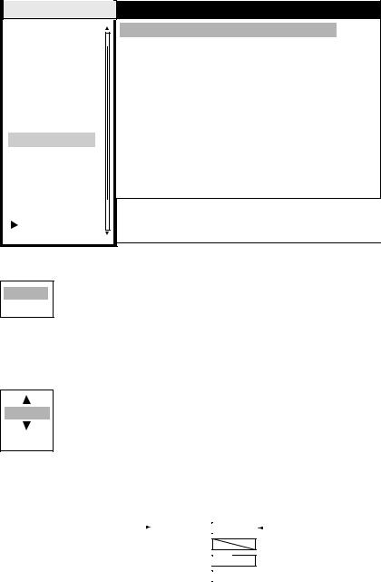
1.6Tuning
The radar receiver can be tuned automatically or manually, and the default tuning method is automatic. If you require manual tuning, do the following:
1.Use the RANGE key to choose the 48-mile range.
2.Press the MENU key to display the main menu.
3.Use the trackball to choose Tuning and press the ENTER key.
Menu |
Tuning |
|
Brill/Color |
Tuning Mode |
:Auto |
Display |
Manual Tuning |
:2048 |
Echo |
|
|
Target Trails |
|
|
Mark |
|
|
Custom 1 |
|
|
Custom 2 |
|
|
Custom 3 |
|
|
Tuning |
|
|
GPS Buoy |
|
|
Target |
|
|
ARP |
|
|
AIS |
|
|
GPS |
[ENTER]: Enter [CANCEL/HL OFF]: Back |
|
System |
[MENU]: Exit |
|
4. Use the trackball to choose Tuning Mode and press the ENTER key.
Auto
Manual
Tuning options
5.Choose Manual and press the ENTER key.
6.Choose Manual Tuning and push the ENTER key. The window shown below appears.
2048
(0-4095)
7.Roll the trackball upward or downward to adjust the tuning, watching the tuning bar at the top right corner. The best tuning point is where the tuning bar swings maximum. The vertical bar on the tuning bar shows tuning control position; not the tuning condition.
|
|
|
|
|
|
|
|
|
|
|
|
|
|
Tuning method (Manual) |
|
TUNE MAN |
|
|
|
|
|
|
|
|
|
Tuning bar |
|
|
|
|
|
|
|
|
|
|
|||||
|
|
|
|
|
|
|
|
|
|||||
|
|
|
GAIN AUTO |
|
|
|
|||||||
|
|
|
|
|
|
|
|
|
|
|
|
||
|
|
|
SEA AUTO |
|
|
|
|
|
|
||||
|
|
|
RAIN AUTO |
|
|
|
|
|
|
||||
|
|
|
|
|
|
|
|
|
|
||||
|
|
|
|
|
|
|
|
|
|
|
|
|
|
Tuning indicator
8.Push the ENTER key.
9.Press the MENU key to close the menu.
1-7

1. OPERATIONAL OVERVIEW
1.7Presentation Modes
This radar has the following presentation modes:
Relative Motion (RM)
Head-up: Unstabilized display. Heading is at the top of the screen.
Course-up: Compass-stabilized relative to ship's orientation. The bearing scale rotates to place ship’s heading (course set) at the screen top at the moment the course-up mode is selected.
North-up: Compass-stabilized with reference to north. Bearing scale is fixed.
True Motion (TM)
North-up: Ground or sea stabilized with compass and speed inputs. Own ship moves on the display. Landmasses and sea are fixed.
1.7.1Choosing presentation mode
Press the MODE key consecutively to choose presentation mode desired. The presentation mode in use appears at the top left corner on the screen.
All modes except head-up require a heading signal, in AD-10 format or NMEA Note format. If the heading signal is lost, the mode is changed to head-up and the north
marker disappears. Further, the heading readout shows XXX.X and the message “GYRO” (AD-10 format data) or “NMEA-HEAD” (NMEA format data) appears in the alarm message display. Restore gyro input and confirm bearing.
1.7.2Description of presentation modes
Head-up mode
|
North Marker |
Heading Line |
The head-up mode is a display in which the line con- |
|
|
|
|
|
necting own ship and the top of the display indicates own |
|
|
ship's heading. |
|
|
The target pips are painted at their measured distances and in their directions relative to own ship's heading. Echoes (other than landmass) may be unstable if ship’s yawing and turning are severe.
A short line on the bearing scale is the north marker, indicating heading sensor north.
1-8
|
1. OPERATIONAL OVERVIEW |
Course-up mode |
Heading Line |
North Marker |
The course-up mode is an azimuth stabilized display in which a line connecting the center with the top of the display indicates own ship's intended course (namely, own ship's previous heading just before this mode has been selected).
Target pips are painted at their measured distances and in their directions relative to the intended course, which is maintained at the 0- degree position. The heading line moves in accordance with ship's yawing and course change. This mode is useful to avoid smearing of picture during course change.
North-up mode
The north-up mode paints target pips at their measured distances and in their true (heading sensor) directions from own ship, north bearing maintained at the top of the screen. The heading line changes its direction according to the ship's heading.
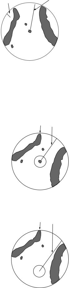
True motion mode
Own ship and other moving objects move in accordance with their true courses and speed. In ground stabilized TM, all fixed targets, such as landmasses, appear as stationary echoes.
When own ship reaches a point corresponding to 75% of the radius of the display, own ship position is automatically reset to a point of 75% radius opposite to the extension of the heading line passing through the display center. You may also reset the own ship symbol manually by pressing the OFF CENTER key. The method of resetting is the same as mentioned above.
North Marker |
Heading Line |
North Marker |
Heading Line |
|
1-9
1. OPERATIONAL OVERVIEW
Automatic resetting of own ship marker in true motion mode
North
marker
Heading line 

(a) True motion |
(b) Own ship has reached a |
is selected |
point 75% of display radius |
(c) Own ship is automatically reset to 75% of radius
1.8Choosing a Range Scale
The selected range scale, range ring interval and pulse length are shown at the upper left corner on the screen. When a target of interest comes closer, reduce the range scale so that it appears in 50-90% of the display radius.
Use the RANGE key to choose range desired. Hit the "+" part of the key to raise the range; the "-" part to lower the range.
1-10
1. OPERATIONAL OVERVIEW
1.9Choosing a Pulse Length
The pulse length in use appears at the top left position on the screen. Appropriate pulse lengths are preset to individual range scales and custom setups. If you are not satisfied with the pulse length setting on the 1.5 nm or 3 nm range, you may change it as below. Use a longer pulse when your objective is long range detection, a shorter pulse when resolution is important.
1.Press the MENU key to open the menu.
2.Use the trackball to choose the Echo menu and press the ENTER key.
Menu |
Echo |
|
|
Brill/Color |
Auto Gain |
:Moderate |
|
Display |
Auto Sea |
:Calm |
|
Echo |
Auto Rain |
:Calm |
|
Target Trails |
Pulse Length |
:Short |
|
Mark |
Echo Stretch |
:1 |
|
Custom 1 |
Echo Average |
:Off |
|
Custom 2 |
Noise Rejector |
:Off |
|
Custom 3 |
Interference Rejector |
:Off |
|
Tuning |
Auto Anti Clutter |
:Off |
|
GPS Buoy |
DIsplay-Dynamic |
:Normal |
|
Target |
DIsplay-Curve |
:1 |
|
ARP |
Antenna Speed |
:48rpm |
|
AIS |
2nd Echo Rejector |
:Off |
|
|
|
||
GPS |
[ENTER]: Enter [CANCEL/HL OFF]: Back |
||
System |
|||
[MENU]: Exit |
|
||
3. Use the trackball to choose Pulse Length and press the ENTER key.
Short
Long
4.Choose Short or Long as appropriate and press the ENTER key.
5.Press the MENU key to close the menu.
1-11

1. OPERATIONAL OVERVIEW
1.10Adjusting the Gain (sensitivity)
The gain functions to adjust the receiver sensitivity for the best reception of signals of widely varying amplitudes.
1.10.1Choosing gain adjustment method
Gain may be adjusted automatically or manually. Push the GAIN control to choose automatic or manual adjustment alternately. The adjustment method currently chosen is show at the top right corner of the screen. In the example below the gain adjustment method is “AUTO”.
TUNE AUTO 
Gain adjustment method (AUTO)  GAIN AUTO
SEA AUTO 
RAIN AUTO 
Gain adjustment method indicator
1.10.2Setting automatic gain level
1.Press the MENU key to open the menu.
2.Choose the Echo menu and press the ENTER key.
3.Choose Auto Gain and press the ENTER key.
Rough
Moderate
Calm
4.Choose the option which best matches current sea condition and press the ENTER key.
5.Press the MENU key to close the menu. Gain is automatically adjusted according to the level selected.
1.10.3Manual gain adjustment
Adjust the gain such that noise faintly appears over the entire screen. If the gain is too low weak echoes will not be displayed and if the gain is too high, weak echoes will be hidden in background noise.
1.Push the GAIN control to show “GAIN MAN” as the gain adjustment method.
2.Rotate the GAIN control to adjust the gain. Adjust the control so background noise is just visible on the screen.
1-12

1. OPERATIONAL OVERVIEW
1.11Suppressing Sea Clutter
Echoes from waves cover the central part of the display with random signals known as sea clutter. The higher the waves, and the higher the antenna above the water, the further the clutter will extend. When sea clutter masks the picture, use the A/C SEA control to suppress the clutter, either manually or automatically.
1.11.1Choosing sea clutter adjustment method
Push the A/C SEA control to choose automatic or manual adjustment alternately. The adjustment method currently chosen is show at the top right corner of the screen. In the example below the sea clutter adjustment method is “AUTO”.
TUNE AUTO 
GAIN AUTO 
A/C SEA adjustment method (AUTO)  SEA AUTO
RAIN AUTO 
A/C SEA indicator
1.11.2Setting automatic sea clutter suppression level
1.Press the MENU key to open the menu.
2.Choose the Echo menu and press the ENTER key.
3.Choose Auto Sea and press the ENTER key.
Rough
Moderate
Calm
4.Choose the option which best matches current sea condition and press the ENTER key.
5.Press the MENU key to close the menu. Sea clutter is automatically adjusted according to the level selected.
1-13
1. OPERATIONAL OVERVIEW
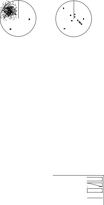
1.11.3Manual sea clutter adjustment
1.Push the A/C SEA control to show “SEA MAN” as the A/C SEA adjustment method.
2.Rotate the A/C SEA control to suppress sea clutter.
The proper setting of the A/C SEA control is such that the clutter is broken up into small dots, and small targets become distinguishable. If the setting is set too low, targets will be hidden in the clutter, while if the setting is too high, both sea clutter and targets will disappear from the display. In most cases adjust the control until clutter has disappeared to leeward, but a little is still visible windward.
Sea clutter at |
A/C SEA control adjusted; |
screen center |
sea clutter suppressed |
Appearance of sea clutter
1.12Suppressing Rain Clutter
The vertical beamwidth of the antenna is designed to see surface targets even when the ship is rolling. However, by this design the unit will also detect rain clutter (rain, snow, or hail) in the same manner as normal targets.
The A/C RAIN control adjusts the receiver sensitivity as the A/C SEA control does but rather in a longer time period (longer range). The higher the setting the greater the anti-clutter effect. When echoes from precipitation mask solid targets, adjust the control to split up these unwanted echoes into a speckled pattern, making recognition of solid targets easier.
1.12.1Choosing rain clutter adjustment method
Rain clutter may be adjusted automatically or manually. Push the A/C RAIN control to choose automatic or manual adjustment alternately. The adjustment method currently chosen is show at the top right corner of the screen. In the example below the rain clutter adjustment method is “AUTO.”
TUNE AUTO 
GAIN AUTO 
SEA AUTO 
A/C RAIN adjustment method (AUTO)  RAIN AUTO

A/C RAIN indicator
1-14
1. OPERATIONAL OVERVIEW
1.12.2Setting automatic rain clutter suppression level
1.Press the MENU key to open the menu.
2.Choose the Echo menu and press the ENTER key.
3.Choose Auto Rain and press the ENTER key.
Rough
Moderate
Calm
4.Choose the option which best matches current sea condition and press the ENTER key.
5.Press the MENU key to close the menu. Rain clutter is automatically adjusted according to the level selected.
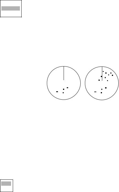
1.12.3Manual rain clutter adjustment
1.Push the A/C RAIN control to show “RAIN MAN” as the A/C RAIN adjustment method.
2.Rotate the A/C RAIN control to suppress the rain clutter.
Rain clutter at |
A/C RAIN control |
screen center |
adjusted |
Appearance of rain clutter
1.13Automatic Suppression of Sea and Rain Clutters
If neither sea clutter or rain clutter are sufficiently suppressed in spite of adjustment of respective controls, turn on the automatic anti clutter feature to suppress them. A/C AUTO appears at the top left corner when this feature is turned on.
1.Press the MENU key to open the menu.
2.Choose the Echo menu and press the ENTER key.
3.Choose Auto Anti Clutter and press the ENTER key.
Off
On
4.Choose Off or On as appropriate and press the ENTER key.
5.Press the MENU key to close the menu.
1-15
1. OPERATIONAL OVERVIEW
1.14Cursor
The cursor functions to find the range and bearing (default function) to a target or the latitude and longitude position of a target. Roll the trackball to position the cursor and read the cursor data at the screen bottom.
3 |
0.5 |
NM |
+ Cursor
+ 110.1°R 2.525 NM
Cursor data
(latitutde and longitude or range and bearing)
Cursor data
Cursor data
Cursor data can be shown as latitude and longitude or range and bearing from own ship to the cursor. Position and heading bearing signal are required.
1.Press the MENU key to open the menu.
2.Choose the Mark menu and press the ENTER key
3.Choose Cursor Position and press the ENTER key.
Rng/Brg
Lat/Lon
4.Choose Brg/Rng or Lat/Long as appropriate and press the ENTER key. (Note that cursor latitude and longitude position cannot be displayed when nav data is displayed.)
5.Press the MENU key to close the menu.
1-16
1. OPERATIONAL OVERVIEW
1.15Interference Rejector
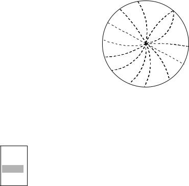
Mutual radar interference may occur in the vicinity of another shipborne radar operating in the same frequency band (9 GHz). It is seen on the screen as a number of bright spikes either in irregular patterns or in the form of usually curved spoke-like dotted lines extending from the center to the edge of the picture. Activating the interference rejector circuit can reduce this type of interference.
Interference
1.Press the MENU key to open the menu.
2.Choose the Echo menu and press the ENTER key.
3.Choose Interference Rejector and press the ENTER key.
Off
Low
Med
High
4.Choose Off, Low, Med or High as appropriate and press the ENTER key. High provides the highest degree of interference rejection.
5.Press the MENU key to close the menu.
Be sure to turn off the interference rejector when no interference exists, so as not to miss small targets.
1-17
1. OPERATIONAL OVERVIEW
1.16Measuring the Range to a Target
The range to a target may be measured three ways: with the fixed range rings, with the cursor (if set to measure range and bearing), and with the VRM.
Use the fixed range rings to obtain a rough estimate of the range to a target. They are the concentric solid circles about own ship, or the sweep origin. The number of rings is automatically determined by the selected range scale and their interval is displayed at the upper-left position of the screen. Count the number of rings between the center of the display and the target. Check the range ring interval and judge the distance of the echo from the inner edge of the nearest ring.
1.16.1Adjusting range ring brilliance
1.Press the MENU key to open the menu.
2.Choose the Brill/Color menu and press the ENTER key.
Menu |
Brill/Color |
|
Brill/Color |
Range Rings Brill |
:High |
Display |
Echo Color |
:Yellow |
Echo |
Display Color |
:Night |
Target Trails |
Background Color |
:Black/Green |
Mark |
|
|
Custom 1 |
|
|
Custom 2 |
|
|
Custom 3 |
|
|
Tuning |
|
|
GPS Buoy |
|
|
Target |
|
|
ARP |
|
|
AIS |
|
|
GPS |
[ENTER]: Enter [CANCEL/HL OFF]: Back |
|
System |
[MENU]: Exit |
|
3. Choose Range Rings Brill and press the ENTER key.
Off
Low
Med
High
4.Choose appropriate brilliance and press the ENTER key.
5.Press the MENU key to close the menu.
1-18
1. OPERATIONAL OVERVIEW
1.16.2Measuring range by the variable range marker (VRM)
There are two VRMs, No. 1 and No. 2, which appear as dashed rings so that you can discriminate them from the fixed range rings. The two VRMs can be distinguished from each other by different lengths of dashes.
1.Press the VRM key to display either of the VRMs. Successively pressing the VRM key toggles the active VRM between No. 1 and No. 2. The currently active marker is enclosed with >.....< in the VRM indication box.
2.Operate the Trackball to align the variable range marker with the inner edge of the target of interest and read its distance at the lower-right corner of the screen. Each VRM remains at the same geographical distance when you operate the RANGE key. This means that the apparent radius of the VRM ring changes in proportion to the selected range scale.
3.You may “anchor” the VRM by choosing it and pressing the ENTER key.
4.To erase a VRM, make it active and press the CANCEL/HL OFF key.
+ |
Target |
No. 1 |
No. 2 |
VRM |
VRM |
|
|
|
VRM1>0.007NM< |
|
|
|
VRM2 0.140NM |
+ 37.4°R |
0.007 NM |

 VRM indications
Measuring range and bearing between two targets with the EBL
1-19
Loading...