


 Loading...
SATELLITE COMPASS
SC-60

9-52 Ashihara-cho,
Nishinomiya, Japan
Telephone : 0798-65-2111
fax |
: 0798-65-4200 |
All rights reserved. |
Printed in Japan |
PUB.No. OME-72480
( KAMI ) SC-60
Your Local Agent/Dealer
FIRST EDITION : FEB. 2001 U1 : FEB. 26,2004
*00080919106*
*00080919106*
* 0 0 0 8 0 9 1 9 1 0 6 *
*OME72480U10*
*OME72480U10*
* O M E 7 2 4 8 0 U 1 0 *

 SAFETY INSTRUCTIONS
Safety Instructions for the Operator
 WARNING
Do not open the equipment.
Only qualified personnel should work inside the equipment.
Do not disassemble or modify the equipment.
Fire, electrical shock or serious injury can result.
Immediately turn off the power at the switchboard if the equipment is emitting smoke or fire.
Continued use of the equipment can cause fire or electrical shock. Contact a FURUNO agent for service.
Do not place liquid-filled containers on the top of the processor unit.
Fire or electrical shock may result if the liquid enters the equipment.
 CAUTION
No one navigation device should ever be solely replied upon for the navigation of a vessel.
Always confirm position against all available aids to navigation, for safety of vessel and crew.
Use the proper fuse.
Use of a wrong fuse can result in damage to the equipment.
Safety Instructions for the Installer
 WARNING
Do not open the cover unless totally familiar with electrical circuits and service manual.
Improper handling can result in electrical shock.
Turn off the power at the switchboard before beginning the installation.
Fire or electrical shock can result if the power is left on.
Do not install the equipment where it may get wet from rain or water splash.
Water in the equipment can cause fire, electrical shock or damage to the equipment.
NOTICE
Observe the following compass safe distances to prevent interference to a magnetic compass:
|
Standard |
Steering |
|
|
Compass |
Compass |
|
Display unit |
0.5 m |
0.3 m |
|
SC-602 |
|||
|
|
||
Processor unit |
1.3 m |
0.8 m |
|
SC-601/601D |
|||
|
|
||
Antenna unit |
0.3 m |
0.3 m |
|
SC-303 |
|||
|
|
||
Antenna unit |
0.3 m |
0.3 m |
|
SC-603 |
|||
|
|
||
DGPS beacon |
0.3 m |
0.3 m |
|
antenna GR-8 |
|||
|
|
||
|
|
|
i
TABLE OF CONTENTS
|
|
|
|
|
..................................................................................................................FOREWORD |
|
iv |
||
SYSTEM CONFIGURATION .......................................................................................... |
v |
|||
EQUIPMENT LIST......................................................................................................... |
vi |
|||
SOFTWARE VERSION LIST........................................................................................ |
vii |
|||
SPECIFICATIONS .................................................................................................... |
SP-1 |
|||
1 |
PRINCIPLE OF OPERATION................................................................................. |
1-1 |
||
2 |
INSTALLATION ...................................................................................................... |
2-1 |
||
|
2.1 |
Mounting Considerations ..................................................................................................... |
2-1 |
|
|
|
2.1.1 |
SC-series antenna unit............................................................................................. |
2-1 |
|
|
2.1.2 Display unit, processor unit...................................................................................... |
2-3 |
|
|
2.2 |
Installing the Antenna Units ................................................................................................. |
2-4 |
|
|
|
2.2.1 |
SC-series antenna unit............................................................................................. |
2-4 |
|
|
2.2.2 |
DGPS antenna unit .................................................................................................. |
2-7 |
|
2.3 |
Installing the Processor Unit ................................................................................................ |
2-9 |
|
|
|
2.3.1 |
Deck mount .............................................................................................................. |
2-9 |
|
|
2.3.2 |
Bulkhead mount ..................................................................................................... |
2-10 |
|
|
2.3.3 Installation on the underside of a desk .................................................................. |
2-12 |
|
|
|
2.3.4 Adjusting for orientation error................................................................................. |
2-14 |
|
|
2.4 |
Installing the Display Unit................................................................................................... |
2-14 |
|
|
|
2.4.1 |
Desktop, overhead mounting ................................................................................. |
2-14 |
|
|
2.4.2 |
Flush mount............................................................................................................ |
2-15 |
|
2.5 |
Wiring ................................................................................................................................. |
|
2-16 |
|
2.6 |
Initial Settings..................................................................................................................... |
2-19 |
|
|
|
2.6.1 Confirming satellite status; choosing mounting method ........................................ |
2-19 |
|
|
|
2.6.2 |
Choosing heading source ...................................................................................... |
2-20 |
|
|
2.6.3 |
Heading data format............................................................................................... |
2-21 |
|
2.7 |
Connection of External Equipment .................................................................................... |
2-22 |
|
|
2.8 |
Installing the DGPS Beacon Receiver Kit.......................................................................... |
2-22 |
|
3 |
OPERATION........................................................................................................... |
3-1 |
||
|
3.1 |
Controls................................................................................................................................ |
3-1 |
|
|
3.2 |
Turning the Power On/Off .................................................................................................... |
3-2 |
|
|
3.3 |
Panel Illumination, Display Contrast.................................................................................... |
3-2 |
|
|
3.4 |
Choosing a Display.............................................................................................................. |
3-3 |
|
|
|
3.4.1 |
Description of displays ............................................................................................. |
3-3 |
|
3.5 |
Alarms |
.................................................................................................................................. |
3-5 |
|
3.6 |
Confirming Satellite Status................................................................................................... |
3-6 |
|
|
3.7 |
GPS Setup ........................................................................................................................... |
3-7 |
|
|
|
3.7.1 Displaying the GPS setup menu.............................................................................. |
3-7 |
|
|
|
3.7.2 GPS SETUP menu description ................................................................................ |
3-7 |
|
ii
3.8 |
Output Data.......................................................................................................................... |
3-8 |
|
|
3.8.1 |
Heading .................................................................................................................... |
3-8 |
|
3.8.2 |
Navigation data ........................................................................................................ |
3-9 |
|
3.8.3 |
Interface ................................................................................................................... |
3-9 |
|
3.8.4 |
Log pulse................................................................................................................ |
3-10 |
|
3.8.5 |
Talker identifier mnemonics ................................................................................... |
3-10 |
3.9 |
System Setup..................................................................................................................... |
3-11 |
|
|
3.9.1 |
Geodetic data......................................................................................................... |
3-11 |
|
3.9.2 |
Units of measurement ............................................................................................ |
3-12 |
|
3.9.3 |
Using local time...................................................................................................... |
3-12 |
|
3.9.4 |
Time format ............................................................................................................ |
3-12 |
|
3.9.5 |
Demonstration mode.............................................................................................. |
3-13 |
3.10 |
DGPS Setup....................................................................................................................... |
3-13 |
|
|
3.10.1 Manual DGPS setup .............................................................................................. |
3-13 |
|
|
3.10.2 Programming user beacon stations ....................................................................... |
3-15 |
|
|
3.10.3 Editing user beacon stations.................................................................................. |
3-16 |
|
|
3.10.4 Erasing individual user stations ............................................................................. |
3-17 |
|
|
3.10.5 Erasing all user beacon stations ............................................................................ |
3-17 |
|
3.11 |
OTHERS Menu .................................................................................................................. |
3-18 |
|
3.12 |
TRIP Menu ......................................................................................................................... |
3-19 |
|
3.13 |
Resetting Distance Run ..................................................................................................... |
3-19 |
|
4 MAINTENANCE, TROUBLESHOOTING............................................................... |
4-1 |
|
4.1 |
Preventive Maintenance ...................................................................................................... |
4-1 |
4.2 |
Troubleshooting ................................................................................................................... |
4-2 |
4.3 |
Diagnostics........................................................................................................................... |
4-2 |
4.4 |
Program Number ................................................................................................................. |
4-5 |
4.5 |
Clearing Data ....................................................................................................................... |
4-5 |
4.6 |
Replacement of Battery ....................................................................................................... |
4-6 |
4.7 |
Replacement of Fuse........................................................................................................... |
4-7 |
4.8 |
Error Messages.................................................................................................................... |
4-7 |
APPENDIX A............................................................................................................... |
A-1 |
Menu Tree..................................................................................................................................... |
A-1 |
Geodetic Chart Codes .................................................................................................................. |
A-2 |
Digital Interface ............................................................................................................................. |
A-3 |
Input/Output Ports...................................................................................................................... |
A-10 |
Parts Location ............................................................................................................................. |
A-11 |
Parts List .................................................................................................................................... |
A-12 |
APPENDIX B Installation of Antenna Unit SC-603................................................... |
B-1 |
PACKING LISTS ......................................................................................................... |
A-1 |
OUTLINE DRAWINGS ................................................................................................ |
D-1 |
INTERCONNECTION DIAGRAMS.............................................................................. |
S-1 |
INDEX................................................................................................................... |
Index-1 |
Declaration of Conformity
iii

FOREWORD
A Word to the Owner of the SC-60
FURUNO Electric Company thanks you for purchasing the FURUNO SC-60 Satellite Compass. We are confident you will discover why the FURUNO name has become synonymous with quality and reliability.
For over 50 years FURUNO Electric Company has enjoyed an enviable reputation for quality and reliability throughout the world. This dedication to excellence is furthered by our extensive global network of agents and dealers.
Your satellite compass is designed and constructed to meet the rigorous demands of the marine environment. However, no machine can perform its intended function unless properly installed and maintained. Please carefully read and follow the operation, installation and maintenance procedures set forth in this manual.
We would appreciate feedback from you, the end-user, about whether we are achieving our purposes.
Thank you for considering and purchasing FURUNO.
Features
The SC-60 is a new satellite compass designed with FURUNO’s advanced GPS kinematic technology. This compass finds a wide range of applications for any type of ships and mobile units at sea or on land.
The main features are
•Perfect for use as heading sensor for Radar/ARPA, AIS, ECDIS, scanning sonar, and video plotter
•There are no mechanical parts such as gimbals or rotating motor, thus the compass is free from routine maintenance
•The performance is not affected by geomagnetism thus it is suitable for use on any vessel
•No need for speed correction like a gyrocompass
•Short settling time - three minutes
•Provides all necessary functions as a GPS navigator.
iv
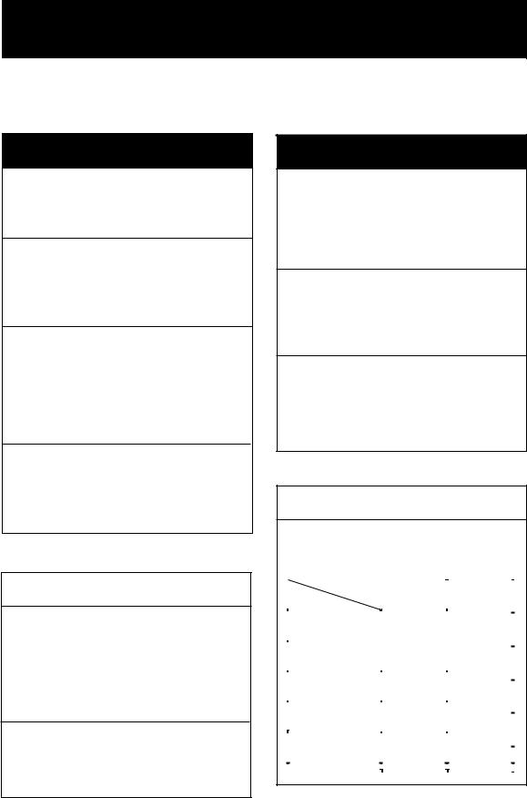
SYSTEM CONFIGURATION
The SC-60 consists of an antenna, a display unit and a processor unit. The antenna is available in a low-profile radome type antenna accommodating three antenna/receiver unit, or discrete type. The tri-antenna system helps reduce the influence of ship's motion (rolling).
DGPS |
|
Antenna Unit |
|
Beacon Antenna |
Antenna Unit |
||
SC-603 |
|||
GR-800-1-S |
SC-303 |
|
|
|
|
OR |
|
|
|
2 |
|
|
|
3 |
Display Unit
SC-602
Speed alarm/ Heading alarm (Contact)
Gyro heading may be supplied through AD-100 Gyro Converter
(For primary gyrocompass and backup SC-60)
or Doppler Speed Log
Beacon Receiver Kit
GR-7001
Processor Unit
SC-601/601-D
12-24 VDC
|
|
|
|
|
|
Radar |
|
|
|
|
|
|
|
|
|
|
|
|
|
|
|
|
|
|
|
|
|
|
|
|
|
|
|
|
|
|
|
|
|
|
|
|
|
|
|
|
Heading |
Autopilot |
|
|
|
|
|
data |
Video Plotter |
|
|
|
|
|
|
Current Indicator |
|
|
|
|
|
|
Scanning Sonar |
|
|
|
|
|
|
ECDIS |
|
|
|
|
|
|
|
|
|
|
|
|
|
|
|
GPS fix, COG, SOG, |
|
|
|
|
||
|
Time/Date, Pitch/Roll |
Radar, |
|
|
|
|
Plotter, etc. |
|
2 ports |
||
|
|
||
|
Option |
|
|
System configuration
v

EQUIPMENT LIST
Standard supply
Name |
Type |
Code No. |
Qty |
Remarks |
|
Antenna Unit |
SC-303 |
─ |
1 |
Radome type |
|
|
SC-603 |
─ |
1 |
Open type |
|
DGPS |
GR-800-1-S |
─ |
1 |
No whip antenna, for SC-601-D |
|
Antenna |
|||||
|
|
|
|
||
Display Unit |
SC-602-E |
─ |
1 |
|
|
Processor Unit |
SC-601 |
─ |
1 |
|
|
SC-601-D |
─ |
With DGPS beacon receiver |
|||
|
|
||||
|
CP08-01602 |
004-377-880 |
1 |
DGPS antenna |
|
|
Parker clamp, spring washer |
||||
|
|
|
|
||
|
|
|
|
GPS antenna |
|
|
CP20-02200 |
000-041-748 |
1 |
CP20-02201, CP20-02202, |
|
Installation |
|
|
|
TPX6-3D2V-15M |
|
CP20-02203 |
─ |
1 |
Display Unit |
||
Materials |
Tapping screw ( 5X20, 4 pcs.) |
||||
|
|
|
|||
|
|
|
|
Processor Unit |
|
|
CP20-02200 |
000-041-748 |
1 |
MJ-A3SPF0013-035 |
|
|
MJ-A6SPF0007-100 |
||||
|
|
|
|
MJ-A7SPF0006-100 |
|
|
|
|
|
CP20-02221 |
|
Accessories |
FP14-02801 |
─ |
1 |
Cover |
|
Spare Parts |
SP20-00901 |
004-377-600 |
1 |
Accessories for Processor Unit |
Optional equipment
Name |
Type |
Code No. |
Qty |
|
Remarks |
|
|
MJ-A6SPF0003-050 |
000-117-603 |
1 |
For AD-10 output, |
||
|
connector at one end, 5 m |
|||||
|
|
|
|
|||
|
|
|
|
For AD-10 output, |
||
|
MJ-A6SPF0007-100 |
000-125-237 |
1 |
connector at both ends, 10 |
||
Cable Assy. |
|
|
|
m |
|
|
MJ-A6SPF0012-100 |
000-133-817 |
1 |
Cross for NMEA output, 10 |
|||
|
||||||
|
m |
|
||||
|
|
|
|
|
||
|
|
|
|
For beacon/log/alarm |
||
|
MJ-A7SPF0003-050 |
000-136-730-01 |
1 |
signal output, connector at |
||
|
|
|
|
one end, 5 m |
||
Antenna |
CP20-01700 |
004-372-110 |
1 |
30 m |
3 pcs., for |
|
Cable Set |
CP20-01710 |
004-372-120 |
50 m |
SC-303 |
||
|
||||||
DGPS Beacon |
GR-7001-K |
000-041-738 |
1 |
|
|
|
Receiver Kit |
|
|
|
|
|
|
Whip Antenna |
FAW-1.2 |
000-130-046 |
1 |
1.2 m |
|
|
Whip Antenna |
04S4176 |
000-112-845 |
1 |
2.6 m |
|
|
Flush Mount F |
OP20-29 |
000-041-405 |
1 |
For display unit |
||
Flush Mount S |
OP20-17 |
000-040-720 |
1 |
For display unit |
||
Extension |
OP08-15-30 |
004-396-440 |
1 |
For DGPS, 30 m |
||
Cable |
OP08-15-60 |
004-396-450 |
For DGPS, 60 m |
|||
|
||||||
Antenna |
OP08-17 |
004-392-510 |
1 |
For DGPS |
||
Cable Set |
||||||
|
|
|
|
|
||
vi
SOFTWARE VERSION LIST
|
|
DISPLAY UNIT: |
205-1312-009 |
PROCESSOR UNIT: |
205-1311-016 |
GPS1: |
205-1313-004 |
GPS2: |
205-1313-004 |
GPS3: |
205-1313-004 |
DGPS: |
085-0182-002 |
vii
This page is intentionally left blank.
SPECIFICATIONS OF SATELLITE COMPASS
SC-60
1 |
GENERAL |
|
1.1 |
Receiver Type |
12 discrete channels |
1.2 |
Rx Frequency |
1575.42 MHz |
1.3 |
Rx Code |
C/A code |
1.4 |
Position Fixing System |
All-in-view, 8-state Kalman filter |
1.5 |
Position Accuracy |
10 m, or 5 m (DGPS), 95% of the time |
1.6 |
Heading Accuracy |
±1.0° (95%) |
1.7 |
Follow-up |
25°/s rate-of-turn |
1.8 |
Settling Time |
3 minutes |
2 |
DISPLAY UNIT |
|
2.1 |
Display Type |
4.5 inch monochrome LCD, 120 x 64 dots |
2.2 |
Effective Area |
60 mm (H) x 95 mm (W) |
2.3 |
Contrast |
64 steps |
2.4 |
Display Mode |
Heading, Nav data, Steering, Compass rose, Rate of turn and Speed |
|
|
modes |
3 |
INTERFACE |
|
3.1 |
Heading Data Output |
3 ports: AD-10 or IEC 61162-1 |
|
|
1 port: NMEA 0183 (Ver1.5/2.0) |
|
|
IEC 61162 Sentences: HDT, HDM, VTG, ZDA, GGA, ROT |
3.2 |
COG, SOG, L/L Output |
1 port: IEC 61162-1 |
|
|
1 port: RS-232C level |
|
|
IEC 61162 Sentences: VTG, GGA, ZDA, GLL, ROT |
|
|
ATT (Proprietary): incl. pitch, roll and yaw data |
|
|
$PFEC,GPatt,xxx.x,+xx.x,+xx.x<CR><LF> (Ver. 1.5) |
|
|
$PFEC,GPatt,xxx.x,+xx.x,+xx.x*hh<CR><LF> (Ver. 2.0) |
3.3 |
Log Output |
1 port: 200/400 pulse/nm (closure signal) |
3.4 |
Alarm Output |
1 port: Alarm signal (closure signal) |
3.5 |
Heading Data Input |
1 port: Backup Heading (AD-10/ IEC 61162 format) from external |
|
|
heading device |
|
|
Sentences: HDT, HDG, HDM |
|
|
(VBW, VHW, VLM for tide direction and speed) |
3.6 |
Beacon Data Input |
1 port; RTCM SC-104 format for RS-232C |
|
|
Sentences: MSK, GGA |
SP - 1 |
E7248S01F |
4 POWER SUPPLY
12-24 VDC: 1.1-0.5 A
5 ENVIRONMENTAL CONDITION AND EMC
5.1Ambient Temperature
|
Display/Processor Unit |
-15°C to +55°C, Designed for protected area |
|
Antenna Unit |
-25°C to +70°C, Designed for exposed area |
5.2 |
Damp Heat |
93%±3% at 40°C |
5.3 |
Waterproofing |
|
|
Antenna Unit |
IPX6 |
|
Display Unit |
IPX5 |
|
Processor Unit |
IPX0 |
5.4 |
Vibration |
IEC 60945 |
5.5 |
EMC |
IEC 60945 |
6 |
COATING COLOR |
|
6.1 |
Display/Processor Unit |
Panel: N3.0 Newtone No.5 (dark gray) |
|
|
Cover: 2.5GY5/1.5 (light gray) |
6.2 |
Antenna Unit |
N9.5 (white) |
SP - 2 |
E7248S01F |
1 PRINCIPLE OF OPERATION
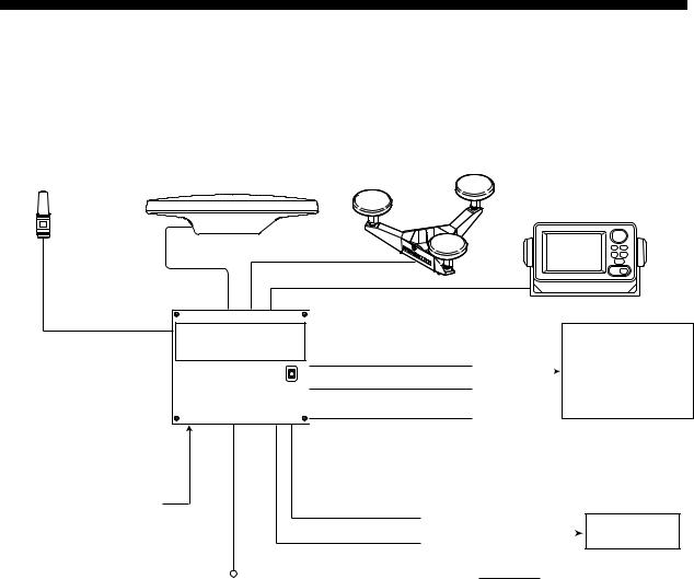
Own ship's heading can be determined by decoding the data in the carrier frequency in addition to ordinary GPS parameters. In principle, a pair of two antennas A1(ref) and A2(fore), each connected with an associated GPS engine and processor, are installed along the ship's fore-and-aft line. GPS systems at A1 and A2 calculate the range and azimuth to the satellite. Difference in range between A1 and A2 is ∆λ + nλ where λ is 19 cm. “n” is automatically found during the initialization stage by receiving three satellites. A fraction of a carrier wavelength, ∆λ , is processed by FURUNO’s advanced kinematic technology in geographical survey, thus determining a vector (range and orientation) A1 to A2.
In reality, a third antenna is used to reduce the influence of pitch, roll and yaw, and five satellites are processed to process 3D data. If the GPS signal is blocked by a tall building or the vessel is under a bridge, the 3-axis solid-state angular rate gyros in the processor unit take place of the satellite compass, maintaining the current heading continuously.
Antenna A3
∆λ
Heading |
|
line |
|
-aft |
|
|
|
|
|
-and |
|
θ |
Fore |
|
|
|
nλ
λ
Vector |
to |
|
decide
heading |
Antenna A2 |
|
Difference between the range from satellite to antenna 1 and the range to antenna 2.
Antenna A1
Principle of satellite compass operation
1-1
This page is intentionally left blank.
2 INSTALLATION
2.1Mounting Considerations
2.1.1SC-series antenna unit
General
•Keep the length of antenna cable in mind when selecting a mounting location. The cable comes in lengths of 15 meters (standard supply), or 30 m or 50 m (optional lengths).
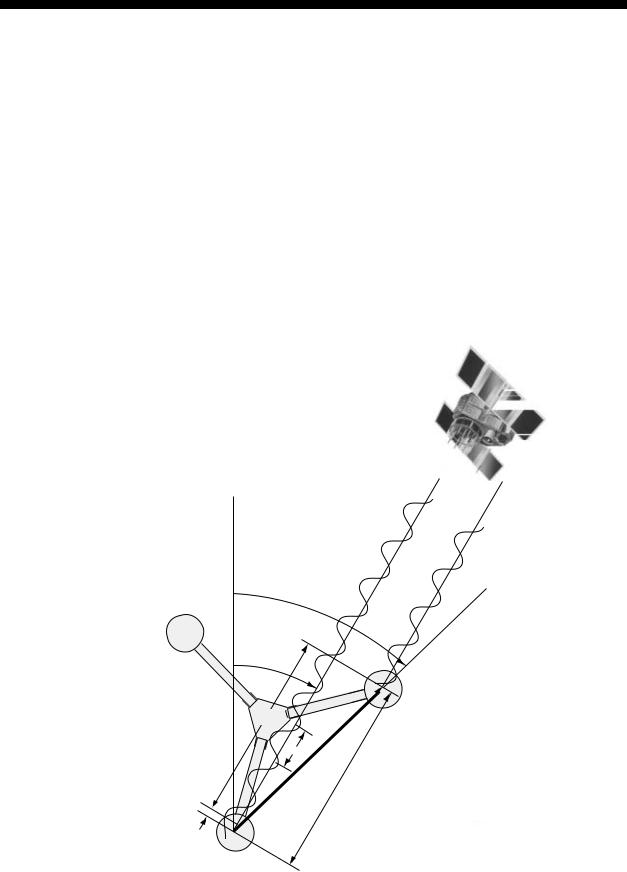
Installing the antenna above superstructures
•The antenna must be mounted above all other structures on the vessel to obtain an unobstructed view of the satellites regardless of vessel heading. Failure to do so will cause shadows and multipath reflection problems.
Mast

 SC-series Antenna


 Radar
Radar Antenna
Bridge
Example of antenna installed above all superstructures
Installing the antenna below superstructures
If it is not possible to mount the antenna above all superstructures on the vessel, as shown in the illustration above, shading and multipath problems may occur on at least one heading, and possibly more. To possibly avoid those problems, observe the guidelines in this section.
NOTICE
If the antenna is installed below any superstructure, the installation must
be done over a two-day period, following the procedure in the service manual.
At least 12 hours are required to capture tracking data to measure multipath indexes and locate areas of shading.
2-1
2.INSTALLATION
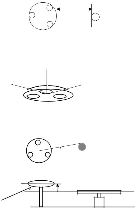
•The horizontal separation between the antenna and masts must be as follows:
Mast diameter |
Separation distance (minimum) |
10 cm |
1.5 m |
30 cm |
3 m |
SC-60’s antenna
Horizontal separation distance
Mast, etc.
Horizontal separation between antenna and masts
•The field of view above the antenna should be as shown below, ±80° against zenith. To avoid reflections from masts and the like, locate the antenna well away from the shadows of the radar mast, etc.
Zenith
-80° +80°
 SC-series antenna
SIDE VIEW
Antenna and field of view
•Referring to the illustration below, locate the antenna away from objects which might block reception, such as a mast.
Mast, etc.
Less than 10°
TOP VIEW
• Locate the antenna unit above the radar antenna, out of the radar beam.
SC-series Antenna
Radar Antenna
2-2
Location influenced |
Radar Antenna |
|
by reflected wave. |
||
|
SC-series |
Reception blocked by mast. |
|
|
Antenna |
|
|
Bridge |
Example of antenna installed below superstructures
2.1.2Display unit, processor unit
•Choose a location where vibration and shock are minimal.
•Install the units well away from locations subject to rain and water splash.
•Locate the units away from air conditioner vents.
•Keep the units out of direct sunlight because of heat that can build up inside their cabinets.
•Choose a well-ventilated location.
•For the display unit, choose a location where it can be easily operated.
•Leave sufficient space around the units to permit access for maintenance. See the outline drawing for recommended maintenance space.
2-3
2. INSTALLATION
2.2Installing the Antenna Units
2.2.1SC-series antenna unit
NOTICE
Fasten the antenna to the mounting location lastly if it is more convenient to connect the antenna cable before mounting the antenna unit.
1.Prepare a mounting platform (wood, steel or aluminum) in accordance with the illustration shown below. If corrosive material is used, take necessary anti-corrosion measures.
Note: When drilling holes in the platform, be sure they are parallel with the fore-and-aft line.
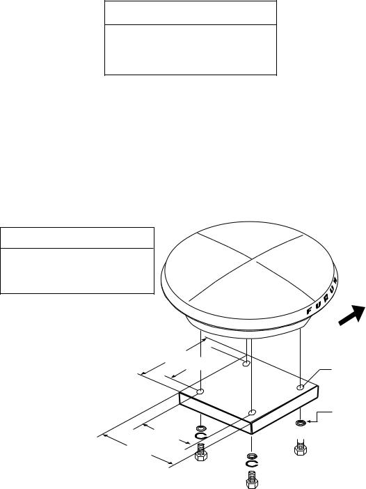
2.Fasten the antenna unit to the platform with four sets of M10 hex. bolts, spring washers and flat washers, orienting it as shown below. (The bow mark
( ) on the antenna should face the bow.) The torque for the hex. bolts should be between 19.6-24.5 Nm.
 NOTICE
Do not open the antenna.
This installation does not require removal of the antenna cover.
240 160 
160
240
 N
N
U
R
F |
U |
|
BOW
Fixing Hole (f11 mm)
Flat Washer

 Spring Washer

 Hex. Bolt
Mounting dimensions for antenna, orienting the antenna
2-4
2. INSTALLATION
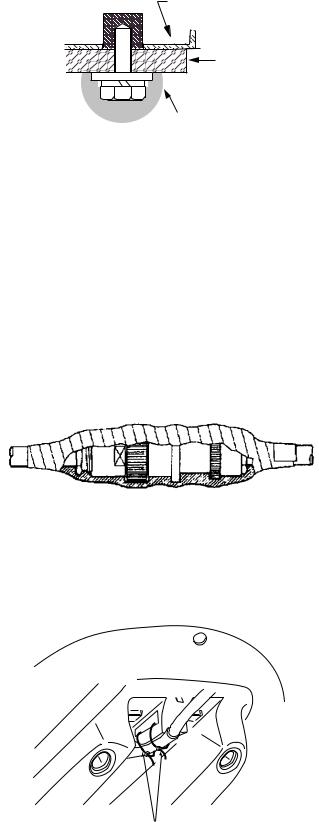
3. Coat exposed parts of nuts, bolts and washers with silicone sealant.
Radome base
Platform |
Coat with silicone sealant.
Coating bolt, nut and washers with silicone sealant
4.Connect the three coaxial cables coming from the antenna unit to the appropriate coaxial cables on the antenna cable, referring to the table below.
Cable from antenna |
Cable |
(no. marked on cable) |
TTPX6-3D2V-15M |
ANT 1 |
No color |
ANT 2 |
Yellow |
ANT 3 |
Red |
5.Cover the antenna connectors with vulcanizing tape and vinyl tape, for waterproofing. Tie tape ends with a cable tie.
Waterproofing the antenna connector
6.Set the joints of the coaxial cables into the cavity in the antenna base.
7.Pass two cable ties (long life, temperature resistant type, local supply) through the hole shown in the figure below. Fasten them at the locations shown in the figure below.
Cable Tie
How to fasten the antenna cable
2-5
2.INSTALLATION
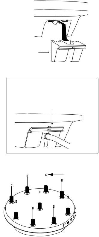
8.Set the “cable cover” to the antenna base as shown in the figure below.
Cable Cover
How to insert the cable cover
HOW TO REMOVE CABLE COVER
Insert slotted-head screwdriver here to remove cable cover.
9.If necessary, attach nine “bird-repellent fixtures” (supplied) to the antenna cover as shown below. Use the paper pattern to position the fixtures.
Bird-repellent fixture
 N
N
U
R
F |
U |
|
Antenna unit
2-6
2. INSTALLATION
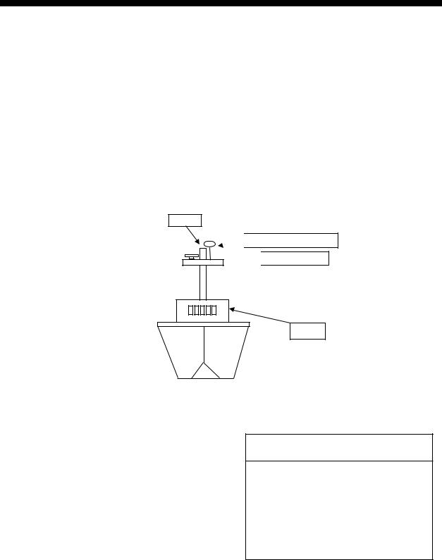
2.2.2DGPS antenna unit
Choose a mounting location for the DGPS antenna considering the points mentioned below. DPGS is not necessary for heading determination, however it can improve the accuracy of GPS position fixing
•Separate the DGPS antenna at least three meters from a radio antenna.
•Do not install the DGPS antenna within the radar beam.
1.Mount the DGPS antenna by one of the methods below.
•Screw it into a one-inch threaded pipe.
•Fasten it to a steel post (φ 35-φ 90) with stainless steel hose clamps (supplied).
 CAUTION
Ground the antenna to prevent receiving problems.
DGPS Antenna (preamp)
GR-800-SC-1-S
Whip Antenna
Spring Washer
50
Witt Threads (W25-14) Pitch: 1.8143 Qty: 14
Antenna cable
Hose
Clamp
Pipe f27.2
Ground to the ship’s body
as shown the right figure.
Post (f35-f90)
Ground Wire (0.3 m)
Note: Screw the pipe into the preamp BEFORE mounting the pipe.
Tap M4 threads in mast. Fasten ground wire with an M4 screw.
Mounting onto a threaded pipe |
Mounting with hose clamps |
Mounting the DGPS antenna
2.Set the spring washer to the whip antenna and screw the whip antenna into the antenna housing. Coat the washer with silicone sealant to prevent loosening.
3.Tap M4 threads on the post and fasten the ground wire with an M4 screw.
2-7
2.INSTALLATION
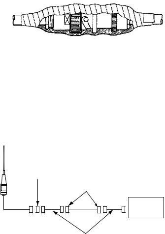
4.The DGPS antenna is supplied with a 15 m cable. If extension is necessary, use the extension cable (option). Cover the extension connector with vulcanizing tape and vinyl tape, for waterproofing. Tie tape ends with a cable tie.
Extension Cable: Type: OP08-15-30, Code No.: 004-396-440 (30 m) Type: OP08-15-60, Code No.: 004-396-450 (60 m)
Name |
Type |
|
|
Code No. |
Qty |
Remarks |
||
Connector |
TNC-SA-JJ |
|
000-139-113 |
1 |
|
|||
|
TNC-PS-3D |
L30M |
000-139-078 |
|
30 m, connector at |
|||
Cable |
|
|
|
|
|
1 |
both ends |
|
TNC-PS-3D |
L60M |
000-139-080 |
60 m, connector at |
|||||
|
|
|||||||
|
|
|
|
|
|
|
both ends |
|
|
|
|
|
|
|
|
|
|
|
|
|
|
|
|
|
|
|
Waterproofing the extension connector
For cable RG-10UY (local supply, max. length 60 m), use the optional antenna cable set.
Antenna cable set |
Type: OP08-17, Code No.: 004-392-510 |
|||
|
|
|
|
|
Name |
Type |
Code No. |
Qty |
Remarks |
Converter Cable Assy. |
NJ-TP-3DXV-1 |
000-123-809 |
2 |
|
Connector |
TNC-SA-JJ |
000-139-113 |
1 |
|
Connector |
N-P-7 |
000-501-514 |
2 |
|
|
*TNC-SA-JJ |
|
|
*N-P-7 |
|
|
|
Processor |
15 m |
RG-10UY |
Unit |
|
* Converter cable assy. (supplied with antenna cable set)
Cable connection when using cable RG-10UY
2-8
2. INSTALLATION
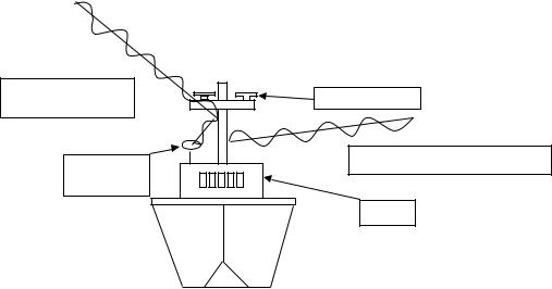
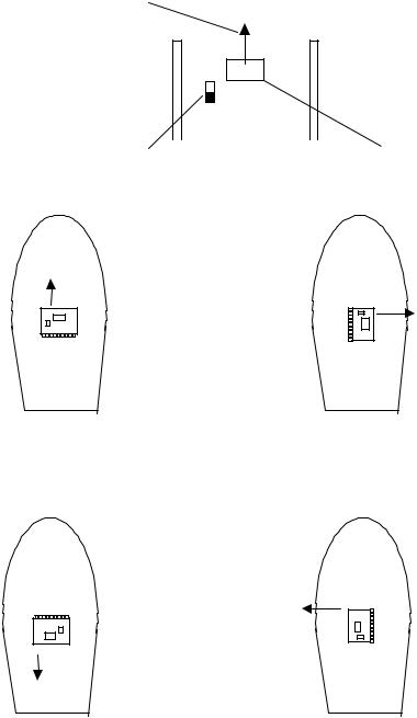
2.3Installing the Processor Unit
The processor unit should be mounted aligned with the ship’s fore-and-aft line. It can be mounted on the deck, bulkhead, or on the underside of a desk. Choose a mounting location which allows you to easily view the power lamp on the top of the unit and which is within ± 2.5° of the ship’s fore-and-aft line.
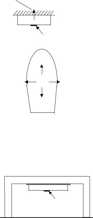
2.3.1Deck mount
1.The processor unit is factory adjusted for deck mounting. Fasten the processor unit to the mounting location with tapping screws (5 x 20, 4 pcs.). The unit can be oriented in one of the directions shown in the figure below. After the unit is installed, you will specify the mounting method from the menu.
Mount processor unit |
|
Reference Direction |
|
so reference |
|
|
|
direction is within |
|
|
|
±2.5° of |
|
|
POWER switch |
fore-and-aft line. |
|
|
|
Name plate |
|
|
(power lamp) |
|
|
|
|
|
Connectors |
|
|
|
Processor Unit, top view |
||
Bow |
|
|
Bow |
|
|
|
|
|
Mounting Method: "Floor" |
Mounting Method: "Floor" |
|
|
|
(Deck) |
(Deck) |
|
Mounting Direction: A |
Mounting Direction: B |
|
Port |
Starboard |
Port |
Starboard |
|
|||
|
DIRECTION "A" |
DIRECTION "B" |
|
Stern |
|
|
Stern |
Bow |
|
|
Bow |
|
Mounting Method: "Floor" |
Mounting Method: "Floor" |
|
|
|
(Deck) |
(Deck) |
|
Mounting Direction: C |
Mounting Direction: D |
|
Port |
Starboard |
Port |
Starboard |
DIRECTION "C" |
DIRECTION "D" |
Stern |
Stern |
|
Processor unit orientation, deck mounting
2.Fasten the ground wire between the ground terminal on the processor unit and the ship’s hull.
2-9
2. INSTALLATION
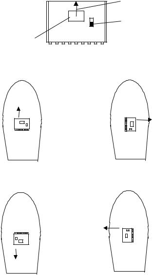
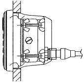
2.3.2Bulkhead mount
For mounting on a bulkhead, use the bulkhead mounting plate supplied with the installation materials.
1.Unfasten four screws from the top cover to open the front panel.
2.Unfasten two screws to dismount the angular rate sensor.
Angular Rate Sensor
BEACON
20P8171
Processor unit, top view
3.Fasten the bulkhead mounting plate to the angular rate sensor. Align the center graduation on the sensor with the hole of the bulkhead mounting plate and tighten fixing screws.
|
Hole of bulkhead |
Scale |
mounting plate |
|
|
Center Mark |
|
Angular Rate Sensor
Mounting Base
Fixing Screw
Angular rate sensor, top view
2-10

2. INSTALLATION
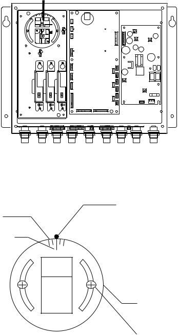
4.Loosen four screws on the angular rate sensor mounting base, and then fasten the bulkhead mounting plate to the angular rate sensor mounting base.
Angular Rate Sensor
Angular
Rate
Sensor
Mounting
Base
BEACON
20P8171
Bulkhead Mounting Plate
Top Fixing
Hole (x2)
 HEAD3 HEAD2 HEAD1
Processor unit, top view
5.Close the top cover of the processor unit.
6.Partially screw in two tapping screws for the top fixing holes of the processor unit in the mounting location. Hang the processor unit on the tapping screws, using the top fixing holes. Screw in two tapping screws for the bottom fixing holes, and then tighten the top fixing holes.
2-11
2. INSTALLATION
The unit can be oriented as shown in the figure below. After the unit is installed you will specify the mounting method from the menu.
Reference Direction
Bulkhead
Mount processor unit so reference direction is within
±2.5° of fore-and-aft line.
Name Plate (other side)
|
Direction |
|
Mounting Method: "Wall" |
|||||
|
A |
|
(Bulkhead) |
|||||
|
|
|
|
|
|
|
|
Mounting Direction: A |
|
|
|
|
|
|
|
||
Direction D |
|
|
|
|
|
|
|
Direction B |
|
|
|
|
|
|
|
||
|
|
|
|
|
|
|
||
|
|
|
|
|
|
|
||
Mounting Method: "Wall" |
|
|
|
|
|
|
|
Mounting Method: "Wall" |
|
|
|
|
|
|
|
||
(Bulkhead) |
|
|
|
|
|
|
|
(Bulkhead) |
|
|
|
|
|
|
|||
Mounting Direction: D |
Direction |
|
Mounting Direction: B |
|||||
|
C |
|
Mounting Method: "Wall" |
|||||
|
|
|
|
|
|
|
|
(Bulkhead) |
|
|
|
|
|
|
|
|
Mounting Direction: C |
Processor unit orientation, bulkhead mounting
7.Fasten the ground wire between the ground terminal on the processor unit and the ship’s superstructure.
2.3.3Installation on the underside of a desk
The processor unit may be mounted on the underside of a desk as shown in the figure below. Do not install it on the overhead.
Desk
Name Plate
Installation of processor unit on the underside of a desk
2-12
2. INSTALLATION
The reference direction is as shown below. The mounting method is the same as that for mounting on the deck.
Reference Direction
Mount processor unit so reference direction is within ±2.5° of fore-and-aft line.
POWER switch |
|
|
|
|
|
|
|
|
|
|
|
|
|
|
|
|
|
|
|
|
|
|
|
|
|
|
Connectors |
||||||||||||||||
(power lamp) |
|
|
|
|
|
||||||||||||||||
Processor Unit, rear view |
|||||||||||||||||||||
|
|||||||||||||||||||||
Bow |
|
|
|
|
|
|
|
|
|
|
|
|
|
|
|
|
|
|
|
Bow |
|
Mounting Method: Underside of
desk
Mounting Direction: A
Name plate (other side)
Mounting Method: Underside of desk Mounting Direction: B
Port |
Starboard |
Port |
Starboard |
DIRECTION "A" |
DIRECTION "B" |
Stern |
Stern |
|
Bow |
|
Bow |
Mounting Method: Underside of desk |
|
Mounting Method: Underside of desk |
|
||
|
Mounting Direction: C |
|
|
Mounting Direction: D |
Port |
Starboard |
Port |
|
Starboard |
DIRECTION "C" |
DIRECTION "D" |
Stern |
Stern |
Processor unit orientation, installation on the underside of a desk
Mount the processor unit on a level surface with its name plate facing the bow, stern, port or starboard.
2-13
2. INSTALLATION
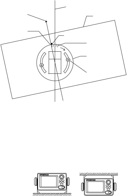
2.3.4Adjusting for orientation error
It may be impossible to perfectly align the processor unit on the fore-and-aft or port-and-starboard line. Open the top cover, loosen the two fixing screws on the angular rate sensor and turn. For example, if the orientation error is 2.5° to port, rotate the sensor 2.5° starboard. The range of adjustment is -45° to +45°. Close the top cover after completing the adjustment.
Bow-stern, Port-starboard direction
Reference |
Processor Unit |
|
Direction |
||
|
Scale
Hole on processor unit
Graduation, every 2.5°
Bulkhead Mounting
Plate
Fixing Screw
Angular rate sensor, top view
2.4Installing the Display Unit
2.4.1Desktop, overhead mounting
1.Fasten the hanger to the mounting location with four tapping screws (supplied). See the outline drawing for mounting dimensions.
2.Screw the knobs into the display unit.
3.Set display unit to the hanger and tighten the knobs.
4.Run the ground wire between the ground terminal on the display unit and the ship’s superstructure.
Desktop |
Overhead |
Display unit mounting methods
2-14
2. INSTALLATION
2.4.2Flush mount
Two types of flush mounts are available. See the outline drawing at the back of the manual for details.
Flush mount “F” |
|
|
|
|
|
Flush mount “F” kit |
Type: OP20-29, Code No: 000-041-405) |
||||
|
|
|
|
|
|
|
Name |
|
Type |
Code No. |
Qty |
|
Cosmetic Panel |
|
20-016-1051 |
100-251-370 |
1 |
|
Tapping Screw |
|
5X20 |
000-802-840 |
4 |
|
Hex Bolt |
|
M6X12 |
000-862-127 |
2 |
|
Spring Washer |
|
M6 |
000-864-260 |
2 |
1.Make a cutout in the mounting location. The dimensions are 183(W) x 92(H) mm.
2.Fasten the cosmetic panel to the display unit with hex bolts and flat washers.
3.Fasten the display unit to the mounting location with tapping screws.
Flush mount “S” |
|
|
|
|
Flush mount “S” kit |
Type: OP20-17, Code No.: 000-040-720) |
|||
|
|
|
|
|
Name |
|
Type |
Code No. |
Qty |
Flush Mount Fixture |
|
20-007-2401 |
100-183-190 |
2 |
Wing Bolt |
|
M4X30 |
000-804-799 |
4 |
Wing Nut |
|
M4 |
000-863-306 |
4 |
Hex Bolt |
|
M6X12 |
000-862-127 |
2 |
Spring Washer |
|
M6 |
000-864-260 |
2 |
1.Make a cutout in the mounting location. The dimensions are 167(W) x 92(H) mm.
2.Place the display unit in the cutout.
3.Fix the display unit to the two flush mount fixtures with hex bolts and spring washers.
4.Screw the butterfly nut on the butterfly bolt.
5.Fix the display unit with the butterfly bolt and then tighten the butterfly nut.
Flush mount “S”
2-15
2. INSTALLATION
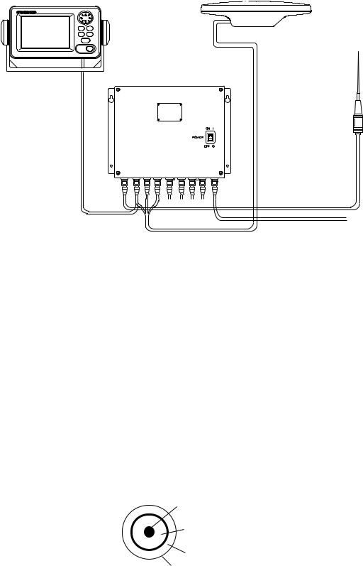
2.5Wiring
This section covers general wiring. For further details see the interconnection diagram at the back of this manual.
DISPLAY UNIT |
ANTENNA UNIT |
||||
SC-303 |
|||||
SC-602 |
|||||
|
|
|
|
||
|
|
|
|
|
|
|
* |
|
PROCESSOR UNIT |
|
SC-601/SC-601-D |
MJ-A7SPF0006-100, |
DGPS |
ANTENNA |
|
10m |
GR-800-1-S |
TNC-PS-3D (15 m)
12-24 VDC
MJ-A3SPF0013-035, TPPX6-3D2V-15M, 15m 3.5 m
General wiring diagram
•The display cable (display and processor units) is 10 m long. Connect it to the DISPLAY port on the processor unit.
•The antenna cable is 15 meters (standard length). Connect the three coaxial cables to the processor unit according to cable color as below. Incorrect connection will result in wrong heading.
Antenna |
TPPX6-3D2V-15M |
Port on |
|
Processor Unit |
|||
|
|
||
Antenna Element 1 |
No color |
GPS ANT 1 |
|
Antenna Element 2 |
Yellow |
GPS ANT 2 |
|
Antenna Element 3 |
Red |
GPS ANT 3 |
Note 1: Instead of TPPX6-3D2V, three Japan Industrial Standard coaxial cables 3D2V (local supply) or equivalent can be used as antenna cables.
3D2V |
50 W |
|
|
|
f5.3 mm |
|
Core |
|
f0.96 mm |
|
Insulator T1.02 mm |
Shield
Sheath
Sectional view of coaxial cable 3D2V
2-16
Loading...