


 Loading...
|
Installation Manual |
|
|
MULTI DISPLAY RD-30 |
|
SAFETY INSTRUCTIONS.................................................................... |
i |
|
SYSTEM CONFIGURATION ............................................................... |
ii |
|
EQUIPMENT LISTS ........................................................................... |
iii |
|
1. INSTALLATION ............................................................................... |
1 |
|
1.1 |
Installation of Display Unit........................................................................................ |
1 |
1.2 Wiring....................................................................................................................... |
3 |
|
2. INITIAL SETTINGS ......................................................................... |
7 |
|
2.1 |
Data Sentence Description ...................................................................................... |
7 |
2.2 |
IEC 61162-1 (NMEA 0183) Input Data Sentences ................................................... |
8 |
2.3 |
Setting Input/Output ................................................................................................. |
9 |
PACKING LIST................................................................................ |
A-1 |
|
OUTLINE DRAWINGS .................................................................... |
D-1 |
|
INTERCONNECTION DIAGRAM.................................................... |
S-1 |
|

9-52 Ashihara-cho,
Nishinomiya, Japan
Telephone : 0798-65-2111
Telefax : 0798-65-4200
All rights reserved. |
Printed in Japan |
PUB.No. IME-44130-E1
( YOSH ) RD-30
Your Local Agent/Dealer
FIRST EDITION : MAR. 2001 E1 : FEB. 03,2003
*00080917801*
*00080917801*
* 0 0 0 8 0 9 1 7 8 0 1 *
*IME44130E10*
*IME44130E10*
* I M E 4 4 1 3 0 E 1 *

 SAFETY INSTRUCTIONS
 WARNING
Do not open the cover unless totally familiar with electrical circuits and service manual.
Improper handling can result in electrical shock.
Turn off the power at the switchboard before beginning the installation.
Fire or electrical shock can result if the power is left on.
Be sure that the power supply is compatible with the voltage rating of the equipment.
Connection of an incorrect power supply can cause fire or equipment damage. The voltage rating of the equipment appears on the label above the power connector.
 CAUTION
Ground the equipment to prevent mutual interference.
Observe the following compass safe distances to prevent interference to a magnetic compass:
|
Standard |
|
Steering |
|
|
||
|
|
|
|
Display |
0.35 m |
|
0.25 m |
unit |
|
||
|
|
|
|
|
|
|
|
i

SYSTEM CONFIGURATION
FURUNO
MENU ENT
DISP DIM
*
RD-30 PWR
Multi display
RD-30
FURUNO
MENU ENT
DISP DIM
*
RD-30 PWR
Multi display
RD-30
FURUNO
MENU ENT
DISP DIM
*
RD-30 PWR
Multi display
RD-30
:Standard
:Option
GPS receiver
GP-310B
Sensor
GPS receiver
GP-310B
Sensor
Navigator
Ship's mains 12-24 VDC
ii

EQUIPMENT LIST
Standard supply
No. |
Name |
Type |
Code No. |
Qty |
Remarks |
|
|
|
|
|
|
1 |
Multi Display |
RD-30 |
- |
1 |
|
2 |
Spare Parts |
SP14-02901 |
- |
1 set |
|
3 |
Installation |
CP14-06000 |
- |
1 set |
+Tapping screw (4 pcs) |
|
Materials |
|
|
|
MJ-A7SPF0005-020 |
|
|
|
|
|
|
4 |
Accessories |
FP14-02801 |
- |
1 set |
Hard cover |
|
|
|
|
|
|
Optional supply
No. |
Name |
Type |
Code No. |
Qty |
Remarks |
|
|
|
|
|
|
1 |
Flush Mount Kit S |
OP20-17 |
000-040-720 |
1 |
For flush |
|
|
|
|
|
mounting the |
2 |
Flush Mount Kit F |
OP20-29 |
000-041-405 |
|
|
|
display unit |
||||
|
|
|
|
|
|
|
|
|
|
|
|
3 |
Cable Assy. |
MJ-A7SPF0005-020 |
000-139-384 |
1 |
Power, signal |
|
|
MJ-A7SPF0006-100 |
000-143-578 |
1 |
7P-7P |
|
|
|
|
|
cross cable |
|
|
MJ-A7SPF/SRMD-100 |
000-144-534 |
1 |
7P-7P |
|
|
|
|
|
straight cable |
|
|
|
|
|
|
Sensors available
No. |
Name |
Type |
Code No. |
Qty |
Remarks |
|
|
|
|
|
|
1 |
Smart Sensor |
235DT-MSE |
000-144-981 |
1 |
Depth & Temperature |
|
|
|
|
|
Sensor |
2 |
Smart Sensor |
235DT-PSE |
000-144-982 |
1 |
Depth & Temperature |
|
|
|
|
|
Sensor |
3 |
Smart Sensor |
235DST-PWE |
000-144-983 |
1 |
Depth, Speed and |
|
|
|
|
|
Temperature Sensor |
4 |
Smart Sensor |
235DHT-LMSE |
000-144-984 |
1 |
Depth and High Precision |
|
|
|
|
|
Temperature Sensor |
5 |
Smart Sensor |
235DHT-MSE |
000-144-985 |
1 |
Depth and High Precision |
|
|
|
|
|
Temperature Sensor |
For technical specifications see Airmar’s technical data.
iii
This page is intentionally left blank.
1.INSTALLATION
1.1Installation of Display Unit
Mounting considerations
The display unit can be installed on a tabletop, on the overhead, or in a panel (optional flush mounting kit required). Refer to the outline drawings at the end of this manual for installation instructions. When selecting a mounting location, keep in mind the following points:
•Locate the unit away from exhaust pipes and vents.
•The mounting location should be well ventilated.
•Mount the unit where shock and vibration are minimal.
•Locate the unit away from equipment which generates electromagnetic fields such as a motor or generator.
•Allow sufficient maintenance space at the sides and rear of the unit and leave sufficient slack in cables, to facilitate maintenance and servicing.
•Observe the following compass safe distances to prevent deviation of a magnetic compass.
Standard compass, 0.35 m, Steering compass, 0.25 m.
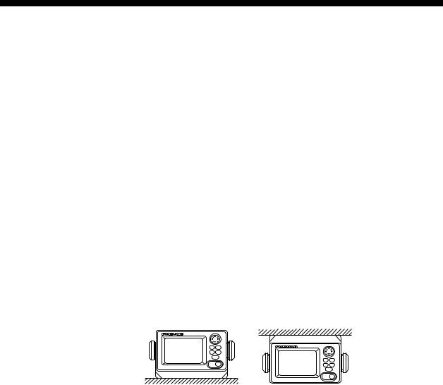
Tabletop and overhead mounting
Tabletop |
Overhead |
Figure 1-1 Tabletop and overhead mounting methods
1
Loading...