


 Loading...
VHF RADIOTELEPHONE
MODEL FM-8700
C
9 - 5 2 , A s h i h a r a - c h o , N i s h i n o m i y a , J a p a n
Telephone: |
0 7 9 8 |
- 6 5 |
- 2111 |
Telefax: |
0 7 9 8 |
- 6 5 |
- 4 2 0 0 |
A l l r i g h t s r e s e r v e d . Printed in Japan
|
P U B . No. O M E -561 70 |
(Y O S H) |
FM -8 7 0 0 |
 You r Loca l Agent/Dealer
FIRST E D I T I O N |
: |
A P R. |
199 8 |
K1 |
: |
JUL . 3 , |
2 0 0 2 |

CANCELING DISTRESS ALERT
If less than five seconds has elapsed since the [DISTRESS] key was pressed, the distress alert may be canceled by pressing the [ALARM STOP] key. Otherwise, do the following:
1.Switch off equipment immediately.
2.Switch equipment on and set to Channel 16.
3.Transmit message to "All Stations” giving your vessel's name, callsign and DSC number to cancel the distress alert.
Example message:
All Stations, All Stations, All Stations
This is VESSEL'S NAME, CALLSIGN,
DSC NUMBER, POSITION.
Cancel my distress alert of DATE, TIME, UTC.
=Master, VESSEL'S NAME, CALLSIGN. DSC NUMBER, DATE, TIME UTC.
i

 SAFETY INSTRUCTIONS
 WARNING
Do not open the equipment.
Hazardous voltage which can cause electrical shock, burn or serious injury exists inside the equipment. Only qualified personnel should work inside the equipment.
Do not disassemble or modify the equipment.
Fire, electrical shock or serious injury can result.
Turn off the power immediately if water leaks into the equipment or the equipment is emitting smoke or fire.
Continued use of the equipment can cause fire or electrical shock.
Do not place liquid-filled containers on the top of the equipment.
Fire or electrical shock can result if a liquid spills into the equipment.
Do not operate the equipment with wet hands.
Electrical shock can result.
Keep heater away from equipment.
Heat can alter equipment shape and melt the power cord, which can cause fire or electrical shock.
Any repair work must be done by a licensed radio technician.
Improper repair work can cause electrical shock or fire.
 CAUTION
Do not touch any part of the antenna when the equipment is transmitting.
Electrical shock can result.
Use the proper fuse.
Use of a wrong fuse can result in fire or permanent equipment damage.
Do not use the equipment for other than its intended purpose.
Personal injury can result if the equipment is used as a chair or stepping stool, for example.
Do not place objects on the top of the equipment.
The equipment can overheat or personal injury can result if the object falls.
ii

TABLE OF CONTENTS
FOREWORD ..................................................................................................................... |
v |
SYSTEM CONFIGURATION .................................................................................. |
vii |
1. VHF RADIOTELEPHONE OPERATIONAL OVERVIEW
1.1 |
Front Panel ................................................................................................................. |
1-1 |
1.2 |
VHF Controls, Indications ......................................................................................... |
1-2 |
1.3 |
Turning the Power On/Off .......................................................................................... |
1-2 |
1.4 |
Selecting Channel Modes, Channels .......................................................................... |
1-3 |
1.5 Adjusting Volume of Loudspeaker ............................................................................. |
1-3 |
|
1.6 Adjusting Squelch, Selecting Operating Functions .................................................... |
1-3 |
|
1.7 |
Transmitting ............................................................................................................... |
1-4 |
1.8 |
Selecting Output Power .............................................................................................. |
1-4 |
1.9 |
Turning the Loudspeaker On/Off ............................................................................... |
1-4 |
1.10 Automatic Selection of CH16 .................................................................................. |
1-4 |
|
1.11 Dual Watch ............................................................................................................... |
1-5 |
|
1.12 Scanning ................................................................................................................... |
1-5 |
|
1.13 Remarks on Voice Communications ........................................................................ |
1-6 |
|
2. DSC TERMINAL OPERATIONAL OVERVIEW
2.1 |
DSC Controls, LED Warnings ................................................................................... |
2-1 |
2.2 |
DSC Operational Overview ....................................................................................... |
2-4 |
2.3 Turning Remote & Auto Acknowledge On/Off ......................................................... |
2-7 |
|
3. DSC DISTRESS COMMUNICATIONS
3.1 |
Distress Alert Transmission ........................................................................................ |
3-1 |
3.2 |
Manual Entry of Own Ship’s Position and Time ........................................................ |
3-3 |
3.3 |
Canceling a Distress Call ........................................................................................... |
3-4 |
3.4 |
Receiving Distress Alert from Other Vessel, Transmitting DIST ACK Signal .......... |
3-5 |
3.5 |
Distress Alert Relay .................................................................................................... |
3-9 |
4. DSC OPERATION FOR NON-DISTRESS CASES
4.1 |
Transmitting Individual Calls ..................................................................................... |
4-1 |
4.2 |
Receiving Individual Calls (ACK RQ) ...................................................................... |
4-5 |
4.3 |
Transmitting All Ships Calls ...................................................................................... |
4-9 |
4.4 |
Receiving All Ships Calls ......................................................................................... |
4-12 |
iii
4.5 |
Preparing and Saving Messages ............................................................................... |
4-16 |
4.6 |
Writing Over Files .................................................................................................... |
4-18 |
4.7 |
Opening, Transmitting Files ..................................................................................... |
4-19 |
4.8 |
Transmit/Receive Message Memory ........................................................................ |
4-20 |
5. OTHER CALLING TYPES
5.1 |
Selection of Other Calling Types ............................................................................... |
5-1 |
5.2 |
Making Telephone Calls ............................................................................................. |
5-3 |
5.3 |
Receiving Telephone Call from Coast Station ........................................................... |
5-6 |
5.4 |
Other Station IDs and Telephone Numbers ................................................................ |
5-7 |
6. USER PREFERENCES
6.1 Automatic or Manual Printing (Printer setup) ............................................................ |
6-1 |
6.2 Turning Key Beep On/Off .......................................................................................... |
6-4 |
6.3 Alarm Setup ................................................................................................................ |
6-5 |
7. SYSTEM CONFIRMATION
7.1 |
Confirming Own Ship’s ID ........................................................................................ |
7-1 |
7.2 |
Confirming ROM Version No. ................................................................................... |
7-2 |
7.3 |
Confirming VHF Section Settings ............................................................................. |
7-3 |
7.4 |
Confirming VHF Channels ........................................................................................ |
7-4 |
7.5 |
Confirming Tx Output Power .................................................................................... |
7-5 |
8. MAINTENANCE & TROUBLESHOOTING
8.1 Maintenance ............................................................................................................... |
8-1 |
8.2 Troubleshooting .......................................................................................................... |
8-1 |
8.3 Diagnostic Test ........................................................................................................... |
8-2 |
SPECIFICATIONS..................................................................................................... |
SP-1 |
APPENDIX ...................................................................................................................... |
A-1 |
Menu Tree ....................................................................................................................... |
A-1 |
Marine VHF Channel Lists ............................................................................................. |
A-4 |
Digital Interface (IEC 61162-1 Edition 2)....................................................................... |
A-9 |
INDEX......................................................................................................................... |
Index-1 |
Declaration of conformity to type |
|
iv

FOREWORD
A Word to FM-8700 Owners
Congratulations on your choice of the FURUNO FM-8700 VHF Radiotelephone. We are confident you will see why the FURUNO name has become synonymous with quality and reliability.
For over 40 years FURUNO Electric Company has enjoyed an enviable reputation for quality marine electronics equipment. This dedication to excellence is furthered by our extensive global network of agents and dealers.
This equipment is designed and constructed to meet the rigorous demands of the marine environment. However, no machine can perform its intended function unless operated and maintained properly. Please carefully read and follow the recommended procedures for operation and maintenance.
We would appreciate hearing from you, the end-user, about whether we are achieving our purposes.
Thank you for considering and purchasing FURUNO equipment.
v
Features
The FURUNO FM-8700 is a cost-effective all-in-one marine VHF radio system consisting of a 25 W VHF radiotelephone, a DSC modem, a CH 70 watch receiver, and a duplexer unit. It complies with GMDSS carriage requirements for safety and general communications.
The FM-8700 offers simplex/ full-duplex voice communications on ITU channels in the marine mobile VHF band. The features include Dual Watch which allows a continuous watch on CH16 and another selected frequency.
Full Class-A DSC functions are provided for distress alert transmission and reception, as well as the general call formats (Individual telephone, All Ships, Group and Area Call). Distress alert can be readily transmitted but an arrangement is provided to prevent accidental activation. The FM-8700 maintains a continuous watch on CH70 even while another VHF channel is in use. Aural and visual alarms are given to incoming DSC messages.
The main features of the FM-8700 are
•Compact cabinet allows for flexible and space-saving installation on a navigation console or at the conning position
•Conforms to the following standards and regulations:
IMO A. 694(17)
IMO A. 803(19)
IMO A. 524(13)
IMO MSC 68(68), MSC/Circ.862
IEC-61097-3/7/8
IEC-60945 (3rd edition)
IEC-61162-1
ETS 300 338, 301 033, 300 162
ITU-R M.493-9, M.541-8, M.689-2
•Full-duplex communications
•Precision PLL frequency synthesizer for high frequency stability as required for DSC operation
•Dual Watch and Multiple Watch
•Continuous DSC watch on CH70
•Prevention of accidental distress alert
•File editing for emergency readiness
•Automatic entry of own ship position with manual override
Program number
DSC |
0550192004 (version 1.06) |
RT |
0550193004 (version 1.04) |
vi

SYSTEM CONFIGURATION
The FM-8700 is a highly advanced, full-duplex, fully synthesized 25 W VHF transceiver with DSC terminal. It is designed to satisfy the stringent requirements of marine communications, and complies with GMDSS carriage requirements for safety and general communications.
VHF |
CH70 RX |
Antenna |
Antenna |
|
|
|
|
DX-8700 |
|
Navigation Device |
||||
|
|
|
|
|
|
|
||||
|
|
|
|
|
|
|
|
|
Wing Handset (port) |
|
|
|
|
|
DUPLEXER UNIT |
|
|
|
|||
|
|
|
|
|
Wing Handset (starboard) |
|||||
|
|
|
|
|
|
|
|
|
||
|
|
|
|
|
|
|
|
|||
|
|
|
|
|
|
|
|
AC/DC |
110/220 VAC |
|
|
|
|
|
|
|
|
|
|||
|
|
|
|
|
|
|
|
Power |
|
|
|
|
|
|
|
|
|
|
Supply |
24 VDC |
|
|
|
|
|
|
|
|
|
Unit PR-300 |
||
|
|
|
|
|
|
|
|
|
||
|
Handset |
|
TRANSCEIVER UNIT |
24 VDC |
|
|||||
|
|
|
||||||||
|
|
|
|
|||||||
|
|
|
|
|||||||
|
|
|
|
|
|
|||||
External Speaker |
|
|
|
|
|
|
|
|
||
|
|
|
|
FM-8700 |
Distress |
|
||||
|
|
|
|
|
|
|
|
Message |
|
|
|
|
|
|
|
|
|
|
Controller |
|
|
Remote Station RB-700 |
|
|
|
|
|
DMC-5 |
|
|||
|
|
|
|
|
|
|
|
|||
|
|
|
|
|
|
|
|
Printer |
Printer |
|
Distributor DB-500 |
|
|
|
|
|
Interface |
||||
|
|
|
|
|
PP-510 |
|||||
|
|
|
|
|
IF-8500 |
|||||
|
|
|
|
|
|
|
|
|
||
|
|
|
|
|
|
|
|
|
|
|
:Standard Supply
:Optional Supply
Figure 1 FM-8700 system configuration
vii
This page is intentionally left blank.
1.VHF RADIOTELEPHONE OPERATIONAL OVERVIEW
The FM-8700 system consists of a transceiver unit, a duplexer unit and two antennas. The transceiver unit contains a VHF transmitter, receiver, and channel 70 watch receiver module. All operations are controlled on its front panel.
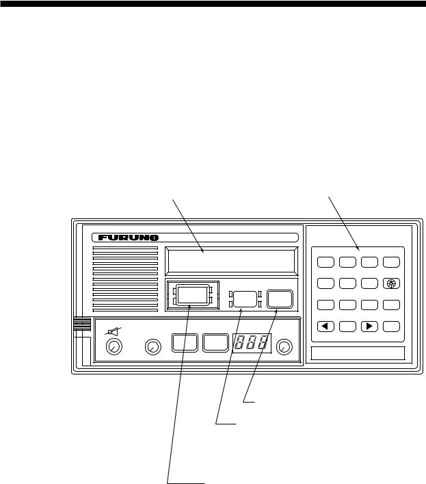
1.1 Front Panel
|
|
|
Keyboard |
|
||
Controls for |
LCD |
|
(for DSC operation) |
|||
DSC calling |
|
|
|
|
|
|
VHF RADIOTELEPHONE FM-8700 |
|
|
|
|
||
Watch CH 70 |
|
|
POSITION |
AUTO ACK |
TEST |
|
|
|
1 |
2 |
3 |
CANCEL |
|
auto |
|
|
||||
|
|
|
|
|
|
|
|
|
|
CONTRAST |
VOLUME |
|
|
|
DISTRESS CANCEL |
|
4 |
5 |
6 |
|
DISTRESS |
ALARM |
CALL |
FILE |
RCVD |
XMTD |
|
|
STOP |
7 |
8 |
9 |
SELECT |
|
|
|
|||||
|
|
|
||||
Controls for VHF operation
VOLUME |
SQUELCH |
|
|
|
|
|
CHANNEL |
0 |
ENT |
|
OFF/DW/SCAN(PUSH) |
LOW |
TX |
REM |
USA |
WX |
PRIV MODE(PUSH) |
||
|
|
|
|||||||
|
(PUSH) |
|
|
|
|
|
|
|
|
|
|
HI |
CH16 |
|
|
|
|
|
|
|
|
LOW |
|
|
|
|
|
|
|
|
|
|
|
|
|
|
|
|
|
OFF |
AUTO |
|
|
|
|
|
|
|
|
Volume with |
CH16 key |
Channel selector |
|
High/Low power |
|||
Power ON/OFF |
(Press for Mode selection.) |
||
|
|||
(Press to turn |
Squelch control |
Channel No. display |
|
loudspeaker on/off.) |
(Press for DW, Scan.) |
|
Figure 1-1 FM-8700 transceiver unit
1-1

1.2 VHF Controls, Indications
Control |
Function |
CHANNEL/ |
CHANNEL (Rotary control): Selects a |
MODE |
channel. |
|
MODE (Push): Changes modes in order of |
|
INTL, USA, WX and PRIV. (USA, WX and |
|
PRIV modes available where permitted.) |
|
|
SQUELCH/ |
SQUELCH (Rotary control): Mutes the |
DW/SCAN |
receiver when no signal is present on the |
|
channel selected. AUTO position |
|
automatically reduces white noise. |
|
DW/SCAN (Push): Changes the operating |
|
function in order of Dual Watch, Scan and |
|
Off. |
|
|
VOLUME |
Rotation turns the power on/off and adjusts |
|
the volume of the loudspeaker. Pressing turns |
|
off the internal loudspeaker. |
|
|
HI/LOW key |
Alternates high and low output power. |
|
|
CH16 key |
Selects channel 16. |
Indication |
Meaning |
|
Internal loudspeaker OFF by pressing the |
|
VOLUME control. Internal loudspeaker is |
|
automatically turned off whenever the handset |
|
is set in its rest. |
|
|
LOW |
Lights RF power is LOW. |
|
|
TX |
Lights while transmitting. |
|
|
REM |
Lights when FM-8700 is being controlled by |
|
Remote Station RB-700. |
|
|
USA |
USA mode. (Some ITU duplex channels are |
|
used as simplex channels.) |
|
|
WX |
Lights when a weather channel is selected. |
|
(Available in USA version.) |
|
|
DW/SCAN |
DW for Dual Watch; SCAN for scanning. |
1.3 Turning the Power On/Off
To turn the power on, turn the VOLUME control clockwise until you hear a click. To turn the power off, turn the control fully counterclockwise until you hear the click.
1-2

1.4 Selecting Channel Modes, Channels
Selecting channel modes
While pressing the CHANNEL selector, press the CH16 key to select the channel mode: International, USA (in the case of USA channel permitted), private (if authorized), or weather mode (USA channel permitted). The International version of the FM-8700 has no such selection.
On the weather channel mode, a beep is emitted when the weather alert tone is received.
Note: Private channels are available only where permitted by the authorities.
Selecting channels
Rotate the CHANNEL selector clockwise (counterclockwise) to display desired channel in the channel No. display window.
1.5 Adjusting Volume of Loudspeaker
The VOLUME control adjusts the volume of the loudspeaker.
1.6 Adjusting Squelch, Selecting Operating Functions
Adjusting squelch
The SQUELCH control adjusts the squelch threshold level. Adjust it so that white noise heard in the loudspeaker just fades out. Perform this operation when no traffic is being received. AUTO squelch automatically reduces white noise. Usually select the AUTO position. Avoid turning the squelch too far clockwise – you may miss a long distance communication.
Note: To obtain correct scan watch/dual watch response, adjust the SQUELCH control precisely.
Selecting operating function
Every pressing of the SQUELCH control changes the operating function as follows:
OFF |
DW |
SCAN |
1-3
1.7 Transmitting
Press the PTT (Press-to-talk) switch on the handset or microphone to talk, and release it to listen for the response. The VHF section keyboard accepts no key input when the PTT switch is operated.
Remarks on transmitting
•Before transmitting, think about the subjects which have to be communicated and, if necessary, prepare written notes to avoid unnecessary interruptions and ensure that no valuable time is wasted on a busy channel.
•Listen before commencing to transmit to make certain that the channel is not already in use.
1.8Selecting Output Power
Each press of the [HI/LOW] key selects HI or LOW output power. LOW appears when low power is selected. The transmitter power is automatically set for low on the following channels:
International: |
CH15, CH17 |
USA: |
CH13, CH15, CH17, CH67; to operate USA chan- |
|
nel 13 or 67 in high power, keep [HI/LOW] pressed |
|
while talking into the handset. |
1.9 Turning the Loudspeaker On/Off
To turn the loudspeaker on/off, press the VOLUME control. The loudspeaker off mark appears when the speaker is off. The loudspeaker is automatically turned off when the telephone handset is used on semi-duplex channels.
1.10 Automatic Selection of CH16
Press the [CH16] key to select CH16, the International Calling and Safety Channel. The use is limited to distress, safety and calling. The transmission on CH16 (156.800 MHz) should be limited to within 1 minute except for distress calling.
Avoid calling on CH16 for purposes other than distress, urgency and very brief safety communications when another calling channel is available.
1-4

1.11 Dual Watch
The dual watch function permits watch on CH16 and another selected channel. CH16 and another channel are watched at intervals of 0.15 seconds and one second, respectively.
To start DW, first select the other frequency to watch and then press the SQUELCH control. When the receiver finds a signal on CH16, it locks on it and restarts dual watching after the signal on CH16 has gone. If another channel has traffic, it still continues dual watch. The speech is heard intermittently. If you are annoyed with the intermittence, turn off DW by pressing the PTT switch on the handset or pressing the SQUELCH control.
1.12 Scanning
The receiver scans all channels in the selected channel mode in ascending channel order, watching CH16 between channels as below:
1  16
16  2
2  16
16  3
3  16
16  4…
4…
16  88
88  16
16  87
87  16
16  86
86  16…
16…
To start scanning, press the SQUELCH control. When the receiver finds a signal, scanning is stopped on that channel and starts dual watch on it and CH16.
1-5

1.13 Remarks on Voice Communications
Automatic acknowledge (DSC operation) is automatically changed to manual acknowledge when voice communications begin. (The “auto” indication, however, remains on the screen.) This is done to prevent break in communications. Automatic acknowledge is automatically restored once voice communications are terminated.
Priority
The priority of the equipment is as follows: DSC section of FM8700>Wing handset>Handset of FM-8700>Remote Station RB700
Note: Time-out Timer
The FM-8700 is equipped with an automatic timing device that deactivates the transmitter and reverts the transceiver to the receive mode after an uninterrupted transmission period of 5 minutes. Please contact your dealer if necessary.
1-6
2.DSC TERMINAL OPERATIONAL OVERVIEW
Digital Selective Calling (DSC) is the globally adapted system by the ITU-R and IMO for selective calling of coast station and ship radio stations. The DSC system is used for both safety and routine. The GMDSS requires the use of DSC for distress alerting and safety calls.
2.1 DSC Controls, LED Warnings
DSC controls
LCD |
DSC controls |
VHF RADIOTELEPHONE FM-8700
|
Watch VHF ch70 |
|
POSITION |
AUTO ACK |
TEST |
|
||
|
|
1 |
2 |
3 |
CANCEL |
|||
|
auto |
|
|
|
||||
|
|
|
|
|
|
|
|
|
|
|
|
|
|
CONTRAST |
VOLUME |
|
|
|
|
|
DISTRESS CANCEL |
|
4 |
5 |
6 |
|
|
DISTRESS |
|
ALARM |
CALL |
FILE |
RCVD |
XMTD |
|
|
|
|
STOP |
7 |
8 |
9 |
SELECT |
|
|
|
|
|
|||||
|
|
|
|
|
||||
VOLUME |
SQUELCH |
|
|
CHANNEL |
|
0 |
|
ENT |
(PUSH) OFF/DW/SCAN(PUSH) LOW |
TX |
REM USA WX PRIV |
|
|
||||
MODE(PUSH) |
|
|
|
|
||||
|
HI |
CH16 |
|
|
|
|
|
|
|
LOW |
|
|
|
|
|
|
|
|
|
|
|
|
|
|
|
|
OFF |
AUTO |
|
|
|
|
|
|
|
Transmits messages other than distress.
Silences the receive alarm.
Stops repetitive alerts.
Transmits the distress alert. Press the [DISTRESS] key 4 seconds continuously.
Figure 2-1 FM-8700 transceiver unit
2-1

DISTRESS
ALARM
STOP
LED warnings
The four LEDs surrounding the [DISTRESS] key light continuously when the distress signal is transmitted.
•The upper two of the four LEDs surrounding the [ALARM STOP] key blink (and alarm sounds) when distress or urgent message is received. LEDs can be extinguished and alarm silenced by pressing the [ALARM STOP] key.
•The lower two LEDs (Green) blink (and alarm sounds) when message other than distress/urgent are received. Alarm is automatically silenced five seconds after message is received.
2-2

DSC control description
|
|
POSITION AUTO ACK |
TEST |
|
|
|
|
1 |
2 |
3 |
CANCEL |
|
|
CONTRAST |
VOLUME |
|
|
|
|
4 |
5 |
6 |
Figure 2-2 DSC keyboard |
|
|
FILE |
RCVD |
XMTD |
|
|
|
|
|||
|
|
7 |
8 |
9 |
SELECT |
|
|
|
0 |
|
ENT |
Key |
|
|
Function/Purpose |
||
0 |
9 |
Enter numeric data. |
|
|
|
CANCEL |
Cancels wrong data and restores previous menu. |
||||
|
|
Adjusts illumination of LED and keys in four levels. |
|||
SELECT |
1. Displays Set up menu (Main menu). |
||||
|
|
2. Changes settings of items appearing with blinking question mark. |
|||
ENT |
|
Registers key input. (Blinking item is registered when key is pressed.) |
|||
|
|
1. Shifts the cursor leftward. |
|
|
|
|
|
2. Restores previous display when pressed at displays with a blinking |
|||
|
|
question mark. |
|
|
|
|
|
Shifts the cursor rightward. |
|
|
|
POSITION |
|
Position and time are shown while pressed and held down. |
|||
1 |
|
||||
|
|
|
|
|
|
AUTO ACK |
|
Turns automatic transmission of acknowledge call (AUTO ACK) on/off. (Refer |
|||
2to page 2-8.) Note that distress alert cannot be automatically acknowledged by "auto acknowledge."
TEST
3 |
Conducts self-tests. |
|
4 |
Printing. (Also sets up automatic printing.) |
|
|
||
|
|
|
CONTRAST |
Adjusts contrast of LCD in eight levels. |
|
5 |
||
|
||
|
|
|
FILE |
Opens files. |
|
7 |
||
|
||
|
|
|
RCVD |
Displays contents of received messages. (Storage capacity: 100 files, 50 |
|
|
||
8 |
each of distress and other.) (Refer to page 4-20.) |
|
|
|
|
XMTD |
Displays contents of transmitted messages. (Storage capacity: 50 files.) |
|
9 |
||
(Refer to page 4-20.) |
||
VOLUME |
Not used. |
|
6 |
|
2-3
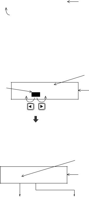
2.2 DSC Operational Overview
Standby display
When the FM-8700 is turned on, the following display appears. This display is known as the “standby display.” This is where you will begin most operations.
Watch VHF CH70 |
|
Standby display |
auto |
|
screen |
|
|
|
|
|
|
[2] key pressed to get "auto" screen. |
|
|
Should you get lost in operation you can return to the standby display by pressing the [CANCEL] key several times.
Selecting and registering items
The arrow keys ([t] and [s]) function to select items on the LCD.
After selecting item, press the [ENT] key to register it.
|
|
|
Item selected by cursor |
|
|
|
|
appears here. |
|
Blinking |
Call type <ALL ships> |
Call type |
||
cursor |
|
|
||
IND TEL ALL R/A --- |
selection screen |
|||
encloses |
||||
|
||||
|
|
|
||
current |
|
|
|
|
selection. |
(Scrolls |
(Scrolls |
|
|
|
screen |
screen |
|
|
|
leftward.) |
rightward.) |
|
|
Press the [ENT] key.
When blinking question mark appears
Press the [ENT] or [SELECT] key depending on your desire.
* VHF call message *
Format  INDIVIDUAL
Blinking question mark
Format selection screen (In this example it is format for "VHF call message.")
If change is necessary |
If no change is necessary, |
press the [SELECT] key. |
press the [ENT] key. |
2-4
Preparing and transmitting DSC messages
There are two methods by which you can prepare and transmit DSC messages, and they are shown below.
Preparing message for immediate transmission
Prepare message and then transmit it as follows:
Standby display
Press the [ENT] key.
* VHF call message *
Format INDIVIDUAL
For how to prepare a DSC message, refer to page 4-1.
After preparation, press the [CALL] key to transmit the DSC message.
Transmitting a message stored in the memory
99 messages (excluding distress message) can be saved to the memory. You may open a memory-stored message and transmit it as follows:
Standby display
Press the [SELECT] key.
Set up menu < |
|
|
> |
|
|||
1 |
2 |
3 |
4 |
6 |
7 |
9 |
ALM |
|
|
|
|
|
|
|
|
|
|
|
|
|
|
|
|
Press the [7] key.
For how to prepare and store a message, refer to "4.5 Preparing and Saving Messages."
After the standby display appears, press keys in the order shown below to transmit a DSC messages.
Press the [7] key. / (Enter file number.) / Press the [CALL] key.
2-5
Distress alert transmission and output power
When the distress alert is transmitted (by pressing the [DISTRESS] key), the output power of the FM-8700 is automatically set to maximum (25 W).
When keyboard input is prohibited
The DSC section keyboard accepts no key input while a DSC message is being transmitted. (DSC keyboard is inoperative about 3 seconds during a DSC distress call; 0.5 seconds for other DSC calls.)
2-6

2.3 Turning Remote & Auto Acknowledge On/Off
To enable or disable AUTO ACK and remote control, press the [2} key. Each press of the key enables or disables automatic acknowledge and remote control function in the sequence shown below.
Watch
Auto
Press [2] key
Watch
Manual
Press [2] key
Watch
Limit
Press [2] key
Automatic |
Remote control function |
||
|
|
||
At transmission |
|
||
acknowledge |
|
||
with [CALL] key |
At reception |
||
|
|||
|
pressed |
|
|
|
|
|
|
ON |
ON |
ON |
|
|
|
|
|
ON |
ON |
OFF |
|
|
|
|
|
|
|
1) When receiving |
|
|
|
all ships call or |
|
|
|
call related to |
|
OFF |
ON |
distress: ON |
|
2) When receiving |
|||
|
|
||
|
|
calls other than |
|
|
|
the above: OFF |
|
|
|
|
|
Limit acknowledge
The limit setting provides restricted use of the remote control function. It is useful when the following is desired:
•Automatically set a working channel when receiving anAll Ships call so as not to miss initial voice from the transmitting station.
•Prevent automatic transmission of acknowledge back (ACK BQ) in response to an individual call, when no operator is present.
•Prevent automatic transmission of own ship position data in response to an individual call which requests such data.
Auto acknowledge is automatically disabled when…
•An Error Checking Code (ECC) appears at the end of a receive message.
•A distress alert is received. (A distress alert cannot be acknowledged automatically.)
•Conducting voice communications.
2-7
This page is intentionally left blank.

3. DSC DISTRESS COMMUNICATIONS
3.1 Distress Alert Transmission
1


 2
2 


3-1
(from previous page)
* Received * DISTRESS ACK
ID : 001234567
ID of station (usually coast station) which transmitted DIST ACK.
Commence voice communications with coast station on CH16.
1. Provide the following information to the coast station:
Distress call
(1)Speak slowly and distinctly, “MAYDAY, MAYDAY, MAYDAY,” pronounced as the French expression “m’aider.”
(2)This is;
(3)The name of your vessel and call sign three times.
Then, begin the distress communications, which consists of:
Distress communications
(1)Position in latitude and longitude;
(2)The name of the distress;
(3)The kind of assistance desired;
(4)Any other information which might facilitate rescue, for example, length, color, and type of vessel, number of persons on board.
2.Indicate the end of message by saying “Over.”
Some countries do not have sea area A. In this case “ACK” from the coast station does not arrive over DSC. A ship nearby will contact the vessel in distress over CH16. After transmitting the distress alert, conduct voice distress communications as shown above.
3-2

3.2 Manual Entry of Ship’s Position and Time
Entering data manually
If automatic position input is lost for one minute the message "EPFS error" appears. In this case, enter position manually as below.
(Normal display)
* VHF call message * |
Watch VHF CH70 |
Format: DISTRESS
To enter data manually from the Distress Alert message, press [ENT]
and select call type
Distress. Press the [SELECT] key followed by the [1] key.
Press [ENT], [ENT] [SELECT] in this order.
Position |
< |
|
> |
|
|
|
|
NORTH= |
° |
S |
E= |
° |
W |
UTC= |
: |
Enter |
|
|
Enter |
|
|
Enter time |
|
latitude. |
|
|
longitude. |
|
|
(UTC). |
|
To move blinking cursor from NORTH |
Press the [ENT] key. |
|
(Returns to normal |
||
position to SOUTH, press the [s] key. |
||
display.) |
||
|
Note: If the manually entered position is not updated within four hours the buzzer sounds and the message "Warning: Update position!" appears on the screen. And if not updated within 23.5 hours the position entered is erased. Once automatic input of position is restored, cancel manually entered position as below.
Confirming Ship's Position and Time
Press and hold down the [1] (POSITION) key, ship's position and time are shown while the key is pressed.
Canceling manually entered data
To cancel the manually entered data, enter 9999 for the time and press the [ENT] key.
Note: Above procedure may also be used when you do not know your ship's position. This data is input as NO INFORMATION in POS&TIME in the DISTRESS ALERT MESSAGE.
3-3
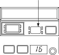
3.3 Canceling a Distress Call
Within five seconds after pressing the [DISTRESS] key
If the [DISTRESS] key is pressed by mistake, press the [ALARM STOP] key immediately (within 5 seconds). The distress call will be canceled.
[ALARM STOP] key
* Ready for calling * |
||||
DISTRESS CALL |
CH70 |
|||
|
|
DISTRESS CANCEL |
|
|
DISTRESS |
|
ALARM |
CALL |
|
|
|
STOP |
|
|
|
|
|
|
|
LOW |
TX |
REM USA |
WX PRIV |
CHANNEL |
MODE(PUSH) |
||||
HI |
CH16 |
|
LOW |
||
|
Figure 3-1 ALARM STOP key
If more than five seconds elapses after the [DISTRESS] key is pressed
1.Switch off equipment immediately.
2.Switch equipment on and set to Channel 16.
3.Transmit message to “All Stations” giving your vessel's name, callsign and DSC number to cancel the distress alert.
Example message
All Stations, All Stations, All Stations
This is VESSEL'S NAME, CALLSIGN,
DSC NUMBER, POSITION.
Cancel my distress alert of DATE, TIME, UTC.
=Master, VESSEL'S NAME, CALLSIGN. DSC NUMBER, DATE, TIME UTC.
3-4

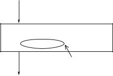
3.4Receiving Distress Alert from Other Vessel, Transmitting DIST ACK Signal
In no case is a ship permitted to transmit a DSC distress relay call on receipt of a DSC distress alert on VHF channel 70.
Procedure when in area A1
1.When the FM-8700 receives a distress alert from another vessel the upper two LEDs (Red) near the [ALARM STOP] key blink and the FM-85700 sounds the distress alarm.
2.Silence the alarm by pressing the [ALARM STOP] key.
3.Wait up to three minutes until the DIST ACK signal from a coast station is received. Be prepared to follow the instructions of the coast station.
4.If you do not receive the DIST ACK signal, follow the flow chart shown on the next page.
If further DSC alerts are received from the same source and the ship in distress is beyond doubt in the vicinity, a DSC acknowledgement may, after consulation with an RCC or Coast Station, be sent to terminate the call.
Note 1: An asterisk (*) in a received distress alert message indicates error or unknown at the location marked with the asterisk.
Note 2: Do not send DISK ACK in response to receipt of distress alert having a nature of distress of EPIRB emission.
Your Ship
About 20 to 30 miles (Sea area A1)
Coast station
Distress Alert
Transmission
Vessel in Distress
Figure 3-2 Receiving distress alert from other vessel
3-5
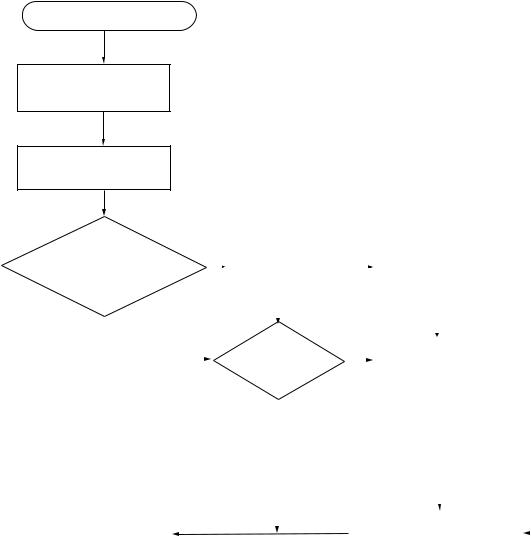
Flow chart for determining if you should/should not transmit DIST ACK signal
DSC Distress alert received.
Press [ALARM STOP] key to silence alarm.
Listen on CH16 for 5 minutes.
|
Did you receive |
|
No |
|
|
|
|
No |
|
|
|
|
No |
||||||
|
acknowledge from |
|
|
Is distress traffic |
|
|
Is distress call |
|
|||||||||||
|
CS and/or RCC? |
|
|
|
|
in progress? |
|
|
|
|
|
continuing? |
|
|
|
|
|||
|
|
|
|
|
|
|
|
|
|
|
|
|
|
||||||
|
|
|
|
|
|
|
|
|
|
|
|
|
|
|
|
|
|
|
|
|
|
|
|
|
|
|
|
Yes |
|
|
|
|
|
|
Yes |
|
|
|
|
|
|
|
|
|
|
|
|
|
|
|
|
|
|
|
|
|
|
||
|
|
|
|
|
|
|
|
|
|
|
|
|
|
|
|
|
|
|
|
|
|
Yes |
|
|
|
|
Is own |
|
|
|
|
|
|
|
|
|
|
|
|
|
|
|
|
|
|
|
|
|
|
|
|
|
|
|
|
|
|||
|
|
|
|
|
|
Yes |
Acknowledge the alert by |
|
|||||||||||
|
|
|
|
|
|
vessel able |
|
||||||||||||
|
|
|
|
|
|
|
|
|
|
|
|
radiotelphony to the ship |
|
||||||
|
|
|
|
|
|
|
to assist? |
|
|
|
|
|
|
||||||
|
|
|
|
|
|
|
|
|
|
|
|
in distress on VHF CH16. |
|
||||||
|
|
|
|
|
|
|
|
|
|
|
|
|
|
|
|||||
|
|
|
|
|
|
|
|
|
|
|
|
|
|
|
|
|
|
|
|
|
|
|
|
|
|
|
|
No |
|
|
|
|
|
|
1. Say "MAYDAY" ONCE. |
||||
|
|
|
|
|
|
|
|
|
|
|
|
|
|
||||||
CS = Coast Station |
|
|
|
|
|
|
|
|
|
|
|
2. Say ID number of vessel |
|||||||
|
|
|
|
|
|
|
|
|
|
|
|
|
in distress THREE TIMES. |
||||||
RCC = Rescue Co-ordination Center |
|
|
|
|
|
|
|
|
3. Say "This is" ONCE. |
||||||||||
|
|
|
|
|
|
|
|
|
|
|
|
|
|
|
4. Say ID number of your vessel |
||||
|
|
|
|
|
|
|
|
|
|
|
|
|
|
|
|
THREE TIMES. |
|||
|
|
|
|
|
|
|
|
|
|
|
|
|
|
|
5. Say "Received MAYDAY" |
||||
|
|
|
|
|
|
|
|
|
|
|
|
|
|
|
|
ONCE. |
|||
|
|
|
|
|
|
|
|
|
|
|
|
|
|
|
|
|
|
|
|
|
|
|
|
|
|
|
|
|
|
Inform CS and/or RCC. |
|
|
|||||||
|
Enter details in log. |
|
|
|
|
|
|
|
|
|
|||||||||
|
|
|
|
|
|
|
|
|
|
||||||||||
|
|
|
|
|
|
|
|
|
|
||||||||||
|
|
|
|
|
|
|
|
|
|
|
|
|
|
|
|
|
|
|
|
3-6
Loading...