


G5
Spindle Orientation
Date: 07/01/04, Rev: 04-07 Page 1 of 14 TM.G5SW.021
Document Name Document Revised Software number Part Number
TM.G5SW.021 07/01/2004 VSG114743 CIMR-G5MXXXXXF-021
A Yaskawa GPD515/G5 AC drive flashed with this software has the ability to control the stopped orientation of the
driven machine. Orientation is achieved by means of feedback from a position encoder directly coupled to the device to
be positioned. The targeted applications are for equipment that must stop in specific positions during the processing
cycle of an operation. Drive enhancements include a definable home position and 15 additional positions relative to
home that can be sequenced automatically or selected through multi-function inputs. A special serial register that does
not require accept or enter commands is provided to enable dynamic control of the stopped position via serial
communications. Drive sequence (start/stop) can come from the terminals (2 or 3 wire control), MODBUS serial
communications, or option board based serial communications (DeviceNet, Profibus, Modbus Plus, etc.). The spindle
orient function will not work in local mode or if the run command source is operator (B1-02 = 0).
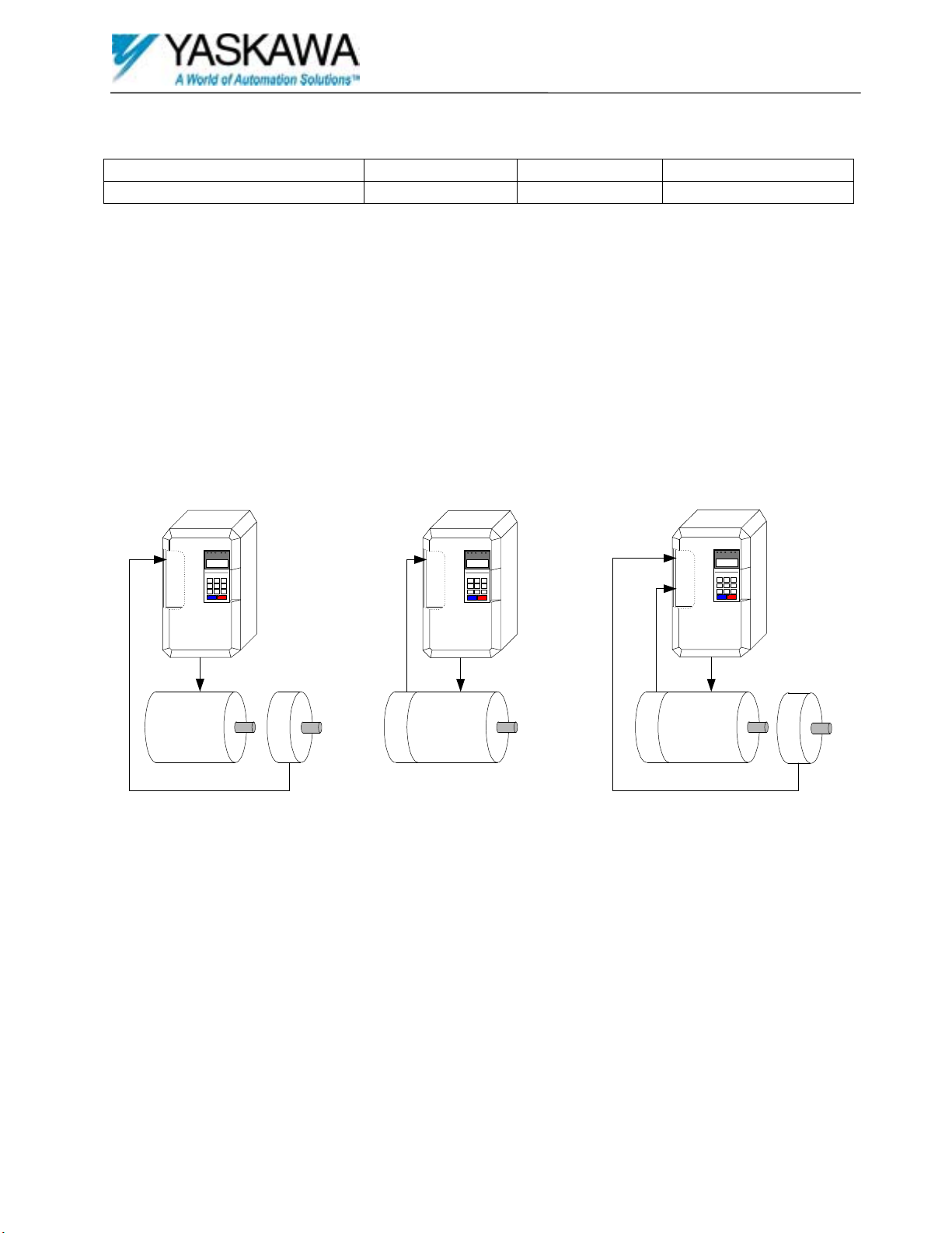
Supported Configurations
PG-X2
Motor / Position
Encoder
Machine
Motor
PG-W2
Motor
Encoder
Machine
Motor
PG-X2
Position
Encoder
Closed Loop Control
With Position Encoder
Closed Loop Control
Open Loop Control
With Position Encoder
Machine
Motor
Position
Encoder

Spindle Orientation
Date: 07/01/04, Rev: 04-07 Page 2 of 14 TM.G5SW.021
Open Loop Control with Position Encoder
The open loop control method may be used when the motor and the device to be positioned are connected through a
drivetrain with a constant ratio. Feedback into a PG option card from the position encoder attached to the device being
positioned is required.
Closed Loop Control
The closed loop control method may be used for better speed control and positioning characteristics when the drive
motor directly drives the device being positioned.
When using this method the motor encoder is used for positioning.
Closed Loop Control with Position Encoder
Closed loop control may be used when the motor and the device to be positioned are connected through a drivetrain with
a constant ratio. Feedback from an encoder attached to the device being positioned is required. This method will
provide better performance than the open loop method.
Spindle Orientation
Date: 07/01/04, Rev: 04-07 Page 3 of 14 TM.G5SW.021
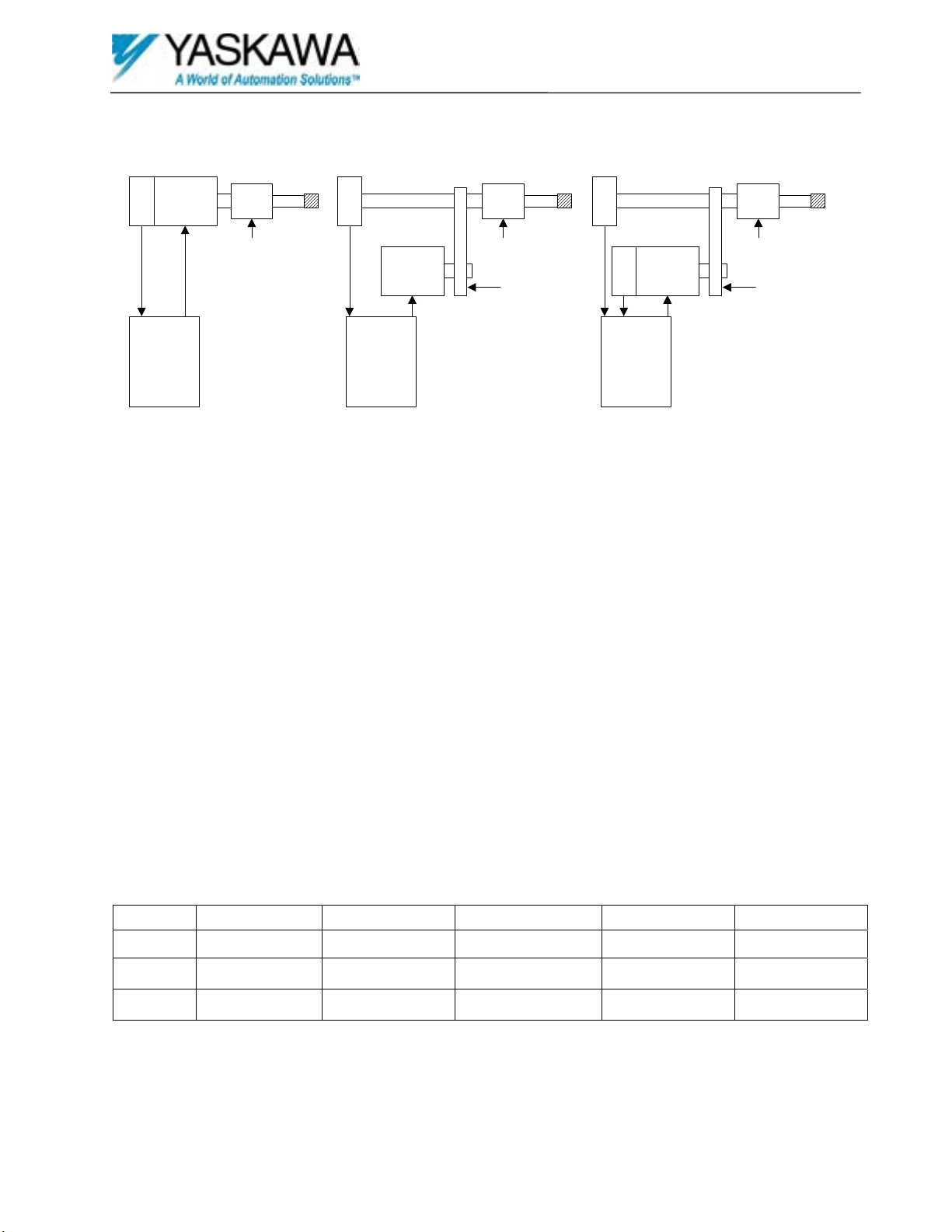
Example Applications
These examples show typical applications. In these examples the encoder Z or marker pulse is used to indicate the zero
or marker position. An external switch may be used as the marker pulse to indicate this position.
Example 1
This is a direct drive system where the encoder, motor and spindle shafts are directly coupled. This system can use the
motor’s encoder for positioning and closed loop vector control of the motor to provide the best performance.
Example 2
This is an indirect drive system where the motor and the spindle shaft are connected through a drive train. The motor
and spindle speeds must have a constant ratio between them. The ratio must be entered into the drive using the provided
ratio parameters. The position encoder is coupled to the spindle shaft. Since there is no motor encoder the drive must be
set to open loop vector control. This configuration will not provide the performance of a closed loop system.
Example 3
This is an indirect drive system where the motor and the spindle shaft are connected through a drive train. The motor
and spindle speeds must have a constant ratio between them. The ratio must be entered into the drive using the provided
ratio parameters. The position encoder is coupled to the spindle shaft. The motor encoder allows for closed loop vector
control. This method will provide the best indirect positioning performance.
Required Components
The application will dictate the required configuration. The configuration will dictate the components needed. The
following table can be used to determine the components needed based on the configurations from the example.
Example Yaskawa Drive Software PG option card Position Encoder Motor Encoder
1 G5 / GPD515 VSG11474X PG-X2 512 to 2048 PPR Not Required
2 G5 / GPD515 VSG11474X PG-X2 512 to 2048 PPR Not Required
3 G5 / GPD515 VSG11474X PG-W2 512 to 2048 PPR 512 to 2048 PPR
All encoders must be quadrature encoders. The position encoder must have a Z pulse or an external switch must be used
to locate the marker position. DO NOT USE PARAMETER F1-05 TO CHANGE ENCODER PHASING WITH
THIS SOFTWARE. PLEASE SWAP ENCODER SIGNALS A+ AND A- INSTEAD.
Yaskawa
Drive with
PG-X2
Option Card
Motor
Encoder
Tool
Chuck
Tool
Drivetrain
Encoder
Motor
Tool
Chuck
ToolSpindle Shaft
Drivetrain
Encoder
Motor
Tool
Chuck
ToolSpi ndle Shaft
Encoder
(Gear Ratio)
(Gear Ratio)
Example 1 Example 2 Example 3
Yaskawa
Drive with
PG-X2
Option Card
Yaskawa
Drive with
PG-W2
Option Card
Positioned Device Positioned Device Positioned Device

Spindle Orientation
Date: 07/01/04, Rev: 04-07 Page 4 of 14 TM.G5SW.021
How it Works
The function of this software is to provide the ability to orient the position encoder and any device connected to it to any
position within the PPR (pulses per revolution) resolution. This requires the position encoder to be directly coupled to
the device to be positioned, which is driven by the drive flashed with VSG11474X software. The position encoder must
also be connected to the drive via a PG option card.
This software has no effect on the normal drive functions and a drive flashed with it can be configured to operate as a
standard drive with a standard software flash. The software is only active when the orient input has been energized.
When that occurs the offset value is read and the drive will accelerate or decelerate to the threshold frequency. The
threshold frequency is determined by 4096 x P1-07: Stop Frequency Gain. If the output frequency of the drive is below
the threshold frequency the drive will accelerate at the rate controlled by C1-01: Accel Time 1. If the output frequency
is above the threshold frequency the drive will begin to decelerate at the rate controlled by C1-02: Decel Time 1. The
drive’s output frequency is monitored. When the output frequency is equal to the threshold frequency the PG card’s Z
pulse is monitored. When a Z pulse is detected the marker position is set and this software begins to orient the position
encoder. The output frequency is dynamically reduced as the position encoder nears the orient position. The orient
position is equal to the marker position plus any additional offset. When the position encoder is within the number of
counts set in P1-05: Position Count of the orient position the output frequency will be set to P1-04: Position Speed. The
drive will maintain this output frequency until the position encoder is within the number of counts set in P1-06: Stop
Count of the orient position where it will stop and zero servo until the orient input or the run input is de-energized. The
orient position maintained will be +/- the counts set in P1-06: Stop Count of the set orient position. This provides a
method to prevent oscillation while the position is being maintained. When this position has been acquired the orient
complete output will activate. If the run input is de-energized while the orient input remains energized the drive will
resume operation where it stopped when the run input is re-energized. The orient complete output will de-activate when
the orient input is de-energized.
The drive will orient the position encoder within two revolutions after the marker position has been set. Revolutions
may be added when needed by incrementing the marker offset value by the quadrature pulse count of the position
encoder. The maximum offset count value is 32767. If you are using a 1024 PPR position encoder the quadrature count
will be 1024 PPR x 4 or 4096 counts per revolution. Using this position encoder, for each 4096 counts added to the
offset the drive will require an additional revolution to orient.
All orientation is done relative to the marker position. The Z pulse from the position encoder or an external-switch
device is required to identify the marker position. P1- 03: Marker Offset parameter is provided to adjust the marker
position to the required or home position. All subsequent offset positions are relative to the home position. The stop
position or orient position is equal to the marker-offset or home position plus the current offset.
To set P1- 03: Marker Offset and identify the home position it is necessary to run the drive and perform an orient by
energizing the orient input. After the drive has stopped and holding position de-energize the run and orient inputs. The
device connected to the position encoder may be rotated into the required or the desired home position. This operation
may be done by hand or by reducing the frequency reference to the drive and using the run inputs to jog the device into
position. When the device is in position the value shown at monitor U1-50: Marker Offset must be entered into P1- 03:
Marker Offset. Monitor U1-50: Marker Offset contains the number of counts past the marker position that the position
encoder has rotated. It is a rolling counter and will restart at zero after the count has exceeded P1-02: Spindle PPR x 4.
(Rolling counter range = 0 to quadrature count –1)
There are four orient control selections. Parameter P1-10: Control Select can be used to select from the following.
0 – Marker Offset – The drive will only use P1- 03: Marker Offset as the orient position when the orient input is
energized. This is the home position.
1 – Sequenced Offset – The drive will automatically increment to the next sequence offset when the orient input is
energized. Parameters P2-01: Offset 1 to P3-05: Offset 15 are used to set the sequence offset values. These
parameters provide 15-sequenced steps. Each step can contain an offset value. When the offset value read is 0 the
sequence step will reset to 0, which is the home position. A sequence-reset input is provided and will reset the step
to 0 or the home position when energized. A home position multifunction output will activate when the sequence is

Spindle Orientation
Date: 07/01/04, Rev: 04-07 Page 5 of 14 TM.G5SW.021
at the home position. After the sequence-reset has reset the sequence step to 0 the next orient input will increment it
to 1 pointing to offset value stored at P2-01 as the first step.
2 – Selected Offset – The offset value to be used can be selected via multifunction inputs. The following selection table
will illustrate how steps can be selected.
Selection Table
Multifunction Inputs Parameter
Number
Step
84: Select MSB 4 85: Select Bit 3 86: Select Bit 2 87: Select LSB 1
P1-03: Marker
Offset
0 Off Off Off Off
P2-01: Offset 1 1 Off Off Off
On
P2-02: Offset 2 2 Off Off
On
Off
P2-03: Offset 3 3 Off Off
On On
P2-04: Offset 4 4 Off
On
Off Off
P2-05: Offset 5 5 Off
On
Off
On
P2-06: Offset 6 6 Off
On On
Off
P2-07: Offset 7 7 Off
On On On
P2-08: Offset 8 8
On
Off Off Off
P2-09: Offset 9 9
On
Off Off
On
P2-10: Offset 10 10
On
Off
On
Off
P3-01: Offset 11 11
On
Off
On On
P3-02: Offset 12 12
On On
Off Off
P3-03: Offset 13 13
On On
Off
On
P3-04: Offset 14 14
On On On
Off
P3-05: Offset 15 15
On On On On
To select step 6 requires multifunction inputs 85: Select 3 and 86: Select 2 to be energized. Multifunction inputs
84:Select MSB 4 and 87: Select LSB 1 must be off or de-energized. The sequence steps are bit mapped to the
multifunction inputs. If the 4 inputs are read as a 4 bit binary number its decimal equivalent is the sequence step.
The selection can be made anytime prior to energizing the orient input. Changing the selection while the orient input
is energized will have no affect until the next orient input.
3 – Serial Offset – The offset value will be read from U1-59: Serial Offset. U1-59: Serial Offset can be written to via
serial communications. The serial offset can be written to anytime prior to energizing the orient input. Changing the
serial offset while the orient input is energized will have no affect until the next orient input. U1-58: Sequence Step
will be set to 99 when this method is used and the serial offset is greater than 0.
The value of the offset entered into an offset parameter is controlled by P3-06: Count or Degree. P1- 03: Marker Offset
is not affected by this parameter and always remains as a count value. P3-06: Count or Degree has the following
selections.
0 – Count – The value entered into the offset parameters are in quadrature encoder counts. (PPR x 4) The number of
counts entered will be used as the offset. This can result in more than one revolution during an orient since 32767
counts can be entered.
1 – Degree – The value entered into the offset parameters are in degrees ranging from 0 to 360 degrees. If the value
entered is greater than 360 it will be reduced to then equivalent position within one revolution. (380 = 20)
All offset counts are measured in the counter-clockwise direction facing the position encoder shaft. All offset degrees
are measured in the clock-wise direction. Because of this increasing the offset count will result in the orient position
moving counter-clockwise and increasing offset degrees will result in the orient position moving clockwise. Either
selection provides for absolute orientation regardless of running direction. If the position encoder’s PPR is 1024, the
marker offset places the home position at 12 o’clock and the offset value is 1024 counts the position encoder will orient
at 1024 counts counter-clockwise past the home position. This is the 9 o’clock position. If the home position is set to
12 o’clock and the offset value is 270 degrees the orient position will be at the 9 o’clock position. Both these statements
are true regardless of running direction.
 Loading...