


Eliminator
GPD515/G5 Software Option (VSG114676)
Part Number: CIMR-G5MXXXXXF-015 (1)
With this factory-installed FLASH software, the GPD515 / G5 becomes a configurable drive.
User Configurable software enhances the standard drive software with embedded functions. The drive may be operated as a standard off the shelf drive or may be configured to utilize the embedded functions. The functions can be configured to create the necessary control logic for many speed or torque control applications. It is possible to reduce the need for external control modules and PLC’s. Whole control systems may be integrated into a stand-alone GPD515 / G5 drive.
With this software, it is possible to read in information and output it into other functions from the following sources;
!All analog inputs
!All PG options
!Drive speed output
!Drive torque output
!Drive Hertz output
!Internal MOP
!Parameters
These sources can be input into the following functions that perform operations to change and control them. The following operations are available;
!Add, subtract, multiply and divide
!Change polarity
!Compare sources
!Absolute value
!PID
!Diameter calculator
!Scale information
!Switch between sources
The outputs from these functions can be connected to other functions or used to control the drive. The drive functions can be used to write information directly to the following drive controls;
!Analog outputs
!Speed reference
!Torque reference
!Multi-function outputs
!Digital Operator Monitors
This software provides the user the flexibility to configure their own logic and to change it when needed. It is one software flash that could replace many.
To better understand what this software can do it is necessary to understand the functions. It is also necessary to understand how to enter the configuration into the drive. The following sections of this manual will explain how to use and setup the functions.
This document is an addendum to Technical Manual TM4515, listing the effect of this software on the parameters in the drive and function descriptions in the manual.
(1) XXXXX refers to the base Model Number of the drive in which the software is installed.
Date: 07/01/04, Rev: 04-07 |
Page 1 of 27 |
TM.G5SW.015 |

Function Blocks - Quick Reference
Source
Term 13 |
|
Term 14 |
|
Term 16 |
|
|
|
Step |
|
PG |
|
|
Analog |
13 |
Analog |
14 |
Analog |
16 |
MOP |
25 |
26 |
Pulse |
0e |
||
MOP |
||||||||||||
Input |
|
Input |
|
Input |
|
|
|
|
Input 1 |
|
||
|
|
|
|
|
|
|
|
|||||
Figure 2.1.1 |
|
|
|
|
|
Figure 2.1.2 |
|
|
|
|
|
|
P1-01 |
|
P1-02 |
|
P1-03 |
9c |
P1-04 |
9d |
P1-05 |
|
PG |
|
|
Number |
9a |
Number |
9b |
Number |
Number |
Number |
9e |
Pulse |
0f |
|||
Input |
|
Input |
|
Input |
|
Input |
|
Input |
|
Input 2 |
|
|
Figure 2.1.3 |
|
|
|
|
|
|
|
|
|
Figure 2.1.4 |
|
|
|
|
|
|
Drive |
|
Drive |
|
Motor |
|
|
|
|
10000 |
12 |
0 |
18 |
15 |
Torque |
11 |
17 |
|
|
|||
Output |
Speed |
|
|
|||||||||
|
|
|
|
|
Output |
|
|
|
|
|||
|
|
|
|
|
|
|
|
|
|
|
||
Figure 2.1.5 |
|
Figure 2.1.6 |
|
Figure 2.1.7 |
|
Figure 2.1.8 |
|
Figure 2.1.9 |
|
|
|
|
Read |
46 |
Read |
47 |
|
|
|
|
|
|
|
|
|
Memory 1 |
Memory 2 |
|
|
|
|
|
|
|
|
|||
|
|
|
|
|
|
|
|
|
|
Figure 2.1.A
Operation
30 |
+ |
32 |
3a |
- |
3c |
50 |
X |
52 |
5a |
/ |
5c |
Absolute |
Change |
|
Value |
Sign |
|||||||||||||
|
|
|
|
|
|
|
|
|||||||
31 |
|
|
3b |
|
|
51 |
|
|
5b |
|
|
|
|
|
|
|
|
|
|
|
|
|
|
|
|
40 |
41 |
||
|
|
|
|
|
|
|
|
|
|
|
|
Figure 2.2.1
70 |
Compare |
|
70 |
Compare |
70 |
Compare |
71 |
70 <= 71 |
74 |
71 |
70 = 71 |
71 |
70 >= 71 |
72 |
False |
72 |
75 |
72 |
76 |
|
|
False |
False |
||||
73 |
True |
|
73 |
True |
73 |
True |
Figure 2.2.2 |
|
|
|
|
|
|
20 |
|
|
01 |
H1-0? = 80 |
04 |
H1-0? = 81 |
Center |
|
|
|
|||
|
22 |
|
03 |
|
06 |
|
|
Winder |
|
|
|||
21 |
|
02 |
|
05 |
|
|
|
|
Switch 1 |
Switch 2 |
|||
|
|
|
|
|
||
Figure 2.2.6 |
Figure 2.2.7 |
Space
10
Figure 2.2.3
H1-0? = 85
42
43
 Hold
Hold
Number
Figure 2.2.8
23 |
PID |
24 |
60 |
Scale |
61 |
Figure 2.2.4 |
|
Figure 2.2.5 |
|
||
Drive
|
ff |
Drive |
|
|
Drive |
|
|
|
Accel/ |
|
Drive |
|
Drive |
|
Drive |
|
|
|
fe |
Max |
|
|
19 |
80 |
81 |
82 |
|||||||
|
Speed |
|
|
|
Decel |
Output 40 |
Output 41 |
Output 42 |
||||||||
|
|
|
|
Torque |
|
|
|
|
|
|||||||
|
|
|
|
|
|
|
|
|
|
|
|
|
|
|
||
Figure 2.3.1 |
|
|
|
Figure 2.3.2 |
|
|
Figure 2.3.3 |
|
Figure 2.3.4 |
|
|
|
|
|||
|
U1-50 |
|
Drive |
|
U1-51 |
|
Drive |
|
U1-52 |
|
U1-53 |
94 |
U1-54 |
|
Write |
|
90 |
|
Analog |
91 |
|
Analog |
92 |
93 |
44 |
||||||||
Monitor |
|
Monitor |
|
Monitor |
Monitor |
Monitor |
Memory 1 |
|||||||||
|
Output 50 |
|
Output 51 |
|
|
|
|
|||||||||
|
|
|
|
|
|
|
|
|
|
|
|
|
||||
|
95 |
U1-55 |
|
96 |
U1-56 |
|
97 |
U1-57 |
98 |
U1-58 |
99 |
U1-59 |
45 |
Write |
||
|
Monitor |
Monitor |
|
Monitor |
Monitor |
Monitor |
Memory 2 |
|||||||||
|
|
|
|
|
|
|
|
|||||||||
Figure 2.3.5 |
|
|
|
|
|
|
|
|
|
|
|
|
|
Figure 2.3.6 |
||
Date: 07/01/04, Rev: 04-07 |
Page 2 of 27 |
TM.G5SW.015 |
Function Block Setup - Quick Reference
Sheet 1 of 2
2.1 Sources |
|
Connections |
|
|
||||
Figure |
Description |
Information |
Input |
|
Output |
|
Setup |
|
2.1.1 |
Analog Input 13 |
Terminal 13 |
|
|
13 |
Terminal 13 can not be reassigned |
||
Analog |
Analog Input 14 |
Terminal 14 |
|
|
14 |
Terminal 14 – H3-09 = 20: Eliminator T-14 |
||
Inputs |
Analog Input 16 |
Terminal 16 |
|
|
16 |
Terminal 16 – H3-05 = 21: Eliminator T-16 |
||
|
|
|
P2-02 = MOP Rate / second |
|
|
|
|
|
2.1.2 |
MOP |
P2-03 = MOP Max Percent |
|
|
25 |
H1-xx = 82: MOP UP |
||
MOP / |
|
|
P2-04 = MOP Min Percent |
|
|
|
H1-xx = 83: MOP DOWN |
|
Step MOP |
Step MOP |
P2-05 = MOP Rst Percent |
|
|
26 |
H1-xx = 84: MOP RESET |
||
|
|
|
|
|
||||
|
P2-06 = MOP Step Rate |
|
|
|
|
|||
|
|
|
|
|
|
|
|
|
2.1.3 |
P1-01 |
Range 0 to 65535 |
|
|
9A |
|
|
|
P1-02 |
Range 0 to 65535 |
|
|
9B |
|
|
||
Number |
P1-03 |
Range 0 to 65535 |
|
|
9C |
|
|
|
Inputs |
P1-04 |
Range 0 to 65535 |
|
|
9D |
|
|
|
|
P1-05 |
Range 0 to 65535 |
|
|
9E |
|
|
|
2.1.4 |
PG Channel 1 |
F1-01 = Pulses Per Rev. |
|
|
0E |
PG Option Card Required (PG-X2 or PG-W2) |
||
|
|
|
||||||
Pulse |
|
|
|
|
|
|
|
|
PG Channel 2 |
P2-01 = Pulses input at 100 % |
|
|
OF |
PG-W2 Option Card Required |
|||
Inputs |
|
|
||||||
inverter speed ( Range 0 to 65535) |
|
|
||||||
|
|
|
|
|
|
|
|
|
2.1.5 |
100 % Reference |
10000 output value |
|
|
12 |
|
|
|
10000 |
|
|
|
|
||||
|
|
|
|
|
|
|
|
|
2.1.6 |
0 % Reference |
0 output value |
|
|
18 |
|
|
|
0 |
|
|
|
|
||||
|
|
|
|
|
|
|
|
|
2.1.7 |
|
|
Percentage of Maximum Frequency |
|
|
|
|
|
Drive |
Output Reference |
|
|
15 |
|
|
||
Output |
|
|
0-10000 output value |
|
|
|
|
|
|
|
|
|
|
|
|
|
|
2.1.8 |
|
|
Percentage of 100.00 Percent Torque |
|
|
|
|
|
Torque |
Torque Reference |
|
|
11 |
|
|
||
0-40000 output value |
|
|
|
|
||||
Output |
|
|
|
|
|
|
|
|
2.1.9 |
Motor Speed |
Available in PG and Vector modes |
|
|
|
|
|
|
Motor |
|
|
17 |
|
|
|||
Percentage |
only |
|
|
|
|
|||
Speed |
|
|
|
|
|
|||
|
|
|
|
|
|
|
|
|
2.1.A |
Read Memory 1 |
Reads the value written into memory |
|
|
46 |
|
Reads Write Memory1 |
|
Read |
|
|
|
|
|
|
|
|
Read Memory 2 |
with the associated write memory. |
|
|
47 |
|
Reads Write Memory 2 |
||
Memory |
|
|
|
|
||||
|
|
|
|
|
||||
2.2 Operations |
|
|
Connections |
|
|
|||
Figure |
Description |
Information |
Input |
|
Output |
|
Information / Equation |
|
|
Addition |
Input Value |
30 |
|
32 |
30 + 31 = 32 |
||
|
Input Value to add |
31 |
|
|||||
|
|
|
|
|
|
|
||
|
Subtraction |
Input Value |
3a |
|
3c |
3a - 3b = 3c |
|
|
2.2.1 |
Input Value to subtract |
3b |
|
|
||||
|
|
|
|
|
|
|||
Multiplication |
Input Value |
50 |
|
52 |
(50 x 51) / 10000 = 52 |
|||
Math |
Input Value to multiply by |
51 |
|
|||||
|
|
|
|
|
|
|||
|
Division |
Input Value |
5a |
|
5c |
(5a x 10000) / 5b = 5c |
||
|
Input Value to divide by |
5b |
|
|||||
|
|
|
|
|
|
|
||
|
Absolute Value |
Same Input / Output Connector |
|
40 |
Absolute Value of X |
|||
|
Change Sign |
Same Input / Output Connector |
|
41 |
X times -1 |
|
||
Date: 07/01/04, Rev: 04-07 |
Page 3 of 27 |
TM.G5SW.015 |

Function Block Setup - Quick Reference
Sheet 2 of 2
|
2.2 Operations |
|
Connections |
|
|
|
||
|
Figure |
Description |
Information |
Input |
Output |
|
Information / Equation |
|
|
|
|
1st Value |
70 |
|
|
|
|
|
|
|
Compared to 1st Value |
71 |
|
|
|
|
|
2.2.2 |
Compare input 70 |
Value if True |
73 |
|
|
|
|
|
Value if False |
72 |
|
|
|
|
||
|
Compare |
to input 71 |
|
|
|
|
||
|
Output less or equal |
|
74 |
70 <= 71 (True: 74 = 73) (False: 74 = 72) |
|
|||
|
|
|
|
|
||||
|
|
|
Output equal |
|
75 |
70 = 71 (True: 75 = 73) (False: 75 = 72) |
|
|
|
|
|
Output greater or equal |
|
76 |
70 >= 71 (True: 76 = 73) (False: 76 = 72) |
|
|
|
|
|
|
|
|
|
||
|
2.2.3 |
Enter Spaces |
Used to enter spaces into a |
|
10 |
|
|
|
|
Space |
configuration |
|
|
|
|
||
|
|
|
|
|
|
|
||
|
|
|
B5-02 PID Gain = P Gain |
|
|
|
|
|
|
2.2.4 |
PID |
B5-03 PID I Time = I Bld Rate |
|
|
|
|
|
|
B5-04 PID I Limit = I Limit |
23 |
24 |
B5-01 PID Mode = Disabled |
|
|||
|
PID |
23 = Error input |
|
|||||
|
B5-05 PID D Time = D Rate |
|
|
|
|
|
||
|
|
|
|
|
|
|
|
|
|
|
|
B5-06 PID Limit = Output Limit |
|
|
|
|
|
|
2.2.5 |
|
P1-08 = Scale Multiplier |
|
|
|
|
|
|
Scale |
P1-09 = Scale Divisor |
60 |
61 |
((60 X P1-08) / P1-09) + P1-10 = 61 |
|
||
|
Scale |
|
||||||
|
|
P1-10 = Scale Bias |
|
|
|
|
|
|
|
|
|
|
|
|
|
|
|
|
2.2.6 |
Calculate Diameter |
Line Speed Ref input |
20 |
|
P1-06 = Diameter Filter Time |
|
|
|
Center |
Diameter Filter Output |
|
22 |
|
|||
|
Winder |
with ratio output |
|
|
|
P1-07 = Diameter Build Ratio |
|
|
|
Motor Speed Ref input |
21 |
|
|
||||
|
2.2.7 |
Switch 1 |
Normally Open |
01 |
03 |
Terminal ? |
- H1-01 to 06 = 80: Switch 1 DI |
|
|
Normally Closed |
02 |
|
|||||
|
Internal |
|
|
|
|
|
||
|
|
Normally Open |
04 |
|
|
|
|
|
|
Switches |
Switch 2 |
06 |
Terminal ? |
- H1-01 to 06 = 81: Switch 2 DI |
|
||
|
Normally Closed |
05 |
|
|||||
|
|
|
|
|
|
|
||
|
2.2.8 |
Hold last input |
Outputs input value until the Hold is |
|
|
|
|
|
|
Number |
activated causing it to hold the last |
42 |
43 |
Terminal ? |
- H1-01 to 06 = 85: Number Hold |
|
|
|
value |
|
||||||
|
Hold |
|
value read.. |
|
|
|
|
|
|
|
|
|
|
|
|
||
|
2.3 Drive |
|
Connections |
|
|
|
||
|
Figure |
Description |
Information |
Input |
Output |
|
Information / Equation |
|
|
2.3.1 |
Frequency |
Controls the drives output frequency |
|
|
|
|
|
|
Drive |
ff |
|
E1-04: Max Frequency Limits the drive output |
|
|||
|
Reference to Drive |
Range 0 to +/- 10000 |
|
|
||||
|
Speed |
|
|
|
|
|
||
|
|
|
|
|
|
|
|
|
|
2.3.2 |
|
Controls the Max output torque from |
|
|
P2-10 = Max Torque Ref (limit) |
|
|
|
Drive Max |
Torque Reference |
the drive. Flux vector control only. |
fe |
|
|
||
|
|
Sets Max torque limit L7-01: Fwd = L7-02: Rev |
|
|||||
|
Torque |
|
Same as changing L7-01 and L7-02. |
|
|
|
||
|
|
|
|
|
|
|
||
|
2.3.3 |
|
Changes the acceleration and |
|
|
Accel Time = (19 x C1-01) / 10000 |
|
|
|
Accel / |
Accel / Decel |
19 |
|
|
|||
|
deceleration time. Accel = Decel |
|
Decel Time = (19 x C1-02) / 10000 |
|
||||
|
Decel |
|
|
|
|
|||
|
|
|
|
|
|
|
|
|
|
2.3.4 |
Contact Output 9 |
Connects terminal 9 to 10 |
80 |
|
H2-01 = 40: CONNECTION 80 |
|
|
|
Drive |
Trans Output 25 |
Sinks terminal 25 to 27 |
81 |
|
H2-02 = 41: CONNECTION 81 |
|
|
|
Outputs |
Trans Output 26 |
Sinks terminal 26 to 27 |
82 |
|
H2-03 = 42: CONNECTION 82 |
|
|
|
2.3.5 |
Monitor 1 (U1-50) |
Information can be passed to analog |
90 |
|
H4-01 or H4-04 = 50: Case Monitor 1 |
|
|
|
Monitor 2 (U1-51) |
output terminals 21 and 23 |
91 |
|
H4-01 or H4-04 = 51: Case Monitor 2 |
|
||
|
Analog / |
|
|
|||||
|
Monitor 3 (U1-52) |
|
92 |
|
|
|
|
|
|
Monitor |
|
|
|
|
|
||
|
Monitor 4 (U1-53) |
|
93 |
|
Monitor Value = Input Value / 10 |
|
||
|
Outputs |
|
|
|
||||
|
Monitor 5 (U1-54) |
|
94 |
|
|
|
|
|
|
|
|
|
|
|
|
||
|
2.3.6 |
Write a value into |
Store numerical data into running |
44 |
|
Number Write 1 |
|
|
|
Write |
the Number Read |
|
|
|
|
|
|
|
memory. Two registers provided. |
45 |
|
Number Write 2 |
|
|||
|
Memory |
registers |
|
|
|
|||
|
|
|
|
|
|
|
|
|
Date: 07/01/04, Rev: 04-07 |
Page 4 of 27 |
|
|
TM.G5SW.015 |
||||
1.0 Configuring The Function Blocks
User Configurable software allows the GPD515/G5 drive to be configured to a specific application. This is accomplished by internal drive functions that may be connected to provide the logic required. For the purposes of understanding and developing logic the internal functions have been reduced to function blocks. The function block diagrams indicate how they can be connected.
Some functions have required setup as multi-function selections to operate. Many functions have associated parameters to provide control. Developing a configuration involves choosing the functions required, connecting them for the required logic and setting the parameters that control the functions.
1.1 Developing a Configuration
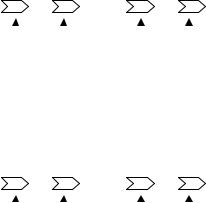
Function blocks are simple block diagrams that indicate their function and how they are connected. The arrow like icons used for the input and output connectors indicate the direction information is moving. A connector number is shown within these icons. Figure 1.1 shows the anatomy of the three categories of functions as function blocks.
|
Source |
|
|
|
|
Operation |
|
|
Drive |
|||||
|
|
|
|
|
|
|
|
|
|
|
|
|
|
|
|
Source |
|
|
|
|
|
|
Convert |
|
|
|
|
|
Drive |
|
Input |
|
# |
# |
|
Source |
|
# |
# |
Output |
||||
|
|
|
||||||||||||
|
Function |
|
|
|
|
|
|
Function |
|
|
|
|
|
Function |
|
|
|
|
|
|
|
|
|
|
|
|
|
|
|
|
|
|
|
|
|
|
|
|
|
|
|
|
|
|
|
|
Output |
Input |
|
Output |
Input |
|
|||||||
Figure 1.1 |
Connector |
Connector |
|
Connector |
Connector |
|
||||||||
|
|
|
|
|
|
|
|
|
|
|
|
|
||
Using function blocks provides a way to develop configurations so they may be understood. From Figure 1.1 it is possible to see how the function blocks may be connected. Figure 1.2 demonstrates how the function blocks are connected.
|
Source |
|
|
|
|
|
|
|
Operation |
|
|
|
Drive |
|||||
|
|
|
|
Connection |
|
|
|
|
Connection |
|
||||||||
|
Source |
|
|
|
Convert |
Drive |
||||||||||||
|
|
|
|
|
|
|
|
|
|
|
|
|
|
|
|
|||
|
Input |
|
01 |
|
|
02 |
|
Source |
|
03 |
|
|
04 |
Output |
||||
|
|
|
|
|
|
|
|
|||||||||||
|
Function |
|
|
|
|
|
|
|
|
Function |
|
|
|
|
|
|
|
Function |
|
|
|
|
|
|
|
|
|
|
|
|
|
|
|
|
|
|
|
|
|
|
|
|
|
|
|
|
|
|
|
|
|
|
|
|
|
|
|
|
Output |
Input |
|
|
Output |
Input |
|
||||||||||
Figure 1.2 |
Connector |
Connector |
Connector |
Connector |
|
|||||||||||||
|
|
|
|
|
|
|
|
|
|
|
|
|
|
|
|
|
||
In figure 1.2 a source input function sends information to the output connector 01. The information is passed through the connection to the input connector 02 of the operation. The operation reads this information and converts it sending the result to the output connector 03. The information is passed through the connection to the input connector 04. The drive output function directs the information to control the drive. All configurations follow this example. There can be more complex configurations with more operations but the basics are the same.
The information starts at a source. It is connected to the operations necessary to convert and control it. The information is then passed to the drive.
Developing a configuration for a drive requires selecting a data source and directing it through operations changing it to information that will provide the proper drive control and then
Date: 07/01/04, Rev: 04-07 |
Page 5 of 27 |
TM.G5SW.015 |
connecting it to the drive function. Configurations can be complex with many sources and operations or as simple as selecting a source reference and connecting it to the drive function.
Once a configuration has been developed using the function blocks to convert source information, it is necessary to enter the configuration into the drive. Entering the configuration into the drive requires generating a configuration list. This list is a record of all connections starting with the beginning information and following the operations in the manner that they must be executed until the information is connected to the drive functions required.
1.2 Configuring The GPD515
Using figure 1.2 a configuration list can be generated by starting at the source output connector 01 and recording the number within it. Next record the number within the input connector 02 that it connects. Follow the information path in the manner that it must be executed. This will yield – 01,02,03,04. The configuration list of connector numbers must be entered into the drive in this sequence.
This software reserves twenty-two User Parameters for the purpose of configuring the GPD515 / G5 drive. The User Parameters are located under the Initialize menu option. Parameters A2-01 through A2-10 remain unchanged serving their standard function. Parameters A2-11 through A2-32 are used for configuring the drive. Configuring the drive requires entering the configuration list into these parameters.
To enter the configuration list into the drive start at A2-11 and enter the first two-connector numbers or the first connection. Enter the next two-connector numbers or the second connection in the next parameter A2-12 and continue this until the complete configuration list has been entered.
Using the configuration list developed for figure 1.2, User Parameter A2-11 will be set to 0102, which are the numbers of the first connection. A2-12 will be set to 0304, which are the numbers of the second connection. When the drive is returned to operation the configuration list will be executed in the sequence that it was entered. The sequence ends at the first 00 connector number, which is the default number for the user parameters. The User Parameter connector numbers are read in the sequence that they are entered. Each connector number results in an operation. Input connectors store the information that is connected to them. Output connectors execute a function to read the stored input connector information or to read information from the drive then the associated function is executed converting the information sending it to the output connector.
1.3 Setup of Functions
Some functions require being selected in the standard drive parameters before they will function. Many functions have parameters and multi-function inputs associated with them. Sections 2 explains the functions, their setup and controls. This information can also be found in the quick reference information. The parameters used for these purposes should be set when the configuration is entered into the GPD515 / G5. Only the parameters required for the current configuration need to be setup.
Date: 07/01/04, Rev: 04-07 |
Page 6 of 27 |
TM.G5SW.015 |
1.4 Configuring Examples
This software may be configured just using the quick references. The following examples will demonstrate that it is just a matter of selecting the needed functions and connecting them together. Once the configuration is finished just record the connector numbers in the sequence that starts at the source information and follows it through the operations in the manner that it must be converted util it is sent to the drive. Then input the connector numbers into the drive.
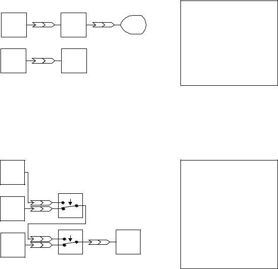
Example 1.4.1:
This configuration will provide a speed reference to the drive and a scaled display monitor for the machine operator.
Terminal 13 |
|
|
|
|
U1-54 |
|
Analog |
13 |
60 |
Scale |
61 94 |
||
Monitor |
||||||
Input |
|
|
|
|
||
|
|
|
|
|
||
Terminal 13 |
13 |
ff |
Drive |
|
|
|
Analog |
Speed |
|
|
|||
Input |
|
|
Control |
|
|
Figure 1.4.1
Configuration List 13,60,61,94,13,ff, 00
Configure the Drive A2-11 = 1360 A2-12 = 6194 A2-13 = 13ff A2-14 = 00XX
XX = Don’t Care
The scaling parameters must be set to control the value displayed by the monitor.
Example 1.4.2:
This configuration uses 2 multi-function inputs to select between the 3 analog inputs to be used as the speed reference.
Terminal 16 |
|
|
|
|
Analog |
|
|
|
|
Input |
|
|
|
|
|
|
H10x : 81 |
|
|
Terminal 14 |
16 |
04 |
|
|
|
|
|
|
|
Analog |
14 |
05 |
|
|
Input |
|
Switch 2 DI |
|
|
|
|
|
|
|
|
|
H10x : 80 |
|
|
Terminal 13 |
06 |
01 |
ff |
Drive |
|
03 |
Speed |
||
Analog |
13 |
02 |
|
Control |
Input |
|
Switch 1 DI |
|
|
|
|
|
|
Figure 1.4.2
Configuration List 16,04,14,05,06,01,13,02,03, ff, 00
Configure the Drive A2-11 = 1604 A2-12 = 1405 A2-13 = 0601 A2-14 = 1302 A2-15 = 03ff A2-16 = 00XX
XX = Don’t Care
The multi-function and analog inputs must be setup. The drive will use terminal 13 as a reference with both switches off. When switch 1 is on via the multi-function input, terminal 14 becomes the reference. When both switches are on via the multi-function inputs, terminal 16 becomes the reference.
Date: 07/01/04, Rev: 04-07 |
Page 7 of 27 |
TM.G5SW.015 |
1.5 Advanced Topics / Examples
The configuration entered in the A2 User Parameters is a sequence of numbers that are read back and executed by connector numbers. Each A2 parameter can contains one connection point or two connector numbers. Each connector number must be two digits. When the connector number is a single digit a 0 must be added to make it two. The leading zeros must be entered.
When a connector is read into the drive the function it represents is executed. Upon completion the next connector or two digit number is read and executed. This continues until a 00 is read or until all 22 A2 parameters or all 44 connector numbers have been executed.
The connectors are always read in sequence starting at the beginning and finishing at the end. The complete sequence is read each scan. The process starts over again on the next scan.
All operation input connectors store the connected input value without changing it. Because of this it is possible to connect values to all operation inputs before entering the output connector number into the sequence. When an operation output connector is read and executed the current stored input or last read values will be used and a new value is calculated and output. This must be considered when using an operation more than one time. Each time it is used all the inputs must only be in the sequence one time before the output is entered. After the output is entered it is possible to reuse the operation inputs but the output must be entered again before the end of the configuration sequence.
It is also possible to reduce the numbers required in the sequence by only entering an output one time when it is connected to several inputs. Once the output has been executed, the current value that will be passed to all input connectors is unchanged until the next output is executed. Therefore all input connectors that connect to an output may be entered into the configuration sequence after the output and before the next output. Outputs change the current value that will be passed. Inputs do not change the current or last output value.
Despite the flexibility provided with this software there are some configurations that may not be possible. The following examples demonstrate what has been covered in this section.
Date: 07/01/04, Rev: 04-07 |
Page 8 of 27 |
TM.G5SW.015 |
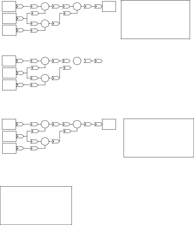
Example 1.5.1: |
|
This will function properly |
|
|
|
|
||||
Term 13 |
|
|
+ |
|
|
+ |
|
ff |
Drive |
|
Analog |
13 |
30 |
32 |
30 |
32 |
|||||
Speed |
||||||||||
Input |
|
|
|
|
|
|
||||
|
|
|
|
|
|
|
|
|
||
Term 16 |
|
31 |
|
31 |
|
|
|
|
||
|
|
|
|
|
|
|
|
|
||
Analog |
16 |
|
|
|
|
|
|
|
|
|
Input |
|
3a |
- |
3c |
|
|
|
|
|
|
|
|
|
|
|
|
|
||||
|
|
|
|
|
|
|
|
|||
Term 14 |
|
|
|
|
|
|
|
|
|
|
Analog |
14 |
3b |
|
|
|
|
|
|
|
|
Input |
|
|
|
|
|
|
|
|
|
|
Figure 1.5.1 |
|
|
|
|
|
|
|
|
|
|
Example 1.5.2: This will not function as intended
Configuration List 13,30,16,31,16,3a,14,3b,32,30,3c,31,32,ff
Configure the Drive |
|
|
A2-11 = 1330 |
A2-15 |
= 3230 |
A2-12 = 1631 |
A2-16 |
= 3c31 |
A2-13 = 163a |
A2-17 |
= 32ff |
A2-14 = 143b |
A2-18 |
= 00XX |
XX = Don’t Care
Term 13
Analog 13 30
Input
31
Term 16
Analog 16
Input
30
Term 14
Analog 14 31
Input
Figure 1.5.2
+
+
32 |
30 |
|
|
|
|
|
32 |
ff |
Drive |
|
Configuration List |
|
|
+ |
|
Speed |
|
13,30,16,31,16,30,14,31,32,30,32,31,32,ff |
|||||||||
|
|
|
|
|
|
||||||||
|
31 |
|
|
|
|
|
|
|
|
|
Configure the Drive |
|
|
|
|
|
|
|
|
|
|
|
|
|
|
||
|
|
|
|
|
|
|
|
|
|
|
|
||
|
|
|
|
|
|
|
|
|
|
|
|
|
|
|
|
|
|
|
|
|
|
|
|
|
A2-11 = 1330 |
A2-15 |
= 3230 |
32 |
|
|
|
|
|
|
|
|
|
|
A2-12 = 1631 |
A2-16 |
= 3231 |
|
|
|
|
|
|
|
|
|
|
A2-13 = 1630 |
A2-17 |
= 32ff |
|
|
|
|
|
|
|
|
|
|
|
|
|||
|
|
|
|
|
|
|
|
|
|
|
A2-14 = 1431 |
A2-18 |
= 00XX |
|
|
|
|
|
|
|
|
|
|
|
XX = Don’t Care |
|
|
|
|
|
|
|
|
|
|
|
|
|
|
|
|
In this example output 32 will provide the value from the last execution to both connected inputs.
Example 1.5.3 |
|
This will function properly |
|
|
|
|
||||
Term 13 |
13 |
30 |
+ |
32 |
3a |
- |
3c |
ff |
Drive |
|
Analog |
||||||||||
Speed |
||||||||||
Input |
|
|
|
|
|
|
||||
|
|
|
|
|
|
|
|
|
||
Term 16 |
|
31 |
|
3b |
|
|
|
|
||
16 |
|
|
|
|
|
|
|
|
||
Analog |
|
|
|
|
|
|
|
|
||
Input |
|
30 |
+ |
32 |
|
|
|
|
|
|
|
|
|
|
|
|
|
||||
|
|
|
|
|
|
|
|
|||
Term 14 |
14 |
|
|
|
|
|
|
|
|
|
Analog |
31 |
|
|
|
|
|
|
|
||
Input |
|
|
|
|
|
|
|
|
|
|
Figure 1.5.3 |
|
|
|
|
|
|
|
|
|
|
Configuration List
13,30,16,31,32, 3a,16,30,14,31,32,3b,3c,ff
Configure the Drive |
|
|
A2-11 = 1330 |
A2-15 |
= 1431 |
A2-12 = 1631 |
A2-16 |
= 323b |
A2-13 = 323a |
A2-17 |
= 3cff |
A2-14 = 1630 |
A2-18 |
= 00XX |
XX = Don’t Care
Example 1.5.4 |
Figure 1.5.1 above can be reduced as shown |
Reduced List Figure 1.5.1 13,30,16,31,3a, 14,3b, 32, 30, 3c, 31, 32, ff
Configure the Drive |
|
|
A2-11 = 1330 |
A2-15 |
= 303c |
A2-12 = 1631 |
A2-16 |
= 3132 |
A2-13 = 3a14 |
A2-17 |
= ff00 |
A2-14 = 3b32 |
A2-18 |
= XX |
Figures 1.5.2 and 1.5.3 cannot be reduced. The common output 16 must be input to the addition function for each execution since a function will use the last value input for each execution. If output 16 was connected to input 31 on both addition functions it could be reduced since input 31 would remain the same for both executions.
Date: 07/01/04, Rev: 04-07 |
Page 9 of 27 |
TM.G5SW.015 |
 Loading...