


MX200-12

MIXING CONSOLE
TABLE DE MIXAGE
MISCHPULTE
CONSOLA DE MEZCLA
Operation Manual
Manuel d’instructions
Bedienungsanleitung
Manual de Operación
123456789
123456789
123456789
OUT IN
A
A
A
A
A
A
A
20dB
–16
–15 +15
–15
–15
010
0
0
0
LR
PFL
B
B
B
B
20dB
–16
80
–15 +15
HIGH
–15
–15
LOW
010
AUX 1
0
AUX 2
0
AUX 3
0
AUX 4
LR
PAN
PFL
B
20dB
20dB
–16
–16
–60
–60
–60
GAIN
GAIN
GAIN
PEAK
PEAK
PEAK
80
80
–15 +15
–15 +15
HIGH
HIGH
+15
+15
+15
–15
–15
MID
MID
MID
+15
+15
+15
–15
–15
LOW
LOW
P
P
P
010
010
R
R
R
AUX 1
AUX 1
E
E
E
0
0
10
10
10
AUX 2
AUX 2
P
P
P
10
10
10
0
0
O
O
O
AUX 3
AUX 3
S
S
S
T
T
0
0
10
10
10
AUX 4
AUX 4
LR
LR
PAN
PAN
PFL
PFL
10
10
10
5
5
5
0
0
0
5
5
5
10
10
10
15
15
15
20
20
20
30
30
30
40
40
40
00
00
00
20dB
–16
–60
–60
GAIN
GAIN
PEAK
PEAK
80
80
–15 +15
HIGH
HIGH
+15
+15
–15
MID
MID
+15
+15
–15
LOW
LOW
P
P
010
R
R
AUX 1
AUX 1
E
E
0
10
10
AUX 2
AUX 2
P
P
10
10
0
O
O
AUX 3
AUX 3
S
S
T
T
0
10
10
AUX 4
AUX 4
LR
PAN
PAN
PFL
10
10
5
5
0
0
5
5
10
10
15
15
20
20
30
30
40
40
00
00
A
B
B
B
20dB
20dB
20dB
–16
–16
–16
–60
–60
GAIN
GAIN
GAIN
PEAK
PEAK
PEAK
80
80
80
–15 +15
–15 +15
–15 +15
HIGH
HIGH
HIGH
+15
+15
–15
–15
–15
MID
MID
MID
+15
+15
–15
–15
–15
LOW
LOW
LOW
P
P
010
010
010
R
R
AUX 1
AUX 1
AUX 1
E
E
0
0
0
10
10
AUX 2
AUX 2
AUX 2
P
P
10
10
0
0
0
O
O
AUX 3
AUX 3
AUX 3
S
S
T
T
T
0
0
0
10
10
AUX 4
AUX 4
AUX 4
LR
LR
LR
PAN
PAN
PAN
PFL
PFL
PFL
10
10
5
5
0
0
5
5
10
10
15
15
20
20
30
30
40
40
00
00
10 11 12 13 14 15 16 17 18 19 20 21 22 23 24
INPUT A
10 11 12 13 14 15 16 17 18 19 20 21 22 23 24
INPUT B
10 11 12 13 14 15 16 17 18 19 20 21 22 23 24
A
B
20dB
–16
–60
GAIN
PEAK
80
–15 +15
HIGH
+15
–15
MID
+15
–15
LOW
P
010
R
AUX 1
E
0
10
AUX 2
P
10
0
O
AUX 3
S
T
0
10
AUX 4
LR
PAN
PFL
10
5
0
5
10
15
20
30
40
00
INPUT CH INSERT I/O 0dB
A
A
A
A
20dB
–16
–15 +15
–15
–15
010
0
0
0
LR
PFL
A
B
B
B
20dB
20dB
–16
–16
–60
–60
–60
GAIN
GAIN
GAIN
PEAK
PEAK
PEAK
80
80
80
–15 +15
–15 +15
HIGH
HIGH
HIGH
+15
+15
+15
–15
–15
MID
MID
MID
+15
+15
+15
–15
–15
LOW
LOW
LOW
P
P
010
010
R
R
R
AUX 1
AUX 1
AUX 1
E
E
0
0
10
10
10
AUX 2
AUX 2
AUX 2
P
P
10
10
10
0
0
O
O
O
AUX 3
AUX 3
AUX 3
S
S
T
T
0
0
10
10
10
AUX 4
AUX 4
AUX 4
LR
LR
PAN
PAN
PAN
PFL
PFL
10
10
10
5
5
5
0
0
0
5
5
5
10
10
10
15
15
15
20
20
20
30
30
30
40
40
40
00
00
00
B
B
20dB
20dB
–16
–16
–60
–60
–60
GAIN
GAIN
PEAK
PEAK
80
80
–15 +15
–15 +15
HIGH
HIGH
+15
+15
+15
–15
–15
MID
MID
+15
+15
+15
–15
–15
LOW
LOW
P
P
P
010
010
R
R
R
AUX 1
AUX 1
E
E
E
0
0
10
10
10
AUX 2
AUX 2
P
P
P
10
10
10
0
0
O
O
O
AUX 3
AUX 3
S
S
S
T
T
T
0
0
10
10
10
AUX 4
AUX 4
LR
LR
PAN
PAN
PFL
PFL
10
10
10
5
5
5
0
0
0
5
5
5
10
10
10
15
15
15
20
20
20
30
30
30
40
40
40
00
00
00
A
A
A
A
A
B
B
B
20dB
20dB
20dB
–16
–16
–16
–60
–60
–60
GAIN
GAIN
GAIN
PEAK
PEAK
PEAK
80
80
80
–15 +15
–15 +15
–15 +15
HIGH
HIGH
HIGH
+15
+15
+15
–15
–15
–15
MID
MID
MID
+15
+15
+15
–15
–15
–15
LOW
LOW
LOW
P
P
P
010
010
010
R
R
AUX 1
AUX 1
AUX 1
E
E
E
0
0
0
10
10
10
AUX 2
AUX 2
AUX 2
P
P
P
10
10
10
0
0
0
O
O
AUX 3
AUX 3
AUX 3
S
S
S
T
T
T
0
0
0
10
10
10
AUX 4
AUX 4
AUX 4
LR
LR
LR
PAN
PAN
PAN
PFL
PFL
PFL
10
10
5
5
0
0
5
5
10
10
15
15
20
20
30
30
40
40
00
00
12345678
A
B
B
B
20dB
20dB
20dB
–16
–16
–16
–60
–60
GAIN
GAIN
GAIN
PEAK
PEAK
PEAK
80
80
80
–15 +15
–15 +15
–15 +15
HIGH
HIGH
HIGH
+15
+15
–15
–15
–15
MID
MID
MID
+15
+15
–15
–15
–15
LOW
LOW
LOW
P
P
P
010
010
010
R
R
R
AUX 1
AUX 1
AUX 1
E
E
E
0
0
0
10
10
AUX 2
AUX 2
AUX 2
P
P
P
10
10
0
0
0
O
O
O
AUX 3
AUX 3
AUX 3
S
S
S
T
T
T
0
0
0
10
10
AUX 4
AUX 4
AUX 4
LR
LR
LR
PAN
PAN
PAN
PFL
PFL
PFL
10
10
10
5
5
5
0
0
0
5
5
5
10
10
10
15
15
15
20
20
20
30
30
30
40
40
40
00
00
00
RR
LL
LR
–10dB
–10dB
TAPE IN REC OUT
1R
1L/MONO2R2L/MONO
OUT IN
A
A
B
B
20dB
20dB
20dB
–16
–16
–16
–60
–60
–60
GAIN
GAIN
PEAK
PEAK
80
80
–15 +15
–15 +15
–15 +15
HIGH
HIGH
+15
+15
+15
–15
–15
–15
MID
MID
+15
+15
+15
–15
–15
–15
LOW
LOW
P
P
P
010
010
010
R
R
R
AUX 1
AUX 1
E
E
E
0
0
0
10
10
10
AUX 2
AUX 2
P
P
P
10
10
10
0
0
0
O
O
O
AUX 3
AUX 3
S
S
S
T
T
T
0
0
0
10
10
10
AUX 4
AUX 4
LR
LR
LR
PAN
PAN
PFL
PFL
PFL
10
10
10
5
5
5
0
0
0
5
5
5
10
10
10
15
15
15
20
20
20
30
30
30
40
40
40
00
00
00
AUX RETURN +4dB
A
A
B
B
20dB
–16
–60
–60
GAIN
GAIN
PEAK
PEAK
80
80
–15
–15
+15
HIGH
HIGH
+15
–15 +15
–15
–15
–15
010
0
0
0
LR
ONONONONONONONON
PFL
HIGH
MID
LOW
AUX 1
AUX 2
AUX 3
AUX 4
PAN
+15
+15
P
R
E
10
P
10
O
S
T
10
10
5
0
5
10
15
20
30
40
00
–15
LOW
0
0
10
AUX 1
AUX 1
0
0
10
LEVEL
LEVEL
AUX RETURN 1AUX RETURN 2
10
5
0
5
10
15
20
30
00
ON
10
5
0
5
10
15
20
30
40
00
L ST R
LOW
HIGH
+15
MID
+15
LOW
P
R
AUX 1
E
10
AUX 2
P
10
O
AUX 3
S
T
10
AUX 4
PAN
10
5
0
5
10
15
20
30
40
00
+4B
STEREO OUT +4dB
MONO OUT
314
2
AUX SEND +4dB
MIXING CONSOLE
+6
+6
+4
+4
+2
+2
0
0
+15
–2
–2
–4
–4
–7
–7
+15
–10
–10
–15
–15
–20
–20
–00
–00
10
L ST R
MONO PFL/AFL
1 AUX 2
3 AUX 4
METER SELECT
10
PHANTOM
10
10
10
5
0
5
10
15
20
30
00
10
5
0
5
10
15
20
30
40
00
5
0
5
10
15
20
30
00
AFLAFLAFL AFL
ON
AFL
10
5
0
5
10
15
20
30
40
00
PFL
5
0
5
10
10
15
0
REC OUT
20
30
00
0
10
TAPE IN
AUX SEND 4AUX SEND 3AUX SEND 2AUX SEND 1
010
PHONES
PHONESMONO

Introduction
Thank you for purchasing a Yamaha MX200 Mixing Console. The MX200 series provides an
excellent balance of operability, functionality and ease of use. In order to take full advantage of the
MX200’s capabilities and enjoy years of trouble-free use, please read this manual carefully.
Features
● The MX200-8 provides 8 channels of input (the MX200-
12 has 12 channels, the MX200-16 has 16 channels, and
the MX200-24 has 24 channels) that can be mixed down to
a stereo signal.
● The MONO OUT output provides a convenient connection
for a sub amp for monitoring, or for checking phase cancellation.
● The PFL (Pre Fader Listen) function allows you to monitor
any input channel before the channel fader.
● The AFL (After Fader Listen) function allows you to
monitor the output signal from ST OUT L,R, MONO OUT
or AUX SEND through headphones at any time.
● XLR type connectors are provided for the INPUT A jacks
and phone connectors are provided for the INPUT B jacks,
allowing easy connections with a variety of input sources.
The inputs can accept levels ranging from microphones to
line level devices.
● Phantom power is provided for easy connection of con-
denser microphones requiring an external power supply.
● Each input channel has an INPUT CH INSERT I/O jack,
allowing you to connect effect devices independently for
each channel.
● Four AUX SEND systems and two stereo AUX RETURN
systems are provided. Even when two 1-in/2-out effect devices are connected, two more AUX SEND systems are
still available for use.
● The TAPE IN and REC OUT jacks provide convenient
connections for tape deck playback and recording.
Contents
Precautions ............................................................................1
Control panel .........................................................................2
Channel control section ...................................................2
Master control section......................................................4
Connectors .......................................................................6
Rear panel .............................................................................. 7
Application Example ............................................................. 8
Specifications ........................................................................9
General specifications......................................................9
Input specifications ........................................................ 10
Output specifications .....................................................10
Block and level diagrams...............................................11
Dimensions ....................................................................12

Precautions
1. Avoid Excessive Heat, Humidity, Dust and Vibration
Keep the unit away from locations where it is likely to be
exposed to high temperatures or humidity — such as near
radiators, stoves, etc. Also avoid locations which are
subject to excessive dust accumulation or vibration which
could cause mechanical damage.
2. Ventilation
The unit has ventilation slots on the side and bottom
panels. Do not block these vents.
3. Avoid Physical Shocks
Strong physical shocks to the unit can cause damage.
Handle it with care.
4. Do Not Open the Case or Attempt Repairs or Modifications Yourself
This product contains no user-serviceable parts. Refer all
maintenance to qualified Yamaha service personnel.
Opening the case and/or tampering with the internal
circuitry voids the warranty.
5. Always power off before making connections
Always turn the power OFF before connecting or disconnecting cables. This is important to prevent damage to the
unit itself as well as other connected equipment.
6. Handle Cables Carefully
Always plug and unplug cables — including the AC power
cord — by gripping the connector, not the cord.
7. Clean With a Soft Dry Cloth
Never use solvents such as benzine or thinner to clean the
unit. Wipe clean with a soft, dry cloth.
8. Always Use the Correct Power Supply
Make sure that the power supply voltage specified on the
rear panel matches your local AC mains supply. Also make
sure that the AC mains supply can deliver more than
enough current to handle all equipment used in your
system.
Dette apparat overholder det gaeldende EF-direktiv
vedtrørende radiostøj.
Cet appareil est conforme aux prescriptions de la directive
communautaire 87/308/CEE.
Diese Geräte entsprechen der EG-Richtlinie 82/499/EWG
und/oder 87/308/EWG.
This product complies with the radio frequency interference
requirements of the Council Directive 82/499/EEC and/or
87/308/EEC.
Questo apparecchio è conforme al D.M.13 aprile 1989
(Direttiva CEE/87/308) sulla soppressione dei radiodisturbi.
Este producto está de acuerdo con los requisitos sobre
interferencias de radio frequencia fijados por el Consejo
Directivo 87/308/CEE.
YAMAHA CORPORATION
IMPORTANT NOTICE FOR
THE UNITED KINGDOM
Connecting the Plug and Cord
IMPORTANT: The wires in this mains lead are coloured in
accordance with the following code:
BLUE : NEUTRAL
BROWN : LIVE
As the colours of the wires in the mains lead of this
apparatus may not correspond with the coloured markings
identifying the terminals in your plug, proceed as follows:
The wire which is coloured BLUE must be connected to the
terminal which is marked with the letter N or coloured
BLACK.
The wire which is coloured BROWN must be connected to the
terminal which is marked with the letter L or coloured RED.
Making sure that neither core is connected to the earth
terminal of the three pin plug.
This applies only to products distributed by YAMAHA KEMBLE MUSIC (U.K.)
*
LTD.
1
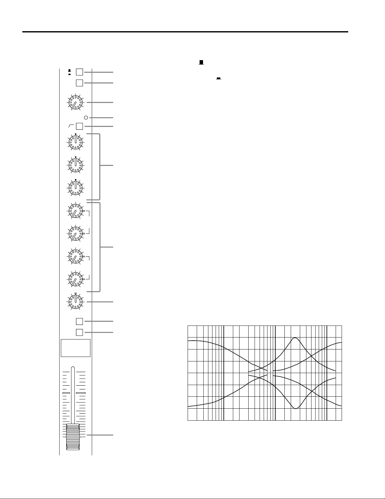
Control panel
20 50100 200 500 1k 2k 5k 10k 20k
FREQUENCY (Hz)
+20
+15
+10
+5
0
–5
–10
–15
–20
RESPONSE (dB)
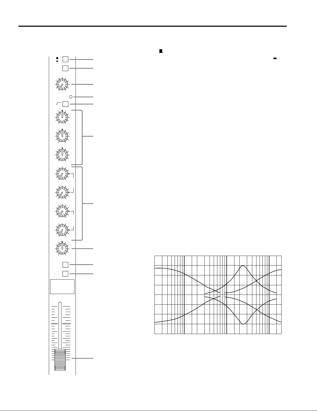
■ Channel control section
A
B
20dB
–16
–60
GAIN
PEAK
80
–15 +15
HIGH
+15
–15
MID
+15
–15
LOW
010
AUX 1
0
10
AUX 2
10
0
AUX 3
0
10
AUX 4
LR
PAN
ON
PFL
P
R
E
P
O
S
T
1
2
3
4
5
6
7
8
9
0
1 Input selector
This button selects the input connector for the channel.
When A ( ) is selected, the input signal will be taken from the rear
panel INPUT A connector (balanced XLR type). When B ( ) is
selected, the input signal will be taken from the rear panel INPUT B connector (balanced phone jack).
2 PAD switch
This pad switch provides 20dB of level reduction.
If the input signal level is too high and the 3 GAIN control will not
reduce it sufficiently, use this pad switch.
3 GAIN control
According to the level of the input signal, use this knob to adjust the input
to an appropriate level.
The best balance of S/N and dynamic range will be achieved if you adjust
the GAIN control so that the 4 peak indicator lights occasionally. If you
wish to further reduce the input level, use the 2 PAD switch.
4 PEAK indicator
This indicator detects peak levels after the EQ.
It will light red at 3dB before clipping to warn that clipping level has
nearly been reached.
5 80Hz high-pass filter switch
This switch turns on/off a high-pass filter that cuts the signal below 80Hz
at 12dB/octave.
6 Equalizer
The equalizer section provides ±15dB of control over the high, mid and
low ranges at the following frequencies.
HIGH: 12kHz
MID: 2.5kHz
LOW: 80Hz
Frequency response will be flat when the knob is at the “▼” position.
10
2
5
0
5
10
15
20
30
40
00
A
7 AUX1–4 controls
These knobs control the level of the signals sent to the
AUX buses.
• The AUX1 and AUX2 controls are pre-fader, and the
signal levels sent to the AUX 1 and 2 buses will be unaffected by the channel fader setting.
• The AUX3 and AUX 4 controls are post-fader, and the
signal levels sent to the AUX 3 and 3 buses will be affected by the channel fader setting.
8 PAN (panpot) control
This knob assigns the signal of each channel to the
STEREO L, R bus, determining the stereo position of the
sound.
9 Channel ON switch
When this switch is on, the signal of each channel will be
sent to the STEREO L, R bus and the AUX1–4 buses.
When this switch is off, the output signal to each bus will
be muted completely. This switch should be turned off for
unused channels.
0 Channel PFL switch
This switch allows you to monitor the pre-fader channel
input signal through headphones.
It is convenient to use PFL when you wish to check the
sound of the input signal, or when troubleshooting a
specific channel.
A Channel fader
This fader controls the output level of the input channel
signal, determining the volume balance between channels.
The channel fader should be lowered for unused channels.
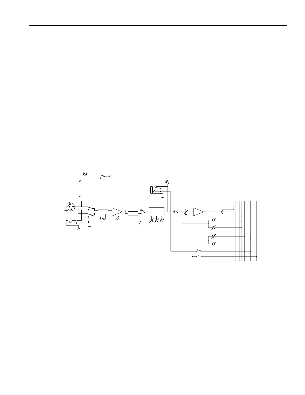
INPUT A
INPUT B
1-*
1-*
PHANTOM
(INPUT A)
(PHANTOM)
*=8,12,16,24
OFF
ON
PHANTOM
A
20dB GAIN
B
(+48V)
HAPAD
INPUT CH
INSERT I/O
0dB 1-*
HPF
PEAK
CTRL
STEREO
AUX
1RL
3BAND
EQ
80
MID
LOW
HIGH
ON
(+V)
PAN
AUX 1
AUX 2
AUX 3
PFL
AFL
PFL
AFL
PFL
432
3
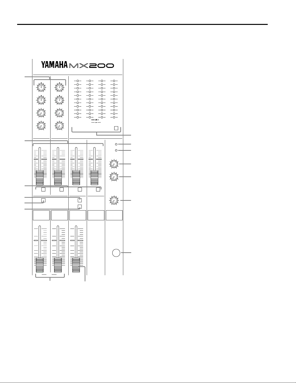
■ Master control section
MIXING CONSOLE
8
–15
–15
AUX RETURN 1 AUX RETURN 2
7
6
3
1
4
0
AUX 1
0
LEVEL
ON
HIGH
LOW
–15
+15
+15
10
10
10
5
0
5
10
15
20
30
00
+15
HIGH
+15
–15
LOW
0
10
AUX 2
0
10
LEVEL
10
5
0
5
10
15
20
30
00
+6
+4
+2
0
–2
–4
–7
–10
–15
–20
–00
L ST R
1 AUX 2
10
5
0
5
10
15
20
30
00
AFLAFLAFL AFL
ON
AFL
AUX SEND 4AUX SEND 3AUX SEND 2AUX SEND 1
+6
+4
+2
0
–2
–4
–7
–10
–15
–20
–00
MONO PFL/AFL
3 AUX 4
METER SELECT
10
5
0
5
10
15
0
REC OUT
20
30
00
0
010
PHANTOM
PFL
TAPE IN
PHONES
1 STEREO ON switch
This switch turns the ST OUT output on/off.
When this switch is off, levels will not be displayed in the
ST meters. The MONO OUT signal will be sent regardless
of this switch.
2 STEREO L, R master faders
These faders adjust the final level of the combined signals
from all channels, and send them from the STEREO OUT
connectors.
The ST meters allow you to monitor the L and R outputs.
3 MONO ON switch
This switch turns the MONO OUT on/off.
4 MONO AFL switch
When this switch is on, the signal being output to MONO
OUT can be monitored in the headphones.
C
D
E
9
10
0
10
A
5 MONO fader
This fader adjusts the output level of the MONO OUT connector.
6 AUX SEND 1–4 AFL switches
When you wish to monitor the output signals being sent to
AUX SEND 1–4, press the appropriate switch.
The level of the AUX SEND whose switch is on will be indicated by the PFL/AFL meter.
7 AUX SEND faders
These faders adjust the level of the output signals sent from
AUX SEND 1–4.
The 8 METER SELECT switch can be set so that these
AUX SEND signals are monitored in the level meters.
10
5
0
5
10
15
20
30
40
00
L ST R
10
5
0
5
10
15
20
30
40
00
10
5
0
5
10
15
20
30
40
00
PHONESMONO
B
8 AUX RETURN 1, 2 controls
<LEVEL>
The LEVEL knobs control the level at which signals from
effect units etc. connected to the L/MONO, R jacks of
AUX RETURN 1, 2 are sent to the L, R bus.
If a plug is inserted into only the L/MONO jack, the same
signal will be sent to both L and R buses.
<AUX1 (AUX2)>
The AUX1 knobs control the level at which signals from
52
effect units etc. connected to the L/MONO, R jacks of
AUX RETURN 1, 2 are sent to the AUX SEND 1 (2) fader.
After being adjusted at the fader, the signal is output from
the rear panel AUX SEND 1 (2).
<LOW>
This knob is a low frequency equalizer that provides 80Hz
shelving equalization of the signal input at AUX
RETURN.
4
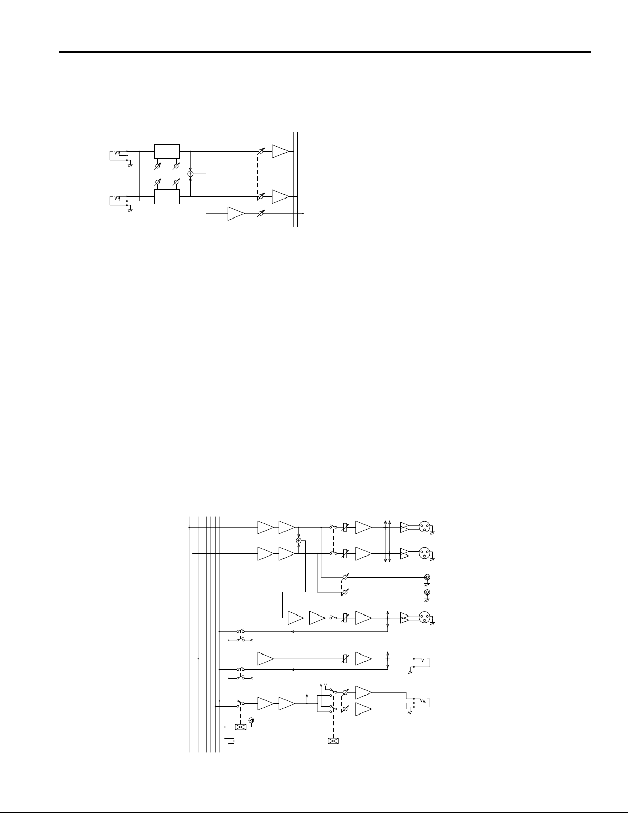
<HIGH>
This knob is a high frequency equalizer that provides
12kHz shelving equalization of the signal input at AUX
RETURN.
L
AUX RETURN
1 +4dB
R
2BAND
EQ
LOW
2BAND
EQ
HIGH
SUM
LEVEL
AUX 1
INV
INV
9 REC OUT control
This knob adjusts the output level of the REC OUT jacks
(connector 5) connected to a tape deck, etc.
0 TAPE IN control
This knob adjusts the monitor volume of a tape deck etc.
connected to the TAPE IN jacks.
A PHONES control
This knob adjusts the volume of a set of headphones connected to the headphone jack (PHONES).
B PHONES jack
Connect the headpones here.
You can monitor the following signals:
— Signals available for monitoring —
• The main signal output to the ST OUT jacks (Turn off
all PFL and AFL switches.)
• The signals input to each input channel and processed
through the 3-band EQ and the INPUT CH INSERT I/
O jack (Turn on a channel PFL switch.)
• The signal output to MONO OUT (Turn on the MONO
OUT AFL switch.)
• The AUX signals output from each AUX SEND 1–4
jack (Turn on an AUX SEND 1–4 AFL switch.)
C METER SELECT switch and meter section
The meters are dual-function LED meters that indicate
signal levels as selected by the METER SELECT switch.
<When METER SELECT is OFF>
• STEREO L,R ...... displays the output levels of the
STEREO OUT jacks.
• MONO OUT level ...... displays the output level of the
MONO OUT jack.
• PFL/AFL level ...... displays the input level of the
channel whose PFL switch is on, or the output level of
the ST, MONO OUT, or AUX SEND jack whose AFL
switch (master control section 4, 6) is on.
<When METER SELECT is ON>
• AUX SEND 1–4 ...... displays the level of the AUX signals output to the AUX SEND 1–4 jacks.
D PHANTOM indicator
This indicator will be lit when the PHANTOM switch (rear
panel 2) is on.
E PFL indicator
This indicator will be lit when any of the channel PFL
switches (channel control section 0) is on.
At this time, the PFL/AFL meter in the meter section will
indicate the level of the channel whose PFL switch is on.
STEREO
1RL
AUX
CTRL
AFL
PFL
AFL
PFL
432
INV
SUM
INV
SUM
SUM
(+V)
AFL
SUM INV
(+V)
AFL
SUM
PFL
(METER)
INV
INV
(ST OUT)
ON
REC OUT
ON
PHONES
(METER)
(PHONES)
(METER)
(METER)
L
STEREO OUT
+4dB
R
L
REC OUT
-10dBv
R
MONO OUT
+4dB
AUX SEND
1-4 +4dB
PHONES
5
■ Connectors
1
12345678
2
3
12345678
12345678
OUT IN
INPUT A
INPUT B
INPUT CH INSERT I/O 0dB
OUT IN
45 6 7
RR
LL
–10dB
TAPE IN REC OUT
1R
1L/MONO2R2L/MONO
AUX RETURN +4dB
LR
–10dB
STEREO OUT +4dB
3
1
AUX SEND +4dB
4
2
9
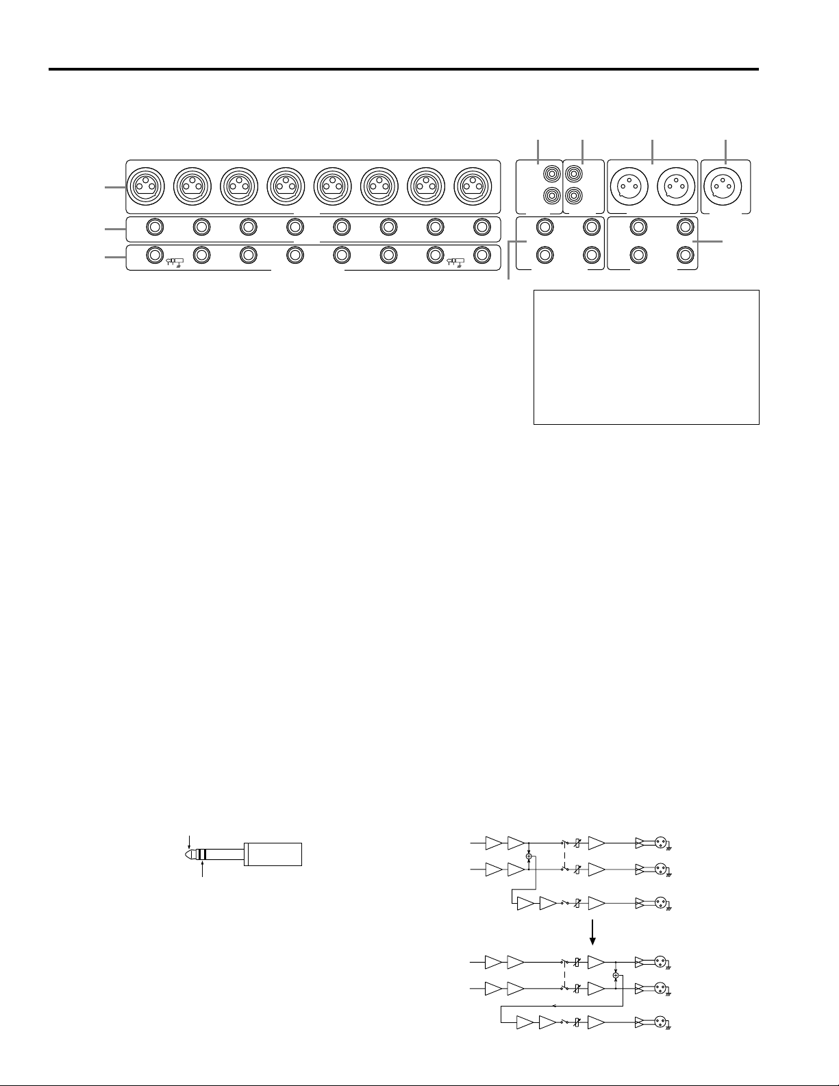
MICROPHONE CABLES AND
MICROPHONES CONNECTION
TO PREVENT HAZARD OR DAMAGE,
ENSURE THAT ONLY MICROPHONE
CABLES AND MICROPHONES
DESIGNED TO THE IEC268-15A
STANDARD ARE CONNECTED.
+4dB
MONO OUT
8
1 INPUT A
These are XLR type connectors.
(1: sleeve, 2: hot, 3: cold)
Microphones of 50–600Ω or 600Ω line level devices can
be connected here.
When the PHANTOM switch (rear panel 2) is turned on,
DC+48V will be supplied to pins 2 and 3 of these connectors.
2 INPUT B
These are balanced phone connectors.
(T: hot, R: cold, S: sleeve)
Microphones of 50–600Ω or 600Ω line level devices can
be connected here.
Unbalanced phone plugs can also be connected, however,
noise may occur with long cables, or cables subjected to strong
electromagnetic fields caused by radio and TV broadcasts.
3 INPUT CH INSERT I/O 0dB
These are input/output jacks located between the head amp
and the equalizer of the input channel section.
The nominal input level and impedance is 0dB/600Ω, and
the nominal output level and impedance is 0dB/10kΩ.
These jacks allow you to insert your own graphic
equalizers, compressors, noise filters, or other devices.
INSERT OUT
INSERT IN
4 TAPE IN
Your DAT or cassette deck can be directly connected here
for convenient monitoring. Use the TAPE IN control
(master control section 0) to adjust the level.
5 REC OUT
Your DAT or cassette deck can be connected here to
record the audio signal from STEREO OUT.
6
In this case, the final output level is adjusted by the REC
OUT control (master control section 9), and the STEREO
L,R fader settings will have no affect.
6 STEREO OUT (L, R)
This is the stereo output of the combined audio signals.
Connect these jacks to the power amp that drives your
main speakers.
Alternatively, you can record the output from these jacks if
you wish to use the STEREO L,R faders to adjust the audio
level being recorded.
7 MONO OUT
This is the MONO OUT output jack. The MONO OUT can
be used for simple recordings of a live performance, for
driving a sub power amp, or to check for phase
cancellation.
An internal jumper can be reconnected to change the
location of the MONO OUT to post-ST fader. If this is
done, the MONO OUT signal will be affected by the STEREO ON switch.
Internal jumper wires can be changed to move the MONO
OUT signal so that it is taken after the ST fader. If you would
like this change to be made, consult with your dealer.
INV
SUM
INV
SUM
SUM
INV
SUM
INV
SUM
SUM
ON
INV
ON
ON
INV
ON
L
STEREO OUT
R
MONO OUT
L
STEREO OUT
R
MONO OUT
8 AUX SEND (1, 2, 3, 4)
These are unbalanced jacks with a nominal output and impedance of +4dB/600Ω. (AUX 1 and 2 are pre-fader, and
AUX 3 and 4 are post-fader.)
9 AUX RETURN (1L/MONO, 1R, 2L/MONO, 2R)
These are unbalanced jacks with a nominal input level and
impedance of +4dB/10 kΩ.
These jacks are usually used to receive the audio returned
from an effect unit such as reverb or delay, but they can
also be used as supplementary inputs.
If a plug is inserted only in L/MONO, the same signal will
be sent to both the L and R buses.
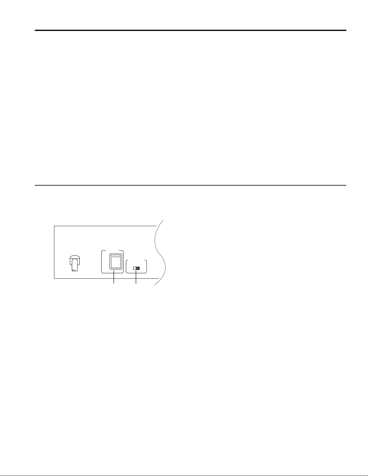
Rear panel
1 POWER switch
This switch turns on the power of the mixer.
When turning off the power of audio equipment, it is important to start with the device closest to the speakers.
(Normally, this will be the power amp.)
POWER
ON
OFF
PHANTOM
12
2 PHANTOM switch
This switch turns on/off the phantom power supply for all
channels.
OFFON
Use this switch when you are using condenser
microphones.
When this switch is turned on, DC +48V will be supplied
to pins 2 and 3 of each INPUT A XLR connector.
If you do not need phantom power, be sure to leave this
turned off.
* It is safe to connect balanced dynamic microphones or
line level devices even if this switch is left on, but connecting unbalanced devices or devices whose transformers are center-grounded will cause hum or
malfunctions.
7
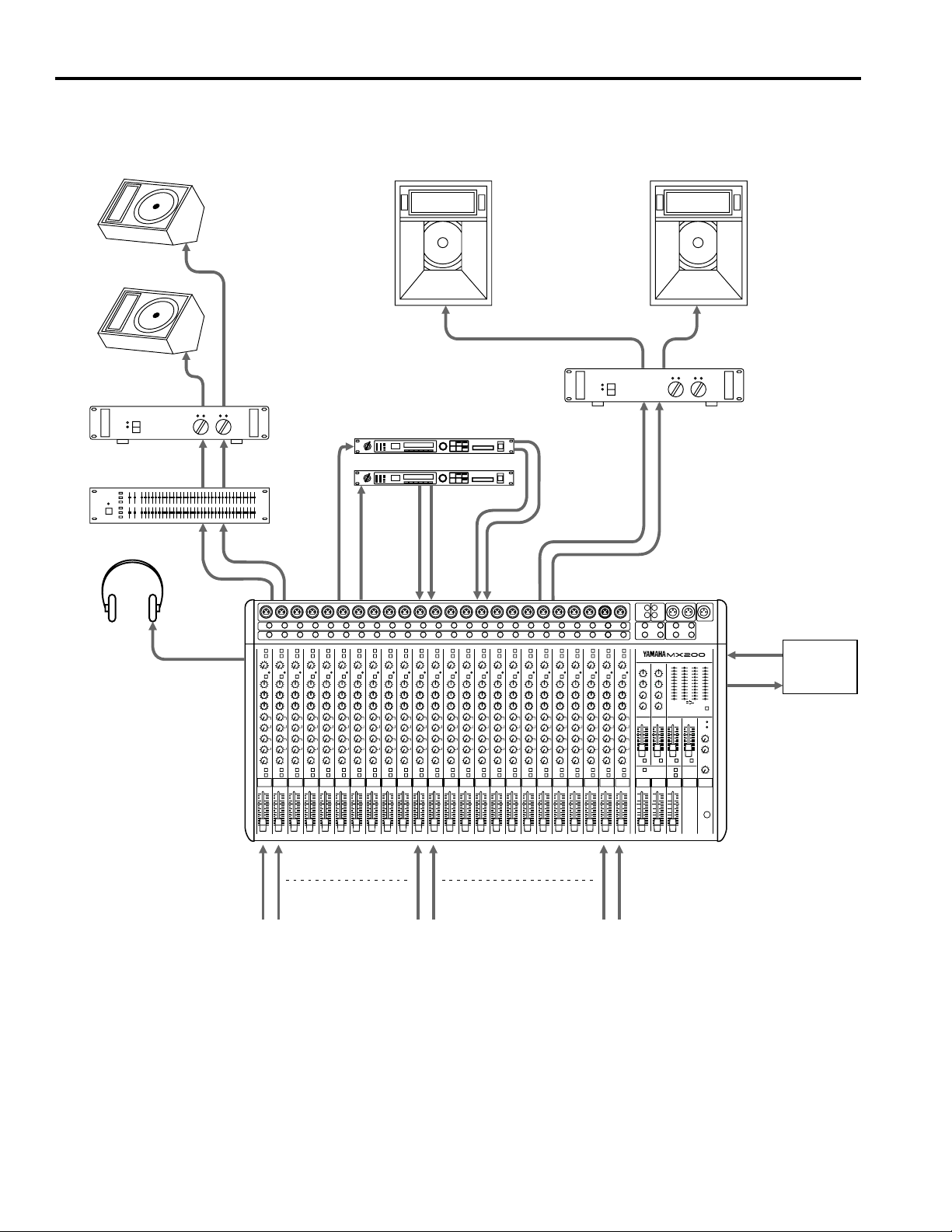
Application Example
Stagemonitors
Poweramp
Frontofhouse
mainspeakers
Poweramp
Effects processor
88
GraphicEQ
Headphone
AUX SEND1
AUX SEND2
AUX
SEND3
88
AUX
SEND4
AUX
RTN2
AUX
RTN1
STEREO
OUT
MIXING CONSOLE
TAPE IN
REC OUT
Cassette
Deck or
DAT
Micandlineinput
8
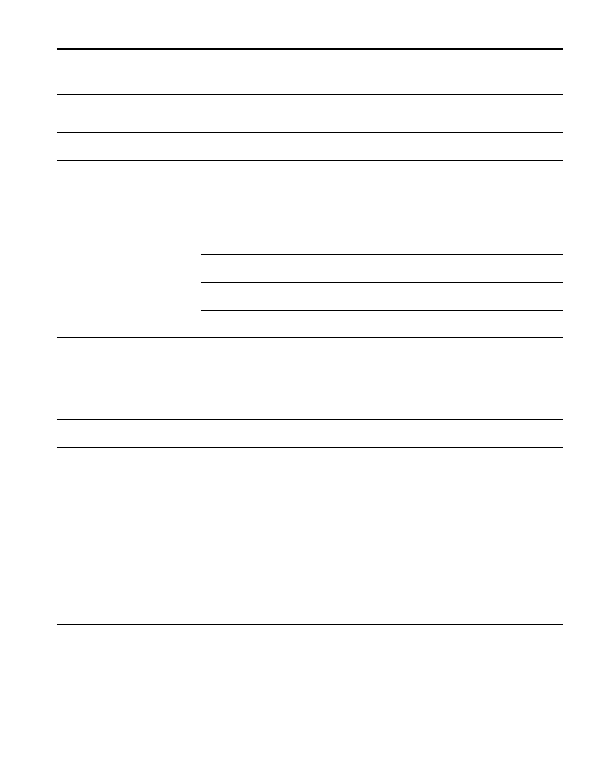
Specifications
■ General specifications
Maximum output level +24dB (STEREO L/R) @600Ω, 0.5% THD at 1kHz
+24dB (MONO OUT) @600Ω, 0.5% THD at 1kHz
+20dB (AUX SEND) @600Ω, 0.5% THD at 1kHz
Total harmonic distortion < 0.1% @+14dB 20Hz–20kHz
(ST L/R, MONO, AUX SEND @600Ω)
Frequency response 20Hz–20kHz +1dB, –2dB
(ST L/R, MONO, AUX SEND @600Ω)
Hum and noise –127dB equivalent input noise
(Average, Rs=150Ω) –95dB residual output noise (STEREO L/R, MONO)
(Measured with DIN AUDIO) –95dB residual output noise (AUX SEND 1–4)
–88dB (STEREO, MONO) Master fader at nominal level, and all channel
assign switches off.
–63dB (67dB S/N) (STEREO, MONO) Master fader and one channel fader at nomi-
nal level.
–78dB (AUX SEND 1–4) AUX SEND master fader at nominal level, and
all channel assign switches off.
–63dB (67dB S/N) (AUX SEND 1–4) AUX SEND master fader and one channel
AUX at nominal level.
Maximum voltage gain 84dB CH IN to STEREO OUT
84dB CH IN to MONO OUT
80dB CH IN to AUX SEND 1, 2
90dB CH IN to AUX SEND 3, 4
16dB AUX RETURN 1, 2 to STEREO OUT
16dB AUX RETURN 1, 2 to AUX SEND 1, 2
28dB TAPE In 1, 2 to STEREO OUT
Crosstalk at 1kHz –70dB between input channels
–70dB between output channels
Gain control (input channel) 44dB variable (–60– –16dB)
Pad switch (input channel) 0/20dB
Input channel equalization ±15dB maximum boost or cut
HIGH: 12kHz shelving
MID: 2.5kHz peaking
LOW: 80Hz shelving
* Turnover/rolloff frequencies: located 3dB below maximum boost/cut
LED meters 10-segment LED × 4
POWER (–∞)
STEREO L/AUX SEND 1 (switchable)
STEREO R/AUX SEND 2 (switchable)
MONO/AUX SEND 3 (switchable)
PFL or AFL/AUX SEND 4 (switchable)
Channel peak indicators
An indicator for each channel turns on when the pre-channel fader signal is 3dB below clipping.
Phantom power +48V, DC
Power supply/Power consumption
US and Canadian model MX200-8 120V AC 60Hz 45W, MX200-12 120V AC 60Hz 55W
MX200-16 120V AC 60Hz 65W, MX200-24 120V AC 60Hz 80W
General model MX200-8 230V AC 50Hz 45W, MX200-12 230V AC 50Hz 55W
MX200-16 230V AC 50Hz 65W, MX200-24 230V AC 50Hz 80W
British model MX200-8 240V AC 50Hz 45W, MX200-12 240V AC 50Hz 55W
MX200-16 240V AC 50Hz 65W, MX200-24 240V AC 50Hz 80W
9

Dimensions (W × H × D) 449 × 124.6 × 461.7 mm MX200-8
569 × 124.6 × 461.7 mm MX200-12
689 × 124.6 × 461.7 mm MX200-16
929 × 124.6 × 461.7 mm MX200-24
Weight 9.5kg MX200-8
11kg MX200-12
13.5kg MX200-16
17kg MX200-24
■ Input specifications
0dB=0.775 Vrms
Input connectors
PAD
CH Input
OFF
(0dB)
ON
(20dB)
AUX RETURN
(1, 2) (195mV) (1.23V) (7.75V) phone jack
INSERT IN 5kΩ
TAPE IN 10kΩ
Input impedance Nominal impedance
Gain
trim clipping
–60 50–600Ω mic
4kΩ &
–16
600Ω line
10kΩ
600Ω line –20dB 0dB +20dB Phone jack (TRS)
Sensitivity Nominal level
–80dB –60dB –40dB INPUT A
(77.5µV) (775µV) (7.75mV) XLR 3-31 type
–36dB –16dB +4dB
(12.3mV) (123mV) (1.23V)
–16dB +4dB +24dB Phone jack (TRS)
(123mV) (1.23V) (12.3V)
–12dB +4dB +20dB Unbalanced
(77.5mV) (775mV) (7.75V) T=OUT,R=IN, S=GND
–26dBV –10dBV
(50.1mV) (316mV)
Input level
Max. before
— RCA pin jack
Connector type
balanced
INPUT B
T=hot, R=cold, S=GND
0dB=0.775 Vrms
0dBV=1 Vrms
■ Output specifications
Output connector Output impedance Nominal impedance
Nominal Max. before clipping
Output level
Connector type
STEREO OUT L/R,
MONO OUT
REC OUT L/R 2kΩ 10kΩ Lines –10dBV (316mV) +16dBV (6.31V) RCA pin jack
AUX SEND 1–475Ω 600Ω Line +4dB (1.23V) +20dB (7.75V) Phone jack
INSERT OUT 600Ω 10kΩ Line 0dB (775mV) +20dB (7.75V)
PHONES (head phone) OUT
Specifications and appearance are subject to change without notice for product improvement.
150Ω 600Ω Lines +4dB(1.23V) +24dB (12.3V) XLR-3-32 type
Phone jack (TRS)
T=OUT, R=IN, S=GND
100Ω 40Ω Phones 3mW 120mW ST phone jack
0dB=0.775 Vrms
0dBV=1 Vrms
10
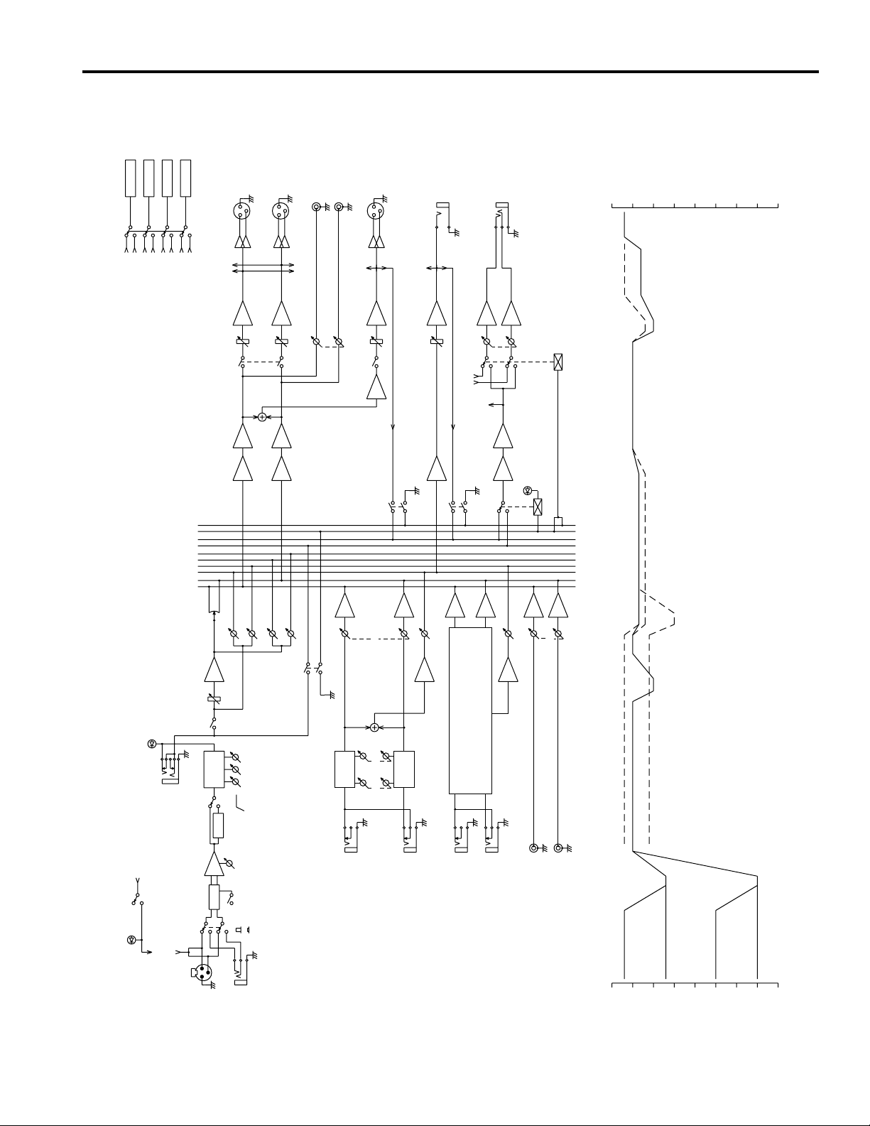
■ Block and level diagrams
METER
METER
(ST OUT L)
(ST OUT R)
(AUX SEND 1)
(AUX SEND 2)
METER
METER
(PHONES)
(MONO OUT)
(AUX SEND 4)
(AUX SEND 3)
AFL
CTRL
PFL
AFL
PFL
4
3
AUX
2
1
R
STEREO
L
L
METER SELECT
(METER)
SUM INV
+4dB
STEREO OUT
R
ON
INV
SUM
L
(PHONES)
-10dBv
REC OUT
R
(METER)
REC OUT
+4dB
MONO OUT
ON
SUM
(METER)
AFL
1-4 +4dB
AUX SEND
INVSUM
(ST OUT)
(METER)
AFL
PHONES
INVSUM
PFL
PHONES
+10
AUX SEND ST
0
MONO
STEREO
AUX
-70
-60
-50
-40
-30
-20
-10
PEAK
(+48V)
ON
OFF
PHANTOM
INSERT I/O
INPUT CH
PHANTOM
(INPUT A)
(PHANTOM)
0dB 1-*
3BAND
HAPAD
1-*
INPUT A
EQ
HPF
PAN
ON
AUX 1
80
GAIN
20dB
A
B
1-*
INPUT B
AUX 2
HIGH
MID
LOW
AUX 4
AUX 3
*=8,12,16,24
PFL
INV
EQ
2BAND
L
INV
LEVEL
EQ
2BAND
LOW HIGH
R
+4dB
AUX RETURN 1
SUM
INV
INV
AUX 1
Same as AUX RETURN 1
L
R
+4dB
AUX RETURN 2
SUM
AUX 2
L
TAPE IN
-10dBv
TAPE IN
TAPE IN
AUX RETURN
R
GAIN MIN
(dB) (dB)
+10
PAD ON
0
PAD OFF
-10
GAIN MIN
-20
GAIN MAX
GAIN MAX
PAD OFF
PAD ON
-70
-60
-50
-40
-30
11
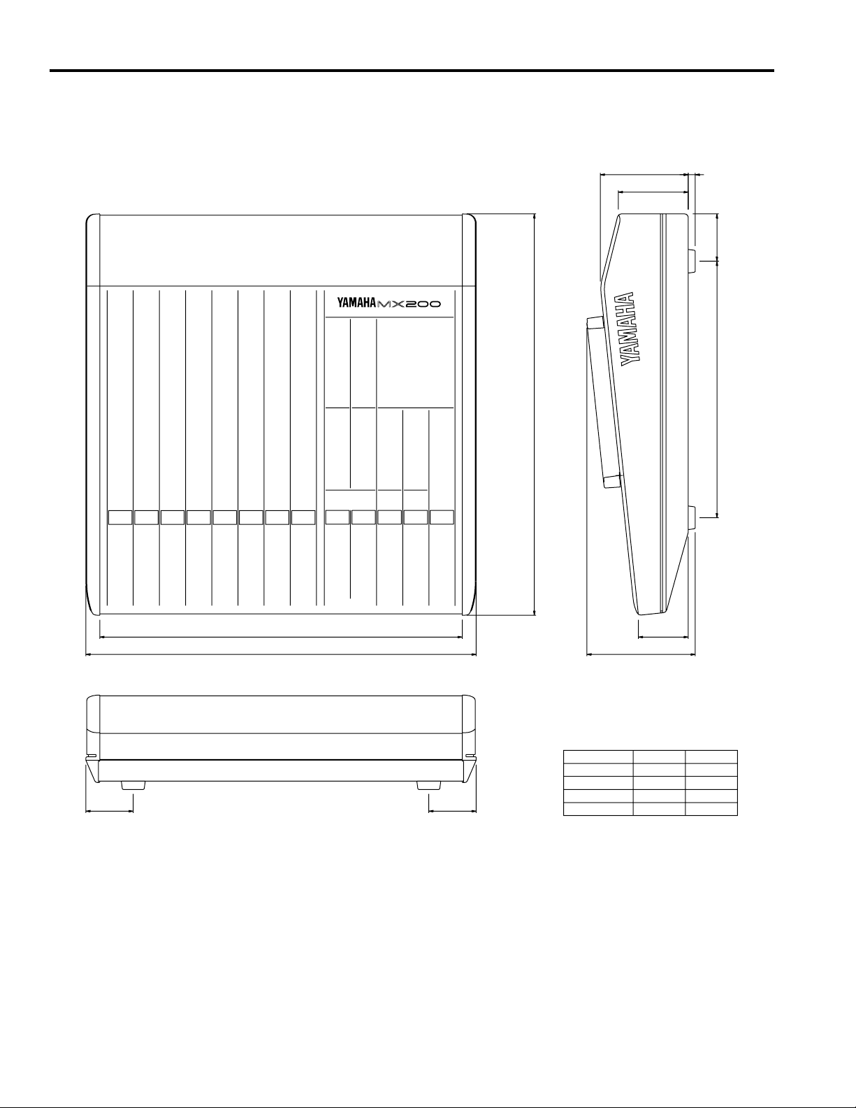
■ Dimensions
8101.2
80.6
295 54.5
D: 461.7
Wi
57.3
W
MODEL
MX200-8
MX200-12
(54.5)(54.5)
MX200-16
MX200-24
H: 124.6
417
537
657
897
Wi
W
449
569
689
929
Units: mm
12

TABLE DE MIXAGE
Manuel d’instructions
Français

Introduction
Nous vous remercions d’avoir fait l’acquisition d’une console de mixage MX200 Yamaha. La série
MX200 apporte un excellent équilibre entre fonctionnalité et facilité d’emploi. Afin de tirer pleinement partie des possibilités du MX200 et de garantir des années d’utilisation sans problème, lire attentivement ce manuel.
Caractéristiques
● Le MX200-8 possède 8 canaux d’entrée (le MX-200-12
possède 12 canaux, le MX200-16 possède 16 canaux, et le
MX200-24 possède 24 canaux) qui peuvent être mixés en
signal stéréo.
● La sortie mono (MONO OUT) possède une connexion pra-
tique pour un sous-ampli de contrôle, ou pour vérifier l’annulation de phase.
● La fonction PFL (écoute pré-fader) permet de contrôler
tout canal d’entrée avant le fader du canal.
● La fonction AFL (écoute post-fader) permet de contrôler le
signal de sortie stéréo (ST OUT) G, D (sortie stéréo gauche
et droite), de sortie mono (MONO OUT) ou de sortie auxiliaire (AUX SEND) avec un casque à n’importe quel moment.
● Des connecteurs de type XLR sont fournis pour les prises
d’entrée (INPUT A) et des connecteurs de casque sont
fournis pour les prises d’entrée B (INPUT B), permettant
des connexions faciles avec diverses sources d’entrée. Les
entrées acceptent des niveaux allant des microphones aux
appareils de niveau de ligne.
● L’alimentation fantôme est fournie pour une connexion fa-
cile des microphones à condensateur nécessitant une alimentation externe.
● Chaque canal d’entrée possède une prise E/S d’insertion de
canal (INPUT CH INSERT I/O), permettant de connecter des
processeurs d’effets indépendamment pour chaque canal.
● Quatre systèmes de sortie auxiliaire (AUX SEND) et deux
systèmes stéréo de retour auxiliaire (AUX RETURN) sont
fournis. Même lorsque deux processeurs d’effets 1-entrée/
2-sortie sont connectés, deux systèmes de sortie auxiliaire
(AUX SEND) supplémentaires sont toujours disponibles
pour l’utilisation.
● Les prises d’entrée cassette (TAPE IN) et de sortie d’enre-
gistrement (REC OUT) permettent des connexions pratiques pour la lecture et l’enregistrement sur platine cassette.
Table des matières
Précautions ............................................................................1
Panneau de commande ..........................................................2
Section de contrôle de canal ............................................2
Section de contrôle principale.......................................... 4
Connecteurs .....................................................................6
Panneau arrière ......................................................................7
Exemple d’application...........................................................8
Caractéristiques ..................................................................... 9
Caractéristiques générales................................................ 9
Caractéristiques d’entrée................................................ 10
Caractéristiques de sortie ............................................... 10
Schémas de connexions et de niveaux ........................... 11
Dimensions .................................................................... 12

Précautions
1. Evitez tout emplacement excessivement chaud, humide, poussiéreux ou soumis à des vibrations
Ne placez pas l’appareil dans un endroit où il risque d’être
exposé à des températures élevées ou une forte humidité
(évitez la proximité de radiateurs, poêles, etc). Evitez également les endroits poussiéreux ou soumis à des vibrations
qui peuvent être à l’origine de dommages mécaniques.
2. Ventilation
L’appareil est pourvu de fentes d’aération sur les panneaux
latéraux et inférieur. Ne bloquez jamais ces fentes.
3. Evitez tout choc
Un choc relativement important peut endommager l’appareil. Maniez-le donc avec soin.
4. N’ouvrez pas le boîtier et n’essayez pas d’effectuer des
réparations vous-même
Cet appareil ne contient pas d’élément pouvant être réparé
par l’utilisateur. Veuillez donc confier toute réparation à
un technicien Yamaha qualifié. Toute tentative d’ouverture du boîtier et de manipulation des circuits internes se
soldera par la perte du bénéfice de la garantie.
5. Coupez toujours l’alimentation avant de procéder à des
branchements
N’oubliez jamais de mettre les appareils hors tension avant
de brancher ou de débrancher des câbles afin de ne pas endommager l’appareil lui-même ainsi que le matériel qui y
est branché.
6. Manipulez les câbles avec soin
Pour brancher et débrancher des câbles (y compris le câble
d’alimentation), prenez-le toujours par la prise et non par
le câble.
7. Nettoyez avec un chiffon doux et sec
N’utilisez jamais de solvants, tels que du benzène ou un diluant pour nettoyer l’appareil. Prenez les poussières avec
un chiffon doux et sec.
8. Utilisez toujours une source d’alimentation adéquate
Assurez-vous que la tension spécifiée sur l’arrière de l’appareil correspond bien à celle de votre secteur et que les
prises utilisées peuvent assurer le courant nécessaire pour
faire fonctionner tout votre système.
1
Panneau de commande
20 50100 200 500 1k 2k 5k 10k 20k
FREQUENCY (Hz)
+20
+15
+10
+5
0
–5
–10
–15
–20
RESPONSE (dB)
■ Section de contrôle de canal
A
B
20dB
–16
–60
GAIN
PEAK
80
–15 +15
HIGH
+15
–15
MID
+15
–15
LOW
010
AUX 1
0
10
AUX 2
10
0
AUX 3
0
10
AUX 4
LR
PAN
ON
PFL
P
R
E
P
O
S
T
1
2
3
4
5
6
7
8
9
0
1 Sélecteur d’entrée
Cette touche sélectionne le connecteur d’entrée du canal.
Lorsque A ( ) est sélectionné, le signal d’entrée est pris à partir du
connecteur d’entrée A (INPUT A) (type XLR symétrique) du panneau
arrière. Lorsque B ( ) est sélectionné, le signal d’entrée est pris à partir
du connecteur d’entrée B (INPUT B) (prise casque symétrique).
2 Commutateur PAD
Ce commutateur fournit une réduction de niveau de 20dB.
Si le niveau du signal d’entrée est trop élevé et si la commande de GAIN
3 ne le réduit pas suffisamment, utiliser ce commutateur.
3 Commande de GAIN
En fonction du niveau du signal d’entrée, utiliser cette commande pour
ajuster l’entrée à un niveau approprié.
Le meilleur équilibre du rapport S/B et de la gamme dynamique est atteint si la commande de GAIN est ajusté de façon à ce que l’indicateur de
crête 4s’allume occasionnellement. Si on veut réduire d’avantage le niveau d’entrée, utiliser le commutateur PAD 2.
4 Indicateur de crête (PEAK)
Cet indicateur détecte les niveaux de crête après l’égaliseur.
Il s’allume en rouge à 3dB avant l’écrêtage pour avertir que le niveau
d’écrêtage est presque atteint.
5 Commutateur de filtre passe-haut 80Hz
Ce commutateur active/désactive le filtre qui coupe le signal au-dessous
de 80Hz à 12dB/octave.
6 Egaliseur
La section égaliseur fournit ±15dB pour les gammes haute, médium et
basse aux fréquences suivantes:
HIGH (haut): 12kHz
MID (médium): 2,5kHz
LOW (bas): 80Hz
La réponse en fréquence est plate lorsque la commande est à la position
“▼”.
10
2
5
0
5
10
15
20
30
40
00
A
 Loading...