


DOWNDRAFT VENTILATION
INSTALLATION GUIDE
GUÍA DE INSTALACIÓN
GUIDE D’INSTALLATION
GUIDA ALL’INSTALLAZIONE
INSTALLATIONSANLEITUNG
DOWNDRAFT VENTILATION
Contents
2Downdraft Ventilation
3Specifications
4Installation
6 Troubleshooting
Features and specifications are subject to change at any time without notice. Visit wolfappliance.com/specs for the most up-to-date information.
Important Note
To ensure this product is installed and operated as safely and efficiently as possible, take note of the following types of highlighted information throughout this guide:
IMPORTANT NOTE highlights information that is especially important.
CAUTION indicates a situation where minor injury or product damage may occur if instructions are not followed.
WARNING states a hazard that may cause serious injury or death if precautions are not followed.
IMPORTANT NOTE: Save these instructions for the local electrical inspector.
Product Information
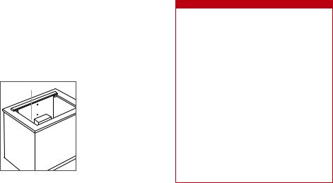
Important product information including the model and serial number are listed on the product rating plate. The rating plate is located next to the blower housing on the front side of the downdraft, below the countertop. Refer to the illustration below.
If service is necessary, contact Wolf factory certified service with the model and serial number.
RATING PLATE |
Rating plate location.
 WARNING
TO REDUCE THE RISK OF FIRE, ELECTRIC SHOCK, OR INJURY TO PERSONS, OBSERVE THE FOLLOWING:
a)Installation work and electrical wiring must be done by qualified person(s) in accordance with all applicable codes and standards, including fire-rated construction.
b)Sufficient air is needed for proper combustion and exhausting of gases through the flue (chimney) of fuel burning equipment to prevent back drafting. Follow the heating equipment manufacturer's guideline and safety standards, and the local code authorities.
c)When cutting or drilling into wall or ceiling, do not damage electrical wiring and other hidden utilities.
d)Ducted fans must always be vented to the outdoors.
2 | English

SPECIFICATIONS
Installation Requirements
For installation with a Wolf cooktop, a minimum 638 mm deep flat countertop is required.
For installation with a sealed burner rangetop, an accessory trim kit is required. Contact your authorized Wolf dealer for details.
The remote-mounted control module can be positioned horizontally or vertically. It must be located within 3 m of the downdraft assembly and a minimum 76 mm from the edge of the cooktop or rangetop cut-out.
BLOWERS
 CAUTION
For use with Wolf 1014 m3/hr internal blower and remote blowers rated maximum 3 amps.
Internal and remote blower assemblies are available through your authorized Wolf dealer.
Internal blowers include a 152 mm round discharge, can be front or rear mounted and can be discharged in any direction by rotating the blower box. Remote blowers have a 254 mm round discharge and can be discharged from the front or rear.
DUCTWORK
Wolf downdrafts must be vented outside.
Consult a qualified HVAC professional for specific installation and ducting applications.
The downdraft will operate most efficiently with the fewest number of elbows and transitions and when ductwork does not exceed 12 m.
Electrical
Installation must comply with all applicable electrical codes and be properly grounded (earthed).
Locate the electrical supply as shown in the illustrations on pages 3–4. A separate circuit, servicing only this appliance is required. A ground fault circuit interrupter (GFCI) is not recommended and may cause interruption of operation.
Certain installations may require that the electrical supply be placed in an adjacent cabinet.
ELECTRICAL REQUIREMENTS
DOWNDRAFTS |
|
Electrical Supply |
220-240 V AC, 50 Hz |
|
220 V AC, 60 Hz |
Service |
10 amp dedicated circuit |
Receptacle |
grounding-type (earthed) |
GROUNDING INSTRUCTIONS
This appliance must be grounded. In the event of an electrical short circuit, grounding reduces the risk of electric shock by providing an escape wire for the electric current. This appliance is equipped with a cord having a grounding wire with a grounding plug. The plug must be plugged into an outlet that is properly installed and grounded.
 WARNING
Improper grounding can result in a risk of electric shock. Consult a qualified electrician if the grounding instructions are not completely understood, or if doubt exists as to whether the appliance is properly grounded.
Do not use an extension cord. If the power supply cord is too short, have a qualified electrician install an outlet near the appliance.
Downdraft
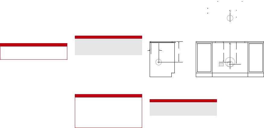
INSTALLATION WITH COOKTOP
|
W |
|
DOWNDRAFT |
|
CUT-OUT WIDTH |
68 mm |
E |
|
210 mm* |
|
COOKTOP CUT-OUT |
|
TOP VIEW |
210 |
540 |
mm* |
mm |
540 mm 594 mm
E
SIDE VIEW |
FRONT VIEW |
*152 mm back from countertop cut-out when internal blower is rear mounted.
NOTE: Internal blower 152 mm round, side, rear or bottom discharge. Remote blower 254 mm round, rear discharge. Centerline indicates center of downdraft cut-out.
CUT-OUT WIDTH
MODEL |
W |
ICBDD30 |
699 mm |
ICBDD36 |
851 mm |
ICBDD45 |
1003 mm |
wolfappliance.com | 3

SPECIFICATIONS
Downdraft
INSTALLATION WITH SEALED BURNER RANGETOP
W
DOWNDRAFT
CUT-OUT WIDTH
68 mm |
E |
|
210 mm* |
|
RANGETOP OPENING |
TOP VIEW
483 mm |
PLATFORM DEPTH |
540 |
mm |
210 |
mm* |
540 mm |
594 mm |
E |
|
SIDE VIEW |
FRONT VIEW |
*152 mm back from countertop cut-out when internal blower is rear mounted.
NOTE: Internal blower 152 mm round, side, rear or bottom discharge. Remote blower 254 mm round, rear discharge. Centerline indicates center of downdraft cut-out.
CUT-OUT WIDTH
MODEL |
W |
ICBDD30 |
699 mm |
INSTALLATION
Installation
DOWNDRAFT
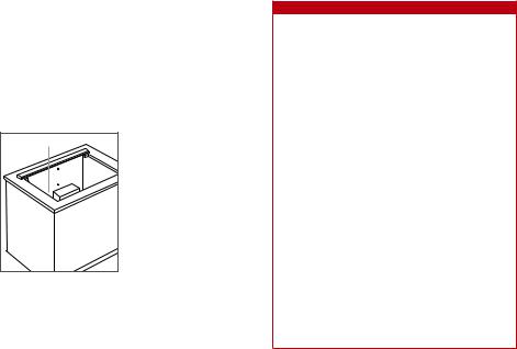
1Install the top mounting brackets using the #4 sheet metal screws provided. Refer to the illustration below.
2Install the lower mounting brackets using the #8 x 32 sheet metal screws provided, but do not tighten. The brackets will need to be adjusted once the downdraft is placed in the opening. Refer to the illustration below.
TRANSITION
For internal blowers, remove the existing 254 mm round transition. Refer to the illustration below.
For remote blowers being discharged from the front, leave the 254 mm round transition in place.
For remote blowers being discharged from the rear, remove the 254 mm round transition from the front and solid cover from the rear of the downdraft, then reinstall the 254 mm transition on the rear and solid cover on the front.
Top mounting bracket. |
Bottom leveling bracket. |
Remove transition.
4 | English

INSTALLATION
Installation
INTERNAL BLOWER
To mount the internal blower on the front or rear of the downdraft:
1Rotate the blower box so the 152 mm round discharge is properly located, then disconnect the cable from the
downdraft receptacle and connect it to the blower receptacle. Refer to the illustrations below.
2Once the blower connection is made and the discharge properly located, secure the blower to the downdraft using the four screws provided.
DISCHARGE |
DOWNDRAFT |
BLOWER |
RECEPTACLE |
RECEPTACLE |
Left, right or bottom discharge. Blower connection.
To mount the internal blower on the front of the downdraft but discharge from the rear:
1Remove the blower from the blower box.
2Mount the blower motor to the downdraft using the two screws provided.
3Remove the blower plug from the downdraft receptacle and insert it into the blower receptacle. Refer to the illustration below.
4Once the plug is installed and the blower secure, install the blower box to the downdraft using the four screws provided.
5Remove the 152 mm collar from the blower box and solid cover from the rear of the downdraft, then reinstall the 152 mm collar on the rear and solid cover on the blower box. Refer to the illustration below.
DOWNDRAFT |
COVER |
|
RECEPTACLE |
||
|
||
|
COLLAR |
|
|
BLOWER |
|
|
RECEPTACLE |
Blower mounting. |
Install cover. |
REMOTE BLOWER
1Insert the electrical supply from the remote blower through the opening on the downdraft and secure using an approved cord strain relief.
2Connect hot to brown, neutral to blue and ground to green. Refer to the illustration below.
HOT |
NEUTRAL |
GROUND |
|
POWER CORD |
|
RECEPTACLE |
|
WIRING |
BLUE |
COVER |
BROWN |
|
Wiring location. |
Remote blower wiring. |
COUNTERTOP MOUNTING
Place the downdraft in the opening, then secure the bottom brackets to the cabinet base using the wood screws provided. Once the brackets are secure, tighten the existing lower bracket screws. Refer to the illustration below.
Secure the top mounting brackets to the countertop using the wood screws provided. For solid surface countertops, silicone may be used but is not provided.
Once the top is secure, install the undercounter brackets using the screws provided then install the side covers. Refer to the illustration below.
 MOUNTING
SCREW
COVER
Countertop mounting. |
Cover installation. |
wolfappliance.com | 5
INSTALLATION
Installation
CONTROL MODULE
1Use the template provided on page 7 to mark holes for mounting screws. Drill one 40 mm in the center and two 10 mm holes for the mounting screws.
 CAUTION
Verify the scale of the template if not using the installation guide shipped with the downdraft.
2Check countertop thickness to make sure threaded studs are long enough to allow thumbnuts to fully engage. Thicker countertops may require the countertop be countersunk from below.
3Place the control module on the countertop then secure using the two nuts provided. Once secure, install the ground wire and nut.
4Use provided cable or cable designated by local codes. Connect one end of the control cable to back side of control module and other to electrical connection on front of downdraft assembly. Ensure all connections are tight.
 WARNING
Do not connect to telecommunication network.
TOP COVER
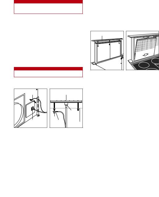
Insert the downdraft plug into a grounded (earthed) receptacle, then check operation. Once operation is verified, raise the chimney and install the top trim using the three nuts provided. Verify the top trim is properly aligned with the side covers. Refer to the illustration below.
FILTERS
Remove stickers and shipping brackets and install filters. Refer to the illustration below.
TOP COVER |
Top cover installation. |
Filter installation. |
Troubleshooting
IMPORTANT NOTE: If the downdraft ventilation system does not operate properly, follow these troubleshooting steps:
•Verify electrical power is supplied to the downdraft.
•Verify proper electrical connections.
•If the downdraft does not operate properly, contact Wolf factory certified service. Do not attempt to repair the downdraft. Wolf is not responsible for service required to correct a faulty installation.
GROUND |
CONTROL MODULE |
|
RJ45 |
|
CONNECTOR |
|
NUT |
RJ45 |
GROUND |
CONNECTOR |
COUNTERTOP |
Downdraft connection. |
Control module connection. |
6 | English
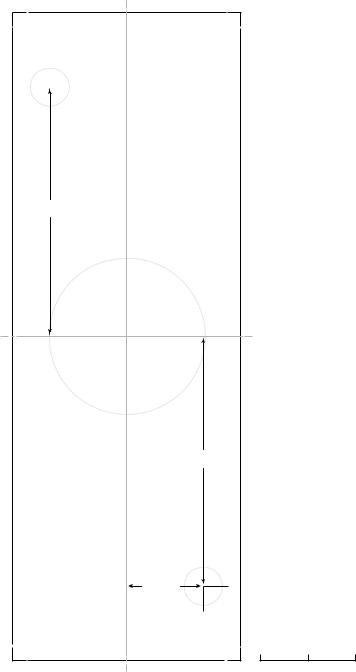
CONTROL MODULE TEMPLATE

 21 mm
21 mm 
65 mm
C
L
65 mm
21 mm |
|
0 |
25 mm |
C |
SCALE |
L |
|
Wolf, Wolf & Design, Wolf Gourmet, W & Design and the color red as applied to knobs are registered trademarks and service marks of Wolf Appliance, Inc. Sub-Zero, Sub-Zero & Design, Dual Refrigeration, Constant Care, The Living Kitchen, Great American Kitchens The Fine Art of Kitchen Design, and Ingredients are registered trademarks and service marks of Sub-Zero, Inc. (collectively, the “Company Marks.”) All other trademarks or registered trademarks are property of their respective owners in the United States and other countries.
wolfappliance.com | 7
CAMPANAS EXTRACTORAS DE ENCIMERA
Índice
2Ventilación de la campana extractora de encimera
3Especificaciones
4Instalación
6 Localización y solución de problemas
Las características y especificaciones están sujetas a cambios sin previo aviso. Visite wolfappliance.com/specs para obtener la información más actualizada.
Nota importante:
Para garantizar que este producto se instala y funciona de la forma más eficaz y segura posible, tenga en cuenta la información que se destaca en esta guía:
Cuando aparece NOTA IMPORTANTE, se resalta información que resulta especialmente importante.
PRECAUCIÓN indica una situación en la que se pueden sufrir heridas leves o provocar daños al producto si no se siguen las instrucciones.
AVISO indica el peligro de que se produzcan heridas graves o incluso la muerte si no se respetan las precauciones.
NOTA IMPORTANTE: conserve estas instrucciones para el inspector eléctrico local.
Información sobre el producto
En la placa de datos del producto encontrará información importante, incluyendo el modelo y el número de serie. La placa de datos se encuentra cerca del armazón del ventilador en la parte delantera de la campana extractora, debajo de la encimera. Consulte la siguiente ilustración.
Si necesita recurrir a un servicio técnico, póngase en contacto con un servicio de Wolf certificado con el modelo y el número de serie.
PLACA DE DATOS |
Ubicación de la placa de datos.
 AVISO
AVISO
PARA REDUCIR EL RIESGO DE INCENDIO, DESCARGA ELÉCTRICA O DAÑOS A PERSONAS, SIGA LAS SIGUIENTES INSTRUCCIONES:
a)La instalación de la campana y del cableado eléctrico deben ser realizadas por personal cualificado y deben hacerse siguiendo todos los códigos y normativas aplicables incluyendo los códigos y normativas contra incendios.
b)Es necesario que haya suficiente aire para que la combustión se lleve a cabo de manera correcta y para que la salida de gases se realice por el tubo de humos (chimenea)
del equipo de quemado de combustible y de ese modo evitar la retroventilación.
Siga las directrices y normas de seguridad del fabricante del equipo de cocción, y las normativas locales.
c)Cuando corte o taladre una pared o techo, tenga cuidado de no tocar las conexiones eléctricas ni otras utilidades ocultas que no se ven a simple vista.
d)Los ventiladores con tubo de salida deben tener siempre salida al exterior.
2 | Español
ESPECIFICACIONES
Requisitos de instalación
Para la instalación con una placa Wolf, es necesario dejar una profundidad mínima de encimera plana de 638 mm.
Para la instalación con una encimera de cocción con quemadores herméticos, se necesita un kit de marco para campana. Póngase en contacto con su distribuidor Wolf para obtener más información.
El módulo de control a distancia puede colocarse en posición horizontal o vertical. Debe situarse a 3 m de distancia de la campana y a 76 mm de distancia del borde del corte de la encimera de cocción a gas o de la placa.
VENTILADORES
 PRECAUCIÓN
Para su uso con el ventilador interno Wolf 1014 m3/hr y los ventiladores a distancia clasificados con un máximo de 3 amperios.
Los ventiladores internos y a distancia están disponibles a través de su distribuidor Wolf.
Los ventiladores internos incluyen una descarga redonda de 152 mm, pueden montarse en la parte delantera o en la trasera, y pueden descargarse en cualquier dirección girando la caja del ventilador. Los ventiladores a distancia poseen una descarga redonda de 254 mm y pueden descargarse desde la parte delantera o trasera.
TUBO
Las campanas extractores de encimera Wolf deben tener salida al exterior.
Póngase en contacto con un profesional especializado en calefacción, ventilación y aire acondicionado para obtener información específica sobre la instalación y canalización.
La campana extractora de encimera funcionará con más eficacia con el menor número de codos y transiciones posibles y cuando el tubo no supere los 12 m.
Potencia
La instalación debe cumplir con todas las normativas eléctricas aplicables y debe estar correctamente conectada a tierra.
Localice la toma eléctrica tal como se indica en las ilustraciones en las páginas 3-4. Se necesita un circuito independiente para esta unidad. No se recomienda utilizar un interruptor de circuito de fallos de toma de tierra (GFCI), ya que puede interrumpir el funcionamiento de la unidad.
Es posible que algunas instalaciones necesiten que la alimentación eléctrica esté situada en un armario cercano.
REQUISITOS ELÉCTRICOS
CAMPANAS EXTRACTORAS PARA ENCIMERA
Suministro eléctrico |
220-240 V AC, 50 Hz |
|
220 V AC, 60 Hz |
Servicio |
Circuito dedicado de 10 amperios |
Enchufe |
Con toma de tierra |
INSTRUCCIONES DE CONEXIÓN A TIERRA
Este aparato debe estar conectado a tierra de manera correcta. En caso de cortocircuito, la conexión a tierra reduce el riesgo de descarga eléctrica, ofreciendo un cable de escape para la corriente eléctrica. Este dispositivo
está equipado con un cable con conexión a tierra con un enchufe a tierra. El enchufe debe conectarse a una toma que esté correctamente instalada y conectada a tierra.
 AVISO
AVISO
Una conexión a tierra incorrecta puede suponer un riesgo de descarga eléctrica. Consulte a un electricista cualificado si no entiende bien las instrucciones de conexión a tierra, o si tiene dudas de si el dispositivo está correctamente conectado a tierra.
No utilice un cable alargador. Si el cable es demasiado corto, debe ser instalada una toma cerca del dispositivo por un electricista cualificado.
Campana extractora de encimera
INSTALACIÓN CON PLACA
|
|
|
|
|
|
|
|
|
Anch. |
|
|
|
|
|
||
|
|
|
|
|
|
|
|
|
|
|
||||||
|
|
|
|
|
|
|
|
|
W |
|
||||||
|
|
|
|
|
|
|
ANCHURA DE CORTE DE |
|
||||||||
|
|
|
|
|
|
|
|
DOWNDRAFT |
|
|||||||
|
|
|
|
|
LA CAMPANA EXTRACTORA |
|
||||||||||
|
|
|
|
|
|
|
CUT-OUT WIDTH |
|
||||||||
|
|
|
|
|
|
|
|
DE ENCIMERA |
|
|||||||
|
68 mm |
|
|
|
E |
|
mm* |
|
|
|||||||
|
|
|
|
|
|
|
|
|
|
210 |
|
|
||||
|
|
|
|
|
|
|
||||||||||
|
|
|
|
|
|
|
|
|
|
|
|
|
|
|||
|
|
|
|
|
|
|
|
|
|
|
|
|
|
|
|
|
|
|
|
|
|
|
CORTE DE LA SUPERFICIE |
|
|||||||||
|
|
|
|
|
|
|
COOKTOP CUT-OUT |
|
||||||||
|
|
|
|
|
|
|
|
DE COCCIÓN |
|
|||||||
|
|
|
|
|
|
|
|
|
|
|
|
|
|
|
|
|
|
|
|
|
|
|
|
|
|
|
|
|
|
|
|
|
|
|
|
|
|
|
|
|
|
|
SUPERIOR |
|
||||||
|
|
|
|
|
|
|
VISTAOP VIEW |
|
||||||||
210 |
540 |
mm* |
mm |
VISTASIDE VIEWLATERAL |
|
540 mm 594 mm
E
VISTAFRONTFRONTALVIEW
*152152mmdesdeback fromel cortecountdertopla encimera,cut-out whencuandointernalel ventiladorblower isinternorear mountedse instala. en montaje posterior.
NOTA:NOTE:ventiladorInternal blowerinterno152demm152round,mm deside,descargarear orredonda,bottom dischargelateral, trasera. Remoteinferiorblower. Ventilador254 mm round,a distanciarear dischargede 254 mm. de descarga redonda, trasera. LaCenterlinlínea centralindicatesindicacenteel centroof downdraftdel cortecutde-laoutcampana. extractora de encimera.
ANCHURA DEL CORTE
MODELO |
Anch. |
ICBDD30 |
699 mm |
ICBDD36 |
851 mm |
ICBDD45 |
1003 mm |
wolfappliance.com | 3

ESPECIFICACIONES
Campana extractora de encimera
INSTALACIÓN CON ENCIMERA DE COCCIÓN A GAS CON QUEMADORES HERMÉTICOS
483 mm |
PROFUNDIDAD |
PLATFORM DEPTH |
LA PLATAFORMA |
540 |
mm |
210 |
mm* |
VISTASIDE VIEWLATERAL
AnchW .
ANCHURADOWNDRAFTDE CORTE DE
LA CAMPANA EXTRACTORA
CUT-OUT WIDTH
DE ENCIMERA
68 mm |
E |
|
210 mm* |
|
CAVIDAD DE LA ENCIMERA |
|
RANGETOP OPENING |
|
DE COCCIÓN |
VISTAOPSUPERIORVIEW
540 mm |
594 mm |
E |
|
VISTAFRONTFRONTALVIEW
*152152mm desdeback fromel cortecountdertopla encimera,cut-out whencuandointernalel ventiladorblower isinternorear mountedse instala. en montaje posterior.
NOTA:NOTE:ventiladorInternal blowerinterno152demm152round,mm deside,descargaea orredonda,bottom dischargelateral, trasera. Remoteinferiorblower. Ventilador254 mm round,a distanciarear dischargede 254 mm. de descarga redonda, trasera. LaCenterlinlínea centralindicatesindicacenteel centroof downdraftdel cortecutde-laoutcampana. extractora de encimera.
ANCHURA DEL CORTE
MODELO |
Anch. |
ICBDD30 |
699 mm |
INSTALACIÓN
Instalación
CAMPANAS EXTRACTORAS DE ENCIMERA
1Instale los soportes de montaje superiores utilizando los tornillos de metal #4 suministrados. Consulte la siguiente ilustración.
2Instale los soportes de montaje inferiores utilizando los 32 tornillos de metal de #8 suministrados, pero no los apriete. Los soportes necesitarán ajustarse cuando la campana extractora de encimera está colocada en la cavidad. Consulte la siguiente ilustración.
Soporte de montaje superior. |
Soporte de montaje inferior. |
TRANSICIÓN
Para los ventiladores internos, extraiga la transición redonda de 254 mm existente. Consulte la siguiente ilustración.
Para ventiladores a distancia con descarga desde la parte delantera, deje una transición redonda de 254 mm.
Para los ventiladores a distancia con descarga desde la parte posterior, extraiga la transición redonda de 254 mm de la parte delantera y la cubierta sólida de la parte posterior de la campana extractora, y luego vuelva a instalar la transición de 254 mm en la parte trasera, y la cubierta sólida en la delantera.
Extraer transición.
4 | Español
 Loading...