


Pup IV
PARTS
AND
SERVICE
MANUAL
PUP
··1v··
PUP
··y··
INSTALLATION
•
OPERATING
MAINTENANCE
INSTRUCTIONS
AND
PARTS
LIST
Reprint September 2008
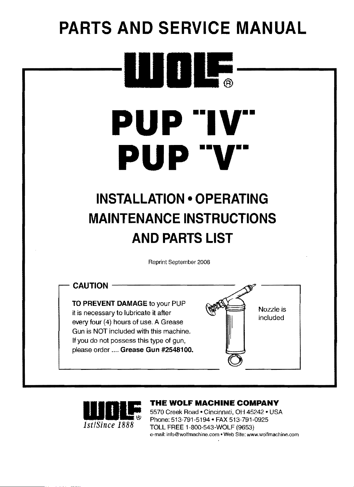
TO
PREVENT
DAMAGE
to
your
PUP
it
is necessary
to
lubricate
it
after
every four
(4)
hours
of
use. A Grease
Gun is
NOT
included
with
this machine.
If you
do
not possess this type
of
gun,
please order ....
Grease
Gun
#2548100.
Nozzle
is
included
1111!
1st/Since
1888
THE
WOLF
MACHINE
COMPANY
5570 Creek Road • Cincinnati, OH 45242 • USA
Phone: 513-791-5194 • FAX 513-791-0925
TOLL FREE 1-800-543-WOLF (9653)
e~mail:
info@wolfmachine.com
•Web
Site: www.wolfmachine.com
From the library of: Superior Sewing Machine & Supply LLC
WOLF
PUP
··1v· &
·y·
MAINTENANCE & OPERATING INSTRUCTIONS
WARNING
This
is
a hazardous type
of
machinery
and
should be used with care. Always disconnect electrical
or
air connector before performing repairs, adjustments
or
maintenance. Be sure all electrical machines
are properly grounded. Never
allow any
part
of
your person
or
any other person
to
be
in the path
of
the
blade when the machine
Is
in
service. Only grip machine by the handles provided. For personal safety
the operator should remove
all
loose fitting jewelry,
shouldn't
wear loose or baggy fitting clothing and
persons with
long hair should cover
or
pull
it
back.
LUBRICATION
It is
necessary
to
lubricate
the
gears
of
the
PUP
and
aho
the
backside
of the
blade.
To
lubricate
blade,
apply
oi~
through
the
hole
in
side
of the
cutting
head.
To
grease
knife
gear
1
apply
grease
through
the
fitting
provided
ot
the
front
of
the
cutting
head. KNIFE
GEAR
SHOUI.D
BE
GREASED
AFTER
EVERY
FOUR
HOURS
OF
USE
TO
INSURE
PROPER
LIFE
OF
THE
GEAR.
TO
MAINTAIN
BEST
CUTTING
PERFORMANCE
To
maintain
top
performance,
replace
the
knife
on
the
PUP
machine
as
the
knife
starts to
become
round
and
the
blades
1
corners
begin
to
we or
away.
The PUP wi
II
cut
best
when
the
comers
of
the
knife
ore
maintained
o:;
definite
angles
with
little
or
no
rounding.
When
the
knife
ls used
with
a
worn
blade,
the
cutting
edge
will
make
contoct
further
back
on
the
corbide
insert
in
the
shoe
and
stort
uneven
wear.
This causes a loss of
the
scissor
action
and
almost
oil
cutting
power
is
lost.
TO
REMOVE AND REPLACE BLADE
To remove
blade
1
toke
out
the
grinder
brocket
screw
that
holds
the
brocket
to
the
head.
After
grinder
brocket
is
re-
moved,
use
the
pin
wrench,
supp[ied
with
the
machine,
ond
remove
the
knife
lock
nut.
The
knife
con
then
be
removed.
Before
replacing
the
grinder
housing,
be sure
that
the
grind-
ing
wheel
is
clean.
When
grinding
wheel
is
worn,
replace
it.
This will
save
knife
blade
replacement
and
keep
cutting
ot
top
performance.
TO REPLACE
GRINDING
WHEEL
Remove
grinder
housing from
machine,
then
loosen
set
screw
in
grinder
knob
and
remove from
shaft.
Next
remove
#J2l6l93-
snap
ring from end
of
wheel
shah
one
toke
off
worn
out
grinding
whee
I,
lubricate
shaft
on
new
wheelr
then
replace
snap
ring
and
knob in
grinder
housing.
Check
to
make
sure
wheel
rotates
freely.
Remount
grinder
housing
to
head.
Sharpen
knife
to o
good
keen
edge
on
the
corl"'ers
orly
_
If
any
additlonat
repairs or problems
are
encourtered,
it
would
be
advisable
to
return
the
machine
to
the
factory
for repoi rs.
For
best
results usc
only
genuine
Wolf
knife
blades
and
ports.
TO
USE
WITHOUT FOOTPLATE
For more
intricate
types
of
trimming
it
may be
desir0blc
to
use
the
machine
without
the small
Jootplate
provid~?:d.
ln
order
to
remove
this
footplote,
use small
wrench
to
loosen
screws
at
the
side
of
the
plate,
Keep
knife
properly
ad-
justed
ond
sharp
for
best
results in
cutting.
ELECTRIC
MODEL-MAINTENANCE
and OPERATION
Operator
should
\.•:>e
core
in
operating
the
machine
ond
not
cover
the
oir
exhaust
hales
of
the
motor
wHh
fingen
while
using
the
machine.
If
this
is
done
it
will
cause
the
nn:'Jchine
to
get
excessively
hot
ond
may
burn
out
the
motor.
The
air
inlet
holes
should
be
kept
clear
of
lint
at
alf
ttmes
so
that
air
can
get
in
to
cool
the
motor
while
running,
DISASSEMBLY OF
MOTOR
For
replacement
of
brushes,
switch
or
line
wire-
Disassemble
by
removing
the
3
small
scre\1'1$
arounci
tf«:.!
out-
side
at
the
front
of
the
motor.
This
will
allow
the
motor
case
to
be
slipped
bock,
off
the
motor.
Caution
shcvld
be
taken
when
removing
this,
so os
nat
to
force
or
put
tCP!
much
pressure
on
the
wires.
Also
see
that
wires
are
in
proper
po-
sition
when
replacing
case.
When
replacing
outer
hc<1singr
be
sure
that
vent
holes
ore
open
ond
not
covered
so
thot
the
exhaust
olr
can
blow
freely
from
motor.
AIR MODEL
INSTALLATION
For
top
performonce
1
90
fbs. of
air
9fe~sure
(10
cubic
feet
per
minute)
should
be
supplied
for
each
machine
in
contin-
uous
operation.
A
filter
lJbricotor
ond
regulator
is
recom-
mended.
These
ore
available
from The
Vv'o!f
Machine
Co,
for
all
Air
Model
PUP
instal
lotions.
Air
han91e
position
moy
be
rotated
os
desired.
Loosen
the
two
screws
(#9900
123)
that
hold
front
heod
1
then
rotate
to
desired
position
and
retighten.
From the library of: Superior Sewing Machine & Supply LLC
 Loading...