


 Loading...
Installation, Operation,
and Maintenance
Split System Air Conditioners
Odyssey™ ™
R-22 Dry Charge
Heat Pump Condenser — 7.5, 10, 15 and 20 Tons
(60 Hz)
TWA090A***G*
TWA120A***G*
TWA180B***G*
TWA240B***G*
 SAFETY WARNING
Only qualified personnel should install and service the equipment. The installation, starting up, and servicing of heating, ventilating, and air-conditioning equipment can be hazardous and requires specific knowledge and training. Improperly installed, adjusted or altered equipment by an unqualified person could result in death or serious injury. When working on the equipment, observe all precautions in the literature and on the tags, stickers, and labels that are attached to the equipment.
January 2014 |
SSP-SVX15C-EN |
Introduction
Read this manual thoroughly before operating or servicing this unit.
Warnings, Cautions, and Notices
Safety advisories appear throughout this manual as required. Your personal safety and the proper operation of this machine depend upon the strict observance of these precautions.
The three types of advisories are defined as follows:
Indicates a potentially hazardous situation which, if not avoided, could result in death or serious injury.
Indicates a potentially hazardous situation which, if not avoided, could result in minor or moderate injury. It could also be used to alert against unsafe practices.
Indicates a situation that could result in equipment or property-damage only accidents.
Important Environmental Concerns
Scientific research has shown that certain man-made chemicals can affect the earth’s naturally occurring stratospheric ozone layer when released to the atmosphere. In particular, several of the identified chemicals that may affect the ozone layer are refrigerants that contain Chlorine, Fluorine and Carbon (CFCs) and those containing Hydrogen, Chlorine, Fluorine and Carbon (HCFCs). Not all refrigerants containing these compounds have the same potential impact to the environment. Trane advocates the responsible handling of all refrigerants-including industry replacements for CFCs such as HCFCs and HFCs.
Important Responsible Refrigerant
Practices
Trane believes that responsible refrigerant practices are important to the environment, our customers, and the air conditioning industry. All technicians who handle refrigerants must be certified. The Federal Clean Air Act (Section 608) sets forth the requirements for handling, reclaiming, recovering and recycling of certain refrigerants and the equipment that is used in these service procedures. In addition, some states or municipalities may have additional requirements that must also be adhered to for responsible management of refrigerants. Know the applicable laws and follow them.
 WARNING
Proper Field Wiring and Grounding Required!
Failure to follow code could result in death or serious injury.
All field wiring MUST be performed by qualified personnel. Improperly installed and grounded field wiring poses FIRE and ELECTROCUTION hazards. To avoid these hazards, you MUST follow requirements for field wiring installation and grounding as described in NEC and your local/ state electrical codes.
 WARNING
Personal Protective Equipment (PPE)
Required!
Failure to wear proper PPE for the job being undertaken could result in death or serious injury. Technicians, in order to protect themselves from potential electrical, mechanical, and chemical hazards, MUST follow precautions in this manual and on the tags, stickers, and labels, as well as the instructions below:
•Before installing/servicing this unit, technicians MUST put on all Personal Protective Equipment (PPE) recommended for the work being undertaken. ALWAYS refer to appropriate MSDS sheets and OSHA guidelines for proper PPE.
•When working with or around hazardous chemicals, ALWAYS refer to the appropriate MSDS sheets and OSHA guidelines for information on allowable personal exposure levels, proper respiratory protection and handling recommendations.
•If there is a risk of arc or flash, technicians MUST put on all Personal Protective Equipment (PPE) in accordance with NFPA 70E or other country-specific requirements for arc flash protection, PRIOR to servicing the unit.
©2014 Trane All rights reserved |
SSP-SVX15C-EN |

 WARNING
Refrigerant under High Pressure!
Failure to follow instructions below could result in an explosion which could result in death or serious injury or equipment damage.
System contains oil and refrigerant under high pressure. Recover refrigerant to relieve pressure before opening the system. See unit nameplate for refrigerant type. Do not use non-approved refrigerants, refrigerant substitutes, or refrigerant additives.
Copyright
This document and the information in it are the property of Trane and may not be used or reproduced
Introduction
in whole or in part, without the written permission of Trane. Trane reserves the right to revise this publication at any time and to make changes to its content without obligation to notify any person of such revision or change.
Trademarks
All trademarks referenced in this document are the trademarks of their respective owners.
Revision History
Removed warranty chapter, updated with running edits.
SSP-SVX15C-EN |
3 |
Table of Contents
Model Number Description . . . . . . . . . . . . . . . . . 6
Heat Pump Condenser . . . . . . . . . . . . . . . . . . . . 6
General Information . . . . . . . . . . . . . . . . . . . . . . . . 7
Unit Description . . . . . . . . . . . . . . . . . . . . . . . . . . 7
Pre-Installation . . . . . . . . . . . . . . . . . . . . . . . . . . . . . 8
Unit Inspection . . . . . . . . . . . . . . . . . . . . . . . . . . . 8
Inspection Checklist . . . . . . . . . . . . . . . . . . . 8
Testing for Leaks. . . . . . . . . . . . . . . . . . . . . . . . . . 8
Lifting Recommendations . . . . . . . . . . . . . . . . . 8
Clearances . . . . . . . . . . . . . . . . . . . . . . . . . . . . . . . 8
Unit Mounting. . . . . . . . . . . . . . . . . . . . . . . . . . . . 9
Structural Preparation . . . . . . . . . . . . . . . . . 9
Rooftop Mounting . . . . . . . . . . . . . . . . . . . . 9
Ground Level Mounting . . . . . . . . . . . . . . . 9
Snow Belt Recommendations . . . . . . . . . . . . . 9
Dimensional Data . . . . . . . . . . . . . . . . . . . . . . . . . 10
Weights . . . . . . . . . . . . . . . . . . . . . . . . . . . . . . . . . . . 14
Heat Pump Condenser . . . . . . . . . . . . . . . . . . . 14
Installation . . . . . . . . . . . . . . . . . . . . . . . . . . . . . . . . 15
Refrigerant Piping Guidelines. . . . . . . . . . . . . 15
Refrigerant Piping Procedures (Outdoor
Units). . . . . . . . . . . . . . . . . . . . . . . . . . . . . . . . . . . 16
Refrigerant Piping Procedures (Indoor
Unit). . . . . . . . . . . . . . . . . . . . . . . . . . . . . . . . . . . . 17
Leak Check . . . . . . . . . . . . . . . . . . . . . . . . . . . . . . 17
System Evacuation. . . . . . . . . . . . . . . . . . . 17
Insulating and Isolating Refrigerant
Lines . . . . . . . . . . . . . . . . . . . . . . . . . . . . . . . . . . . 18
Refrigerant Charging Procedure . . . . . . . . . . 18
Liquid Charging . . . . . . . . . . . . . . . . . . . . . . . . . 19
Electrical Wiring . . . . . . . . . . . . . . . . . . . . . . . . . 19
Unit Power Supply . . . . . . . . . . . . . . . . . . . 20
Low Voltage Wiring . . . . . . . . . . . . . . . . . . 20
ReliaTel Controls . . . . .™. . . . . . . . . . . . . . 20
Field Wiring . . . . . . . . . . . . . . . . . . . . . . . . . 21
Refrigerant Circuit. . . . . . . . . . . . . . . . . . . . 22
Electrical Data . . . . . . . . . . . . . . . . . . . . . . . . . . . . . 24
Charging Charts and Superheat . . . . . . . . . . . 25
Installation Checklist. . . . . . . . . . . . . . . . . . . . . . . 26
Refrigerant Piping . . . . . . . . . . . . . . . . . . . . . . . 26
Electrical Wiring . . . . . . . . . . . . . . . . . . . . . . . . . 26
Pre-Start . . . . . . . . . . . . . . . . . . . . . . . . . . . . . . . . . . . 27
Control Circuit Features . . . . . . . . . . . . . . . . . . 27 Discharge Temperature Limit
(DTL). . . . . . . . . . . . . . . . . . . . . . . . . . . . . . . . 27 Evaporator Defrost Control
(EDC) . . . . . . . . . . . . . . . . . . . . . . . . . . . . . . . 27 Low Pressure Cut-Out (LPCO) . . . . . . . . . 27 High Pressure Cut-Out (HPCO) . . . . . . . . 27 Internal Overload Protector
(IOL) . . . . . . . . . . . . . . . . . . . . . . . . . . . . . . . . 27
Start-Up . . . . . . . . . . . . . . . . . . . . . . . . . . . . . . . . . . . 28
ReliaTel Controls . . . |
.™. . . . . . . . . . . . . . . . . . |
28 |
Terminology . . . . . . . |
. . . . . . . . . . . . . . . . . . |
28 |
Functions and Features . . . . . . . . . . . . . . . |
28 |
|
Service Test Modes for ReliaTel |
™ |
|
Controls . . . . . . . . . . . . . . . . . |
. . . . . . . . . . . . . . . . . . |
33 |
Test Modes. . . . . . . . . . . . . . . . . . . . . . . . . . . . . . 33
Step Test Mode . . . . . . . . . . . . . . . . . . . . . . 33
Resistance Test Mode . . . . . . . . . . . . . . . . 33
Auto Test Mode . . . . . . . . . . . . . . . . . . . . . . 33
Troubleshooting . . . . . . . . . . . . . . . . . . . . . . . . . . . 34
Troubleshooting ReliaTel™ Controls. . . . . . . 34
System Status Checkout Procedure . . . . . . . 34
Method 1 . . . . . . . . . . . . . . . . . . . . . . . . . . . . 34
Method 2 . . . . . . . . . . . . . . . . . . . . . . . . . . . . 35
Resetting Cooling and Heating
Lockouts . . . . . . . . . . . . . . . . . . . . . . . . . . . . . . . . 35
Method 1 . . . . . . . . . . . . . . . . . . . . . . . . . . . . 35
Method 2 . . . . . . . . . . . . . . . . . . . . . . . . . . . . 35
Zone Temperature Sensor (ZTS) Service
Indicator . . . . . . . . . . . . . . . . . . . . . . . . . . . . . . . . 35
Temperature Tests . . . . . . . . . . . . . . . . . . . . . . . 36
Test 1 - Zone Temperature
Thermistor (ZTEMP). . . . . . . . . . . . . . . . . . 36
Test 2 - Cooling Set Point (CSP) and
Heating Set Point (HSP). . . . . . . . . . . . . . . 36
Test 3 - System Mode and Fan
Selection . . . . . . . . . . . . . . . . . . . . . . . . . . . . 36
Test 4 - LED Indicator Test (SYS ON,
HEAT, & COOL). . . . . . . . . . . . . . . . . . . . . . . 37
Programmable & Digital Zone Sensor
Test. . . . . . . . . . . . . . . . . . . . . . . . . . . . . . . . . . . . . 37
Testing Serial Communication
Voltage. . . . . . . . . . . . . . . . . . . . . . . . . . . . . . 37
RLCI Loss of Communications. . . . . . . . . 37
Maintenance . . . . . . . . . . . . . . . . . . . . . . . . . . . . . . 38
Monthly . . . . . . . . . . . . . . . . . . . . . . . . . . . . . . . . 38
Annually (Cooling Season) . . . . . . . . . . . . . . . 38
Coil Cleaning . . . . . . . . . . . . . . . . . . . . . . . . . . . . 38
4 |
SSP-SVX15C-EN |

Table of Contents
Maintenance Log . . . . . . . . . . . . . . . . . . . . . . . . |
39 |
Charging Charts and Superheat . . . . . . . . . . . . . . |
Wiring Diagram Matrix |
40 |
Dimensional Data. . . . . . . . . . . . . . . . . . . . . . . . . . . |
|
Charging Charts and Superheat |
Charging Charts and Superheat . . . . . . . . . . . . . . |
|
SSP-SVX15C-EN |
5 |

Model Number Description
Heat Pump Condenser
T W A |
120 |
A |
3 |
1 2 3 |
4 5 6 |
7 |
8 |
All products are identified by a multiple-character model number that precisely identifies a particular type of unit. An explanation of the alphanumeric identification code is provided. Its use will enable the owner/operator, installing contractors, and service engineers to define the operation, specific components, and other options for any specific unit. When ordering replacement parts or requesting service, be sure to refer to the specific model number, serial number, and DL number (if applicable) stamped on the unit nameplate.
DIGITS 1 - 3: Product Type
TWA = Split System Heat Pump
DIGITS 4 - 6: Nominal Gross Cooling Capacity (MBh)
090 = 7.5 Tons (60Hz)
120 = 10 Tons (60Hz)
0 0 |
* |
* |
9 10 |
11 |
12 |
180 = 15 Tons (60Hz)
240 = 20 Tons (60Hz)
DIGIT 7: Major Development Sequence
A = Single Compressor, Single Circuit, R-22 B = Dual Compressor, Dual Circuit, R-22
DIGIT 8: Electrical Characteristics
3 = 208–230/60/3
4 = 460/60/3
DIGITS 9 - 10: Factory Installed Options
00 = Packed Stock
DIGITS 11: Minor Design Sequence
* = Current Design Sequence1
DIGITS 12: Service Digit
* = Current Design Sequence1
1. * = sequential alpha character
6 |
SSP-SVX15C-EN |
General Information
This manual describes proper installation, operation, and maintenance procedures for air-cooled systems. By carefully reviewing the information within this manual and following the instructions, the risk of improper operation and/or component damage will be minimized. It is important that periodic maintenance be performed to help assure trouble free operation. Should equipment failure occur, contact a qualified service organization with qualified, experienced HVAC technicians to properly diagnose and repair this equipment.
Important: All phases of this installation must comply with the NATIONAL, STATE & LOCAL CODES. In addition to local codes, the installation must conform with National Electric Code -ANSI/NFPA NO. 70 LATEST REVISION.
Any individual installing, maintaining, or servicing this equipment must be properly trained, licensed and qualified.
Important: Do not remove the VFD without first contacting technical support! For performance-related questions and diagnostic support in North America call 1- 877-872-6363. Any return requires a claim number FIRST. Removal of the VFD prior to this step will void the unit’s warranties.
Installation procedures should be performed in the sequence that they appear in this manual. Do not destroy or remove the manual from the unit. The
manual should remain weather-protected with the unit until all installation procedures are complete.
Note: It is not the intention of this manual to cover all possible variations in systems that may occur or to provide comprehensive information concerning every possible contingency that may be encountered during an installation. If additional information is required or if specific problems arise that are not fully discussed in this manual, contact your local sales office.
Use the ”Installation Checklist,” p. 26 provided In this manual to verify that all necessary installation procedures have been completed. Do not use the checklist as a substitute for reading the information contained in the manual. Read the entire manual before beginning installation procedures.
Unit Description
These condensers come with single and dual compressor options. Single compressor outdoor units feature a single refrigeration circuitry, requiring only one set of refrigerant lines. Dual compressor/dual circuit models give true stand-by protection; if one compressor fails, the second will automatically startup. Also, the first compressor can be serviced without shutting down the unit since the refrigerant circuits are independent. During light load conditions, only one compressor will operate to save energy.
SSP-SVX15C-EN |
7 |
Pre-Installation
Unit Inspection
Inspect material carefully for any shipping damage. If damaged, it must be reported to, and claims made against the transportation company. Compare the information that appears on the unit nameplate with ordering and submittal data to ensure the proper unit was shipped. Available power supply must be compatible with electrical characteristics specified on component nameplates. Replace damaged parts with authorized parts only.
Inspection Checklist
To protect against loss due to damage incurred in transit, complete the following checklist upon receipt of the unit.
Inspect individual pieces of the shipment before accepting the unit. Check for obvious damage to the unit or packing material.
Inspect the unit for concealed damage before it is stored and as soon as possible after delivery. Concealed damage must be reported within 15 days. If concealed damage is discovered, stop unpacking the shipment. Do not remove damaged material from the receiving location. Take photos of the damage if possible. The owner must provide reasonable evidence that the damage did not occur after delivery.
Notify the carrier’s terminal of damage immediately by phone and by mail. Request an immediate joint inspection of the damage by the carrier and the consignee.
Notify the sales representative and arrange for repair. Do not repair the unit until the damage is inspected by the carrier’s representative.
Testing for Leaks
All units are shipped with a holding charge of nitrogen in each circuit and should be leak tested before installation.
1.Remove the access panel.
2.Locate the liquid line or suction line access valve for each circuit.
3.Install gauges to determine if the circuits are still pressurized. If not, the charge has escaped and should be repaired as required to obtain a leak-free circuit.
Lifting Recommendations
 WARNING
Improper Unit Lift!
Failure to properly lift unit could result in unit dropping and possibly crushing operator/ technician which could result in death or serious injury, and equipment or property-only damage. Test lift unit approximately 24 inches to verify proper center of gravity lift point. To avoid dropping of unit, reposition lifting point if unit is not level.
NOTICE
Equipment Damage!
Use spreader bars to prevent straps from damaging the unit. Install the bars between lifting straps, both underneath the unit and above the unit to prevent the straps from crushing the unit cabinet or damaging the finish.
Before preparing the unit for lifting, estimate the approximate center of gravity for lifting safety. Because of placement of internal components, the unit weight may be unevenly distributed. See ”Weights”, p. 14 for approximate unit weights.
The crated unit can be moved using a forklift of suitable capacity. For lifting the unit, attach lifting straps or slings securely to the lifting holes at each corner (see unit drawings in ”Weights”, p. 14 Use spreader). bars to protect the unit casing from damage. Test lift the unit to determine proper balance and stability.
Clearances
Provide enough space around the unit to allow unrestricted access to all service points. Refer to the ”Dimensional Data,” p. 10 for unit dimensions and minimum required service and free air clearances. Observe the following points to ensure proper unit operation.
1.Do not install the unit under a low overhang. Condenser discharge must not be restricted—refer
to notes in ”Dimensional Data drawings,” p. 10 |
. |
Important: Do not obstruct condenser discharge air. This can result in warm air recirculation through the coil.
2.Do not locate the unit in a position where runoff water can fall into the fan discharge openings.
3.Condenser intake air is supplied from three or four sides of the unit. Adhere to the minimum required clearances given in unit dimensional drawings (see ”Dimensional Data,” p. 10).
8 |
SSP-SVX15C-EN |

Unit Mounting
 WARNING
Mounting Integrity!
Failure to follow instruction below could result in death or serious injury or possible equipment or property-only damage.
Ensure the roof structure supports are strong enough to support the weight of the unit and any accessories.
Structural Preparation
NOTICE
Roof Damage!
System contains oil and refrigerant under high pressure. Roofs should be protected from exposure to oils and refrigerant in the system. If rooftop is not protected, damage to the roof may occur.
Important: Refer to local building codes for proper installation. All installation must comply with local building codes.
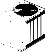
Rooftop Mounting
If the unit will be roof mounted, determine for certain that the structure is strong enough to support the unit
and any required accessories, see ”Weights”, p. 14 The . unit should be elevated on a level, field fabricated four-
inch steel or wood 4" x 4" mounting frame. Complete the frame and secure it into position before lifting the unit to the roof. The mounting frame must support a minimum of three of the unit’s four sides and should span roof supports to distribute the load on the roof.
Figure 1. Roof mounted unit
Pre-Installation
Ground Level Mounting
For ground level installation, the unit base should be adequately supported and hold the unit near level. The installation must meet the guidelines set forth in local codes. The support should extend two inches beyond the unit base channels at all points. The unit and support must be isolated from any adjacent structure to prevent possible noise or vibration problems. Any ground level location must comply with required clearances given in the unit dimensional drawings (see ”Dimensional Data,” p. 10 ).
Snow Belt Recommendations
In regions where deep snow is encountered, raise the unit a minimum distance of 8 to 12 inches above the mounting surface. This will reduce the risk of snow blocking the coil and improves runoff of water produced during the defrost cycle. Avoid locating the unit where snow tends to drift. Snow accumulations must be removed from around the unit immediately to prevent drastic efficiency reduction. A snow drift barrier may be constructed around the unit to prevent snow blockage. Clearance between the snow barrier and the unit must comply with the clearances given in ”Dimensional Data drawings,” p. 10 .
SSP-SVX15C-EN |
9 |
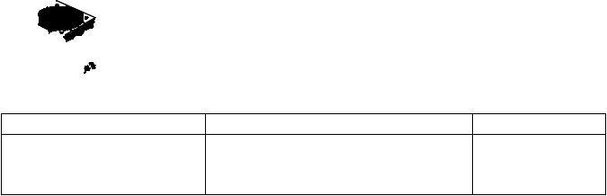
Dimensional Data
Figure 2. Height, width and depth measurements
|
H |
|
|
|
H |
|
|
|
|
|
|
W |
|
|
|
W |
D |
|
|
D |
|
|
|
|
|
|
H - in. (mm) |
W - in. (mm) |
D - in. (mm) |
|
TWA090A |
39.125 (993.8) |
42.125 (1070) |
36 (914.4) |
|
TWA120A |
39.125 (993.8) |
52.125 (1324) |
40 (1016) |
|
TWA180B, TWA240B |
45.125 (1146.1) |
52.125 (1324) |
40 (1016) |
10 |
SSP-SVX15C-EN |
Dimensional Data
Figure 3. 7.5 ton heat pump, single compressor
SEE NOTE 3
SERVICE PANEL
SEE NOTE 4
|
S ERVICE CLEARANCE |
|
48" (1219.2) (S EE NOTE 2 |
|
FOR CLEARANCE) |
HAIL GUARD |
|
(OP TIONAL) |
LINE VOLTAGE |
|
CONT ROL WIRING |
|
|
36 3/8" |
|
|
(923.9) |
|
|
29 13/16" |
|
|
(757.2) |
|
5 5/8" |
8 5/16" |
|
(211.1) |
||
(143) |
||
|
1/16"
(1.6)
LIQUID LINE
SUCTION LINE
3" (76. 2)
34 3/4"
40 3/4" (882.7)
(1035)
4 3/16"
(106.4)
1 13/16"
(46)
NOTES :
1. ACCES S OP ENING IS FOR FIELD INS TALLED BAYLOAM ACCES S ORY. 2. MINIMUM CLEARANCE FOR P ROP ER OP ERATION IS 36" ( 914.4) FROM
WALLS , S HRUBBERY, P RIVACY FENCES ETC. MINIMUM CLEARANCE B ETWEEN ADJ ACENT UNITS IS 72" (1828.8). RECOMMENDED S ERVICE C LEARANCE 48" (1219.2)
3. TOP DIS CHARGE AREA S HOULD BE UNRES TRICTED FOR 100" (2540) MINIMUM. UNIT S HOULD BE P LACED S O ROOF RUN-OFF WATER DOES NOT P OUR DIRECTLY ON UNIT
4. OUTDOOR AIR TEMP ERATURE S ENS OR OP ENING (DO NOT BLOCK OP ENING)
HAIL GUARD (OP TIONAL)
35 15 /16" |
|
(912.8 ) |
S EE NOTE 1 |
WITH HAIL GUARD |
|
33 15 /16" |
|
(86 2) |
REFRIGERANT ACCES S |
|
|
39 3/16" |
|
SER VICE P ANEL |
|
(995.4) |
|
|
|
26 15/16" |
|
|
|
(684.2) |
|
|
|
14 3/8" |
|
|
|
(365.1) |
|
|
6" |
3 1/16" (77.8) |
|
6" |
(152 .4) |
||
|
|||
(152 .4) |
|
2" (50.8) |
|
21 11 /16" |
|
||
|
41 1/16" |
||
(55 0.9) |
|
||
|
(1043) |
||
33 13/1 6" |
|
||
|
42 1/8" |
||
(858 .8) |
|
||
|
|
(1070) |
WITH HAIL GUARD
SERVIC E P ANEL S IDE
7/16" (11.1) DIA. IS OLATOR MOUNTING HOLES (OUTS IDE HOLES - 4 P LACES )
BOTTOM
OF UNIT
27 11/ 16" |
2 5/16" |
(703.3 ) |
(58.7) |
SSP-SVX15C-EN |
11 |
Dimensional Data
Figure 4. 10 ton heat pump, single compressor
SEE NOTE 3
SERVICE PANEL
SEE NOTE 4
NOTES :
1. ACCES S OP ENING IS FOR FIELD INS TALLED BAYLOAM ACCES S ORY.
2.MINIMUM CLEARANCE FOR P ROP ER OP ERATION IS 36" (914.4) FROM WALLS , S HRUBBERY, P RIVACY FENCES ETC. MINIMUM CLEARANCE BETWEEN ADJ ACENT UNITS IS 72" (1828.8). RECOMMENDED S ERVICE
CLEARANCE 48" (1219.2)
3. TOP DIS CHARGE AREA S HOULD BE UNRES TRICTED FOR 100" (2540) MINIMUM. UNIT S HOULD BE P LACED S O ROOF RUN-OFF WATER DOES NOT P OUR DIRECTLY ON UNIT
4. OUTDOOR AIR TEMP ERATURE S ENS OR OP ENING (DO NOT BLOCK OP ENING)
HAIL GUARD (OP TIONAL)
S ERVICE CLEARANCE 48" (1219.2) (S EE NOTE 2 FOR CLEARANCE
|
4 1/4" (108) |
|
|
|
39 15/16" |
|
S EE NOTE 1 |
|
|
|
|
(1014.4) |
|
||
|
|
|
|
|
|
||
HAIL GUARD |
1 1/4" ( 31.7) |
|
|
|
WITH HAIL GUARD |
|
|
(OP TIONAL) |
LINE VOLTAGE |
|
|
|
|
||
|
|
37 15 /16" |
|
REFRIGERANT ACCES S |
|||
|
|
|
|
|
|
||
|
|
CONTROL WIRING |
|
(96 3.6) |
|
|
|
|
|
|
|
|
|
||
|
|
|
42 5/16" |
|
S ERVICE P ANEL |
44 3/4" |
|
|
|
35 3/4" |
|
(1136.6) |
|||
|
|
(1074.7) |
|
|
|||
|
|
|
|
|
|
||
|
5 9/16" |
(908) |
|
|
|
|
32 7/8" |
|
|
|
|
|
|
(835) |
|
|
(141.3) |
|
|
|
|
|
|
|
|
|
|
|
|
14 5/16" |
|
|
8 1/4" |
|
|
|
|
|
|
|
|
|
|
|
|
(363.5) |
|
|
(209.5) |
|
|
|
|
|
|
|
|
|
|
|
|
|
|
|
|
|
|
1/16" (1.6) |
25 11 /16" |
|
|
LIQUID LINE |
|
|
6" (152. 4) |
6" (152. 4) |
1 13/16" (46) |
||
|
|
(65 2.5) |
|||||
|
4" (101. 6) |
|
|
|
|
|
|
SUCTION LINE |
|
|
|
37 11 /16" |
|
2 7/8" (73) |
|
|
|
|
|
|
|||
|
4 3/8" (111.1) |
|
|
|
(95 7.3) |
|
|
|
|
|
|
|
|
50 15/16" |
|
|
|
|
|
|
|
|
|
|
|
|
|
|
|
|
(1293.8) |
|
|
|
|
|
SERVI CE P ANEL S IDE |
|
51 15/16" |
|
|
|
|
|
|
|
(1319.2) |
|
|
|
|
3" (76. 2) |
|
WITH HAIL GUARD |
|
|
|
|
|
|
|
||
|
|
|
|
|
|
7/16" (11.1) DIA. IS OLATOR MOUNTING |
|
|
|
|
|
|
|
HOLES (OUTS IDE HOLES - 4 P LACES ) |
|
|
|
|
50 3/4" |
44 3/4" |
BOTTOM |
|
|
|
|
|
(1136.6) |
OF UNIT |
|
|
|
|
|
|
(1289) |
|
|
|
|
|
|
|
|
|
|
|
|
|
|
|
|
|
3 13/16 " |
|
|
|
|
|
|
|
(96.8) |
|
|
|
|
|
|
2 3/16" |
31 11 /16" |
1 11/16" |
|
|
|
|
|
(55.6) |
(80 5) |
(42.9) |
|
12 |
SSP-SVX15C-EN |
Loading...