


TTA073G***A
Table of contents
 Loading...
Trane TTA073G***A, TTA090G-H***A, TTA120G-H-F***A, TTA150E***A, TTA180E-F***A Installation and Maintenance Manual
...
Installation, Operation,
and Maintenance
Split System Air Conditioners
Odyssey™™
Cooling Condenser — 6 to 25 Tons
((6600 HHzz))
TTA073G***A
TTA090G/H***A
TTA120G/H/F***A
TTA150E***A
TTA180E/F***A
TTA240E/F***A
TTA300F***A
((5500 HHzz))
TTA061G***A
TTA076G/H***A
TTA101G/H/F***A
TTA126E***A
TTA156E/F***A
TTA201E/F***A
TTA251F***A
SSAAFFEETTYY WWAARRNNIINNGG
Only qualified personnel should install and service the equipment. The installation, starting up, and servicing of heating, ventilating, and
air-conditioning equipment can be hazardous and requires specific knowledge and training. Improperly installed, adjusted or altered
equipment by an unqualified person could result in death or serious injury. When working on the equipment, observe all precautions in the
literature and on the tags, stickers, and labels that are attached to the equipment.
March 2015
SS-SVX10E-EN
Introduction
Read this manual thoroughly before operating or
servicing this unit.
Warnings, Cautions, and Notices
Safety advisories appear throughout this manual as
required. Your personal safety and the proper
operation of this machine depend upon the strict
observance of these precautions.
The three types of advisories are defined as follows:
Indicates a potentially hazardous situation
which, if not avoided, could result in death or
serious injury.
Indicates a potentially hazardous situation
which, if not avoided, could result in minor or
moderate injury. It could also be used to alert
against unsafe practices.
Indicates a situation that could result in
equipment or property-damage only
accidents.
Important Environmental Concerns
Scientific research has shown that certain man-made
chemicals can affect the earth’s naturally occurring
stratospheric ozone layer when released to the
atmosphere. In particular, several of the identified
chemicals that may affect the ozone layer are
refrigerants that contain Chlorine, Fluorine and Carbon
(CFCs) and those containing Hydrogen, Chlorine,
Fluorine and Carbon (HCFCs). Not all refrigerants
containing these compounds have the same potential
impact to the environment. Trane advocates the
responsible handling of all refrigerants-including
industry replacements for CFCs such as HCFCs and
HFCs.
Important Responsible Refrigerant
Practices
Trane believes that responsible refrigerant practices are
important to the environment, our customers, and the
air conditioning industry. All technicians who handle
refrigerants must be certified. The Federal Clean Air Act
(Section 608) sets forth the requirements for handling,
reclaiming, recovering and recycling of certain
refrigerants and the equipment that is used in these
service procedures. In addition, some states or
municipalities may have additional requirements that
must also be adhered to for responsible management
of refrigerants. Know the applicable laws and follow
them.
WWAARRNNIINNGG
PPrrooppeerr FFiieelldd WWiirriinngg aanndd GGrroouunnddiinngg
RReeqquuiirreedd!!
FFaaiilluurree ttoo ffoollllooww ccooddee ccoouulldd rreessuulltt iinn ddeeaatthh oorr
sseerriioouuss iinnjjuurryy..
AAllll ffiieelldd wwiirriinngg MMUUSSTT bbee ppeerrffoorrmmeedd bbyy qquuaalliiffiieedd
ppeerrssoonnnneell.. IImmpprrooppeerrllyy iinnssttaalllleedd aanndd ggrroouunnddeedd
ffiieelldd wwiirriinngg ppoosseess FFIIRREE aanndd EELLEECCTTRROOCCUUTTIIOONN
hhaazzaarrddss.. TToo aavvooiidd tthheessee hhaazzaarrddss,, yyoouu MMUUSSTT ffoollllooww
rreeqquuiirreemmeennttss ffoorr ffiieelldd wwiirriinngg iinnssttaallllaattiioonn aanndd
ggrroouunnddiinngg aass ddeessccrriibbeedd iinn NNEECC aanndd yyoouurr llooccaall//
ssttaattee eelleeccttrriiccaall ccooddeess..
WWAARRNNIINNGG
PPeerrssoonnaall PPrrootteeccttiivvee EEqquuiippmmeenntt ((PPPPEE))
RReeqquuiirreedd!!
FFaaiilluurree ttoo wweeaarr pprrooppeerr PPPPEE ffoorr tthhee jjoobb bbeeiinngg
uunnddeerrttaakkeenn ccoouulldd rreessuulltt iinn ddeeaatthh oorr sseerriioouuss iinnjjuurryy..
TTeecchhnniicciiaannss,, iinn oorrddeerr ttoo pprrootteecctt tthheemmsseellvveess ffrroomm
ppootteennttiiaall eelleeccttrriiccaall,, mmeecchhaanniiccaall,, aanndd cchheemmiiccaall
hhaazzaarrddss,, MMUUSSTT ffoollllooww pprreeccaauuttiioonnss iinn tthhiiss mmaannuuaall
aanndd oonn tthhee ttaaggss,, ssttiicckkeerrss,, aanndd llaabbeellss,, aass wweellll aass tthhee
iinnssttrruuccttiioonnss bbeellooww::
•• BBeeffoorree iinnssttaalllliinngg//sseerrvviicciinngg tthhiiss uunniitt,,
tteecchhnniicciiaannss MMUUSSTT ppuutt oonn aallll PPPPEE rreeqquuiirreedd ffoorr
tthhee wwoorrkk bbeeiinngg uunnddeerrttaakkeenn ((EExxaammpplleess;; ccuutt
rreessiissttaanntt gglloovveess//sslleeeevveess,, bbuuttyyll gglloovveess,, ssaaffeettyy
ggllaasssseess,, hhaarrdd hhaatt//bbuummpp ccaapp,, ffaallll pprrootteeccttiioonn,,
eelleeccttrriiccaall PPPPEE aanndd aarrcc ffllaasshh ccllootthhiinngg))..
AALLWWAAYYSS rreeffeerr ttoo aapppprroopprriiaattee MMaatteerriiaall SSaaffeettyy
DDaattaa SShheeeettss ((MMSSDDSS))//SSaaffeettyy DDaattaa SShheeeettss
((SSDDSS)) aanndd OOSSHHAA gguuiiddeelliinneess ffoorr pprrooppeerr PPPPEE..
•• WWhheenn wwoorrkkiinngg wwiitthh oorr aarroouunndd hhaazzaarrddoouuss
cchheemmiiccaallss,, AALLWWAAYYSS rreeffeerr ttoo tthhee aapppprroopprriiaattee
MMSSDDSS//SSDDSS aanndd OOSSHHAA//GGHHSS ((GGlloobbaall
HHaarrmmoonniizzeedd SSyysstteemm ooff CCllaassssiiffiiccaattiioonn aanndd
LLaabbeelllliinngg ooff CChheemmiiccaallss)) gguuiiddeelliinneess ffoorr
iinnffoorrmmaattiioonn oonn aalllloowwaabbllee ppeerrssoonnaall eexxppoossuurree
lleevveellss,, pprrooppeerr rreessppiirraattoorryy pprrootteeccttiioonn aanndd
hhaannddlliinngg iinnssttrruuccttiioonnss..
•• IIff tthheerree iiss aa rriisskk ooff eenneerrggiizzeedd eelleeccttrriiccaall
ccoonnttaacctt,, aarrcc,, oorr ffllaasshh,, tteecchhnniicciiaannss MMUUSSTT ppuutt
oonn aallll PPPPEE iinn aaccccoorrddaannccee wwiitthh OOSSHHAA,, NNFFPPAA
7700EE,, oorr ootthheerr ccoouunnttrryy--ssppeecciiffiicc rreeqquuiirreemmeennttss
ffoorr aarrcc ffllaasshh pprrootteeccttiioonn,, PPRRIIOORR ttoo sseerrvviicciinngg
tthhee uunniitt.. NNEEVVEERR PPEERRFFOORRMM AANNYY SSWWIITTCCHHIINNGG,,
DDIISSCCOONNNNEECCTTIINNGG,, OORR VVOOLLTTAAGGEE TTEESSTTIINNGG
WWIITTHHOOUUTT PPRROOPPEERR EELLEECCTTRRIICCAALL PPPPEE AANNDD
AARRCC FFLLAASSHH CCLLOOTTHHIINNGG.. EENNSSUURREE
EELLEECCTTRRIICCAALL MMEETTEERRSS AANNDD EEQQUUIIPPMMEENNTT AARREE
PPRROOPPEERRLLYY RRAATTEEDD FFOORR IINNTTEENNDDEEDD VVOOLLTTAAGGEE..
©2015 Trane All rights reserved
SS-SVX10E-EN
IInnttrroodduuccttiioonn
WWAARRNNIINNGG
RReeffrriiggeerraanntt uunnddeerr HHiigghh PPrreessssuurree!!
FFaaiilluurree ttoo ffoollllooww iinnssttrruuccttiioonnss bbeellooww ccoouulldd rreessuulltt iinn
aann eexxpplloossiioonn wwhhiicchh ccoouulldd rreessuulltt iinn ddeeaatthh oorr sseerriioouuss
iinnjjuurryy oorr eeqquuiippmmeenntt ddaammaaggee..
SSyysstteemm ccoonnttaaiinnss ooiill aanndd rreeffrriiggeerraanntt uunnddeerr hhiigghh
pprreessssuurree.. RReeccoovveerr rreeffrriiggeerraanntt ttoo rreelliieevvee pprreessssuurree
bbeeffoorree ooppeenniinngg tthhee ssyysstteemm.. SSeeee uunniitt nnaammeeppllaattee ffoorr
rreeffrriiggeerraanntt ttyyppee.. DDoo nnoott uussee nnoonn--aapppprroovveedd
rreeffrriiggeerraannttss,, rreeffrriiggeerraanntt ssuubbssttiittuutteess,, oorr rreeffrriiggeerraanntt
aaddddiittiivveess..
WWAARRNNIINNGG
RR--441100AA RReeffrriiggeerraanntt uunnddeerr HHiigghheerr
PPrreessssuurree tthhaann RR--2222!!
FFaaiilluurree ttoo uussee pprrooppeerr eeqquuiippmmeenntt oorr ccoommppoonneennttss aass
ddeessccrriibbeedd bbeellooww,, ccoouulldd rreessuulltt iinn eeqquuiippmmeenntt ffaaiilliinngg
aanndd ppoossssiibbllyy eexxppllooddiinngg,, wwhhiicchh ccoouulldd rreessuulltt iinn
ddeeaatthh,, sseerriioouuss iinnjjuurryy,, oorr eeqquuiippmmeenntt ddaammaaggee..
TThhee uunniittss ddeessccrriibbeedd iinn tthhiiss mmaannuuaall uussee RR--441100AA
rreeffrriiggeerraanntt wwhhiicchh ooppeerraatteess aatt hhiigghheerr pprreessssuurreess
tthhaann RR--2222.. UUssee OONNLLYY RR--441100AA rraatteedd sseerrvviiccee
eeqquuiippmmeenntt oorr ccoommppoonneennttss wwiitthh tthheessee uunniittss.. FFoorr
ssppeecciiffiicc hhaannddlliinngg ccoonncceerrnnss wwiitthh RR--441100AA,, pplleeaassee
ccoonnttaacctt yyoouurr llooccaall TTrraannee rreepprreesseennttaattiivvee..
Copyright
This document and the information in it are the
property of Trane, and may not be used or reproduced
in whole or in part without written permission. Trane
reserves the right to revise this publication at any time,
and to make changes to its content without obligation
to notify any person of such revision or change.
Trademarks
All trademarks referenced in this document are the
trademarks of their respective owners.
Revision History
• Microchannel is now standard on 5–10 ton single
and dual compressor units. All data has been
updated to reflect this change.
• With the change to Microchannel, the Odyssey split
system now offers a new 60Hz, 7.5 ton dual
compressor model that can be matched with a new
60Hz, 7.5 ton Single Zone VAV and 2–Speed air
handler. A new 50Hz, 6.25 ton dual compressor
model is now also available and can be matched
with a new 50Hz, 6.25 ton standard air handler.
• The 50Hz, 7 ton model has been discontinued.
SS-SVX10E-EN
3

Table of Contents
Model Number Description . . . . . . . . . . . . . . . . . 6
Cooling Condenser . . . . . . . . . . . . . . . . . . . . . . . 6
General Information . . . . . . . . . . . . . . . . . . . . . . . . 7
Unit Description . . . . . . . . . . . . . . . . . . . . . . . . . . 7
Pre-Installation . . . . . . . . . . . . . . . . . . . . . . . . . . . . . 8
Unit Inspection . . . . . . . . . . . . . . . . . . . . . . . . . . . 8
Inspection Checklist . . . . . . . . . . . . . . . . . . . 8
Testing for Leaks. . . . . . . . . . . . . . . . . . . . . . . . . . 8
Lifting Recommendations . . . . . . . . . . . . . . . . . 8
Clearances . . . . . . . . . . . . . . . . . . . . . . . . . . . . . . . 8
Unit Mounting. . . . . . . . . . . . . . . . . . . . . . . . . . . . 9
Structural Preparation . . . . . . . . . . . . . . . . . 9
Rooftop Mounting . . . . . . . . . . . . . . . . . . . . 9
Ground Level Mounting . . . . . . . . . . . . . . . 9
Dimensional Data . . . . . . . . . . . . . . . . . . . . . . . . . 10
Weights . . . . . . . . . . . . . . . . . . . . . . . . . . . . . . . . . . . 20
Cooling Condenser . . . . . . . . . . . . . . . . . . . . . . 20
Installation . . . . . . . . . . . . . . . . . . . . . . . . . . . . . . . . 22
Refrigerant Piping Guidelines. . . . . . . . . . . . . 22
Refrigerant Piping Procedures (Outdoor
Units). . . . . . . . . . . . . . . . . . . . . . . . . . . . . . . . . . . 23
Refrigerant Piping Procedures (Indoor
Unit). . . . . . . . . . . . . . . . . . . . . . . . . . . . . . . . . . . . 24
Leak Check . . . . . . . . . . . . . . . . . . . . . . . . . . . . . . 24
System Evacuation . . . . . . . . . . . . . . . . . . . 24
Insulating and Isolating Refrigerant
Lines . . . . . . . . . . . . . . . . . . . . . . . . . . . . . . . . . . . 25
Refrigerant Charging Procedure . . . . . . . . . . 25
Charging Levels. . . . . . . . . . . . . . . . . . . . . . 26
Liquid Charging . . . . . . . . . . . . . . . . . . . . . . . . . 27
Electrical Wiring . . . . . . . . . . . . . . . . . . . . . . . . . 28
Unit Power Supply . . . . . . . . . . . . . . . . . . . 28
Low Voltage Wiring . . . . . . . . . . . . . . . . . . 29
Electromechanical Controls . . . . . . . . . . . 29
ReliaTel Controls . . . . . . . . . . . . . . . . . . . . . 29
Field Wiring . . . . . . . . . . . . . . . . . . . . . . . . . 30
Refrigerant Circuit. . . . . . . . . . . . . . . . . . . . 32
Electrical Data . . . . . . . . . . . . . . . . . . . . . . . . . . . . . 34
Charging Charts and Superheat . . . . . . . . . . . 38
Installation Checklist. . . . . . . . . . . . . . . . . . . . . . . 43
Refrigerant Piping . . . . . . . . . . . . . . . . . . . . . . . 43
Electrical Wiring . . . . . . . . . . . . . . . . . . . . . . . . . 43
Pre-Start. . . . . . . . . . . . . . . . . . . . . . . . . . . . . . . . . . . 44
Control Circuit Features . . . . . . . . . . . . . . . . . . 44
Discharge Temperature Limit
(DTL). . . . . . . . . . . . . . . . . . . . . . . . . . . . . . . . 44
Low Outdoor Ambient Cooling . . . . . . . . 44
Evaporator Defrost Control
(EDC) . . . . . . . . . . . . . . . . . . . . . . . . . . . . . . . 44
Low Pressure Cut-Out (LPCO) . . . . . . . . . 44
High Pressure Cut-Out (HPCO) . . . . . . . . 44
Internal Overload Protector
(IOL) . . . . . . . . . . . . . . . . . . . . . . . . . . . . . . . . 44
Start-Up . . . . . . . . . . . . . . . . . . . . . . . . . . . . . . . . . . . 45
Electromechanical Controls. . . . . . . . . . . . . . . 45
General . . . . . . . . . . . . . . . . . . . . . . . . . . . . . 45
Evaporator Fan (Indoor Supply
Air) . . . . . . . . . . . . . . . . . . . . . . . . . . . . . . . . . 45
Cooling Mode . . . . . . . . . . . . . . . . . . . . . . . 45
ReliaTel Controls . . . . . . . . . . . . . . . . . . . . . . . . 45
Control Cooling Mode . . . . . . . . . . . . . . . . 45
Control Evaporator Fan
Operation . . . . . . . . . . . . . . . . . . . . . . . . . . . 46
Control Heating Operation . . . . . . . . . . . . 46
Service Test Modes for ReliaTel™
Controls . . . . . . . . . . . . . . . . . . . . . . . . . . . . . . . . . . . 47
Test Modes. . . . . . . . . . . . . . . . . . . . . . . . . . . . . . 47
Step Test Mode . . . . . . . . . . . . . . . . . . . . . . 47
Resistance Test Mode . . . . . . . . . . . . . . . . 47
Auto Test Mode . . . . . . . . . . . . . . . . . . . . . . 47
Troubleshooting . . . . . . . . . . . . . . . . . . . . . . . . . . . 48
Troubleshooting ReliaTel™ Controls. . . . . . . 48
System Status Checkout Procedure . . . . . . . 48
Method 1 . . . . . . . . . . . . . . . . . . . . . . . . . . . . 48
Method 2 . . . . . . . . . . . . . . . . . . . . . . . . . . . . 49
Temperature Tests . . . . . . . . . . . . . . . . . . . . . . . 49
Test 1 - Zone Temperature
Thermistor (ZTEMP). . . . . . . . . . . . . . . . . . 49
Test 2 - Cooling Set Point (CSP) and
Heating Set Point (HSP). . . . . . . . . . . . . . . 49
Test 3 - System Mode and Fan
Selection . . . . . . . . . . . . . . . . . . . . . . . . . . . . 50
Test 4 - LED Indicator Test (SYS ON,
HEAT, & COOL). . . . . . . . . . . . . . . . . . . . . . . 50
Programmable & Digital Zone Sensor
Test. . . . . . . . . . . . . . . . . . . . . . . . . . . . . . . . . . . . . 50
Testing Serial Communication
Voltage. . . . . . . . . . . . . . . . . . . . . . . . . . . . . . 50
RLCI Loss of Communications. . . . . . . . . 51
Resetting Cooling and Heating
Lockouts . . . . . . . . . . . . . . . . . . . . . . . . . . . . . . . . 51
4
SS-SVX10E-EN

TTaabbllee ooff CCoonntteennttss
Method 1 . . . . . . . . . . . . . . . . . . . . . . . . . . . . 51
Method 2 . . . . . . . . . . . . . . . . . . . . . . . . . . . . 51
Zone Temperature Sensor (ZTS) Service
Indicator . . . . . . . . . . . . . . . . . . . . . . . . . . . . . . . . 51
Maintenance . . . . . . . . . . . . . . . . . . . . . . . . . . . . . . 52
Monthly . . . . . . . . . . . . . . . . . . . . . . . . . . . . . . . . 52
Annually (Cooling Season) . . . . . . . . . . . . . . . 52
Coil Cleaning . . . . . . . . . . . . . . . . . . . . . . . . . . . . 52
Tube and Fin . . . . . . . . . . . . . . . . . . . . . . . . . 52
Microchannel (MCHE) Coils . . . . . . . . . . . 53
Maintenance Log . . . . . . . . . . . . . . . . . . . . . . . . 54
Wiring Diagram Matrix . . . . . . . . . . . . . . . . . . . . 55
SS-SVX10E-EN
5
Model Number Description
Cooling Condenser
T T A 2 40 F 3 0 0 * *
1 2 3 4 5 6 7 8 9 10 11 12
T T A 2 0 1 F D 0 0 * *
1 2 3 4 5 6 7 8 9 10 11 12
NNoottee:: When ordering replacement parts or requesting
service, be sure to refer to the specific model
number, serial number, and DL number (if
applicable) stamped on the unit nameplate.
DDIIGGIITTSS 11 -- 33:: PPrroodduucctt TTyyppee
TTA = Split System Cooling
DDIIGGIITTSS 44 -- 66:: NNoommiinnaall GGrroossss CCoooolliinngg CCaappaacciittyy
((MMBBhh))
061 = 5 Tons (50Hz)
076 = 6.25 Tons (50Hz)
101 = 8.33 Tons (50Hz)
126 = 10.4 Tons (50Hz)
156 = 13.0 Tons (50Hz)
201 = 16.7 Tons (50Hz)
251 = 20.9 Tons (50Hz)
073 = 6 Tons (60Hz)
090 = 7.5 Tons (60Hz)
120 = 10 Tons (60Hz)
150 = 12.5 Tons (60Hz)
180 = 15 Tons (60Hz)
240 = 20 Tons (60Hz)
300 = 25 Tons (60Hz)
DDIIGGIITT 77:: MMaajjoorr DDeevveellooppmmeenntt SSeeqquueennccee
E = Dual Compressor, Dual Circuit, Tube and Fin
F = Dual Compressor, Single Circuit (Manifold Scroll
Compressors), Tube and Fin
G = Single Compressor, Single Circuit, Microchannel
H = Dual Compressor, Dual Circuit, Microchannel
DDIIGGIITT 88:: EElleeccttrriiccaall CChhaarraacctteerriissttiiccss
3 = 208–230/60/3
4 = 460/60/3
W = 575/60/3
D = 380-415/50/3
K = 380/60/3
DDIIGGIITTSS 99 -- 1100:: FFaaccttoorryy IInnssttaalllleedd OOppttiioonnss
00 = Packed Stock
0S = Coated Coil
0R = ReliaTel, no LCI Board
0T = ReliaTel, no LCI Board with Coated Coil
0U = ReliaTel, with LCI Board
0W = ReliaTel, with LCI Board and Coated Coil
H0 = Hail Guard with Packed Stock
HS = Hail Guard with Coated Coil
HR = Hail Guard with ReliaTel, no LCI Board
HT = Hail Guard with ReliaTel, no LCI Board with
Coated Coil
HU = Hail Guard with ReliaTel, with LCI Board
HW = Hail Guard with ReliaTel, with LCI Board and
Coated Coil
DDIIGGIITTSS 1111:: MMiinnoorr DDeessiiggnn SSeeqquueennccee
* = Current Design Sequence
1
DDIIGGIITTSS 1122:: SSeerrvviiccee DDiiggiitt
* = Current Design Sequence
1
1.
* = sequential alpha character
6
SS-SVX10E-EN

General Information
This manual describes proper installation, operation,
and maintenance procedures for air-cooled systems. By
carefully reviewing the information within this manual
and following the instructions, the risk of improper
operation and/or component damage will be
minimized. It is important that periodic maintenance be
performed to help assure trouble free operation.
Should equipment failure occur, contact a qualified
service organization with qualified, experienced HVAC
technicians to properly diagnose and repair this
equipment.
IImmppoorrttaanntt:: All phases of this installation must comply
with the NATIONAL, STATE & LOCAL
CODES. In addition to local codes, the
installation must conform with National
Electric Code -ANSI/NFPA NO. 70 LATEST
REVISION.
Any individual installing, maintaining, or servicing this
equipment must be properly trained, licensed and
qualified.
IImmppoorrttaanntt:: Do not remove the VFD without first
contacting technical support! For
performance-related questions and
diagnostic support in North America call 1877-872-6363. Any return requires a claim
number FIRST. Removal of the VFD prior to
this step will void the unit’s warranties.
Installation procedures should be performed in the
sequence that they appear in this manual. Do not
destroy or remove the manual from the unit. The
manual should remain weather-protected with the unit
until all installation procedures are complete.
NNoottee:: It is not the intention of this manual to cover all
possible variations in systems that may occur or
to provide comprehensive information
concerning every possible contingency that may
be encountered during an installation. If
additional information is required or if specific
problems arise that are not fully discussed in this
manual, contact your local sales office.
Use the “Installation Checklist,” p. 43 provided In this
manual to verify that all necessary installation
procedures have been completed. Do not use the
checklist as a substitute for reading the information
contained in the manual. Read the entire manual
before beginning installation procedures.
Unit Description
These condensers come with single, dual and
manifolded compressor options. Single compressor
outdoor units feature a single refrigeration circuitry,
requiring only one set of refrigerant lines. Dual
compressor/dual circuit models give true stand-by
protection; if one compressor fails, the second will
automatically start-up. Also, the first compressor can
be serviced without shutting down the unit since the
refrigerant circuits are independent. During light load
conditions, only one compressor will operate to save
energy.The dual manifolded scroll compressors come
with two stages of capacity modulation and a single
refrigeration circuit.
SS-SVX10E-EN
7
Pre-Installation
Unit Inspection
Inspect material carefully for any shipping damage. If
damaged, it must be reported to, and claims made
against the transportation company. Compare the
information that appears on the unit nameplate with
ordering and submittal data to ensure the proper unit
was shipped. Available power supply must be
compatible with electrical characteristics specified on
component nameplates. Replace damaged parts with
authorized parts only.
Inspection Checklist
To protect against loss due to damage incurred in
transit, complete the following checklist upon receipt of
the unit.
Inspect individual pieces of the shipment before
accepting the unit. Check for obvious damage to the
unit or packing material.
Inspect the unit for concealed damage before it is
stored and as soon as possible after delivery.
Concealed damage must be reported within 15
days. If concealed damage is discovered, stop
unpacking the shipment. Do not remove damaged
material from the receiving location. Take photos of
the damage if possible. The owner must provide
reasonable evidence that the damage did not occur
after delivery.
Notify the carrier’s terminal of damage immediately
by phone and by mail. Request an immediate joint
inspection of the damage by the carrier and the
consignee.
Notify the sales representative and arrange for
repair. Do not repair the unit until the damage is
inspected by the carrier’s representative.
Testing for Leaks
All units are shipped with a holding charge of nitrogen
in each circuit and should be leak tested before
installation.
1. Remove the access panel.
2. Locate the liquid line or suction line access valve for
each circuit.
3. Install gauges to determine if the circuits are still
pressurized. If not, the charge has escaped and
should be repaired as required to obtain a leak-free
circuit.
Lifting Recommendations
WWAARRNNIINNGG
IImmpprrooppeerr UUnniitt LLiifftt!!
FFaaiilluurree ttoo pprrooppeerrllyy lliifftt uunniitt ccoouulldd rreessuulltt iinn uunniitt
ddrrooppppiinngg aanndd ppoossssiibbllyy ccrruusshhiinngg ooppeerraattoorr//
tteecchhnniicciiaann wwhhiicchh ccoouulldd rreessuulltt iinn ddeeaatthh oorr sseerriioouuss
iinnjjuurryy,, aanndd eeqquuiippmmeenntt oorr pprrooppeerrttyy--oonnllyy ddaammaaggee..
TTeesstt lliifftt uunniitt aapppprrooxxiimmaatteellyy 2244 iinncchheess ttoo vveerriiffyy
pprrooppeerr cceenntteerr ooff ggrraavviittyy lliifftt ppooiinntt.. TToo aavvooiidd
ddrrooppppiinngg ooff uunniitt,, rreeppoossiittiioonn lliiffttiinngg ppooiinntt iiff uunniitt iiss
nnoott lleevveell..
NNOOTTIICCEE
EEqquuiippmmeenntt DDaammaaggee!!
UUssee sspprreeaaddeerr bbaarrss ttoo pprreevveenntt ssttrraappss ffrroomm
ddaammaaggiinngg tthhee uunniitt.. IInnssttaallll tthhee bbaarrss bbeettwweeeenn lliiffttiinngg
ssttrraappss,, bbootthh uunnddeerrnneeaatthh tthhee uunniitt aanndd aabboovvee tthhee
uunniitt ttoo pprreevveenntt tthhee ssttrraappss ffrroomm ccrruusshhiinngg tthhee uunniitt
ccaabbiinneett oorr ddaammaaggiinngg tthhee ffiinniisshh..
Before preparing the unit for lifting, estimate the
approximate center of gravity for lifting safety. Because
of placement of internal components, the unit weight
may be unevenly distributed. See “Weights,” p. 20 for
approximate unit weights.
The crated unit can be moved using a forklift of suitable
capacity. For lifting the unit, attach lifting straps or
slings securely to the lifting holes at each corner (see
unit drawings in “Weights,” p. 20). Use spreader bars
to protect the unit casing from damage. Test lift the unit
to determine proper balance and stability.
Clearances
Provide enough space around the unit to allow
unrestricted access to all service points. Refer to the
“Dimensional Data,” p. 10 for unit dimensions and
minimum required service and free air clearances.
Observe the following points to ensure proper unit
operation.
1. Do not install the unit under a low overhang.
Condenser discharge must not be restricted—refer
to notes in “Dimensional Data drawings,” p. 10.
IImmppoorrttaanntt:: Do not obstruct condenser discharge
air. This can result in warm air
recirculation through the coil.
2. Do not locate the unit in a position where runoff
water can fall into the fan discharge openings.
3. Condenser intake air is supplied from three or four
sides of the unit. Adhere to the minimum required
clearances given in unit dimensional drawings (see
“Dimensional Data,” p. 10).
8
SS-SVX10E-EN
PPrree--IInnssttaallllaattiioonn
Unit Mounting
WWAARRNNIINNGG
MMoouunnttiinngg IInntteeggrriittyy!!
FFaaiilluurree ttoo ffoollllooww iinnssttrruuccttiioonn bbeellooww ccoouulldd rreessuulltt iinn
ddeeaatthh oorr sseerriioouuss iinnjjuurryy oorr ppoossssiibbllee eeqquuiippmmeenntt oorr
pprrooppeerrttyy--oonnllyy ddaammaaggee..
EEnnssuurree tthhee rrooooff ssttrruuccttuurree ssuuppppoorrttss aarree ssttrroonngg
eennoouugghh ttoo ssuuppppoorrtt tthhee wweeiigghhtt ooff tthhee uunniitt aanndd aannyy
aacccceessssoorriieess..
Structural Preparation
NNOOTTIICCEE
RRooooff DDaammaaggee!!
SSyysstteemm ccoonnttaaiinnss ooiill aanndd rreeffrriiggeerraanntt uunnddeerr hhiigghh
pprreessssuurree.. RRooooffss sshhoouulldd bbee pprrootteecctteedd ffrroomm
eexxppoossuurree ttoo ooiillss aanndd rreeffrriiggeerraanntt iinn tthhee ssyysstteemm.. IIff
rrooooffttoopp iiss nnoott pprrootteecctteedd,, ddaammaaggee ttoo tthhee rrooooff mmaayy
ooccccuurr..
IImmppoorrttaanntt:: Refer to local building codes for proper
installation. All installation must comply
with local building codes.
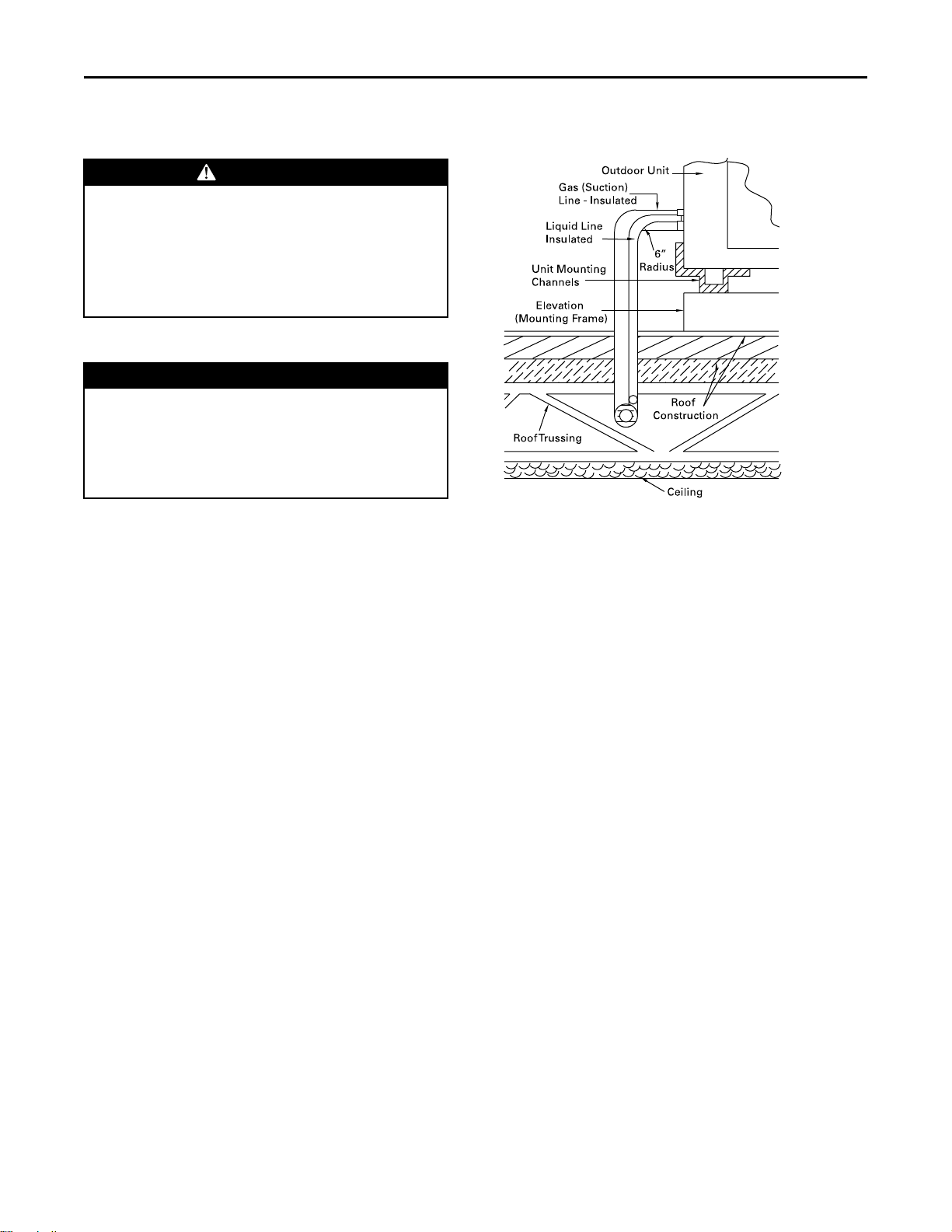
Rooftop Mounting
If the unit will be roof mounted, determine for certain
that the structure is strong enough to support the unit
and any required accessories, see “Weights,” p. 20. The
unit should be elevated on a level, field fabricated fourinch steel or wood 4" x 4" mounting frame. Complete
the frame and secure it into position before lifting the
unit to the roof. The mounting frame must support a
minimum of three of the unit’s four sides and should
span roof supports to distribute the load on the roof.
Figure 1. Roof mounted unit
Ground Level Mounting
For ground level installation, the unit base should be
adequately supported and hold the unit near level. The
installation must meet the guidelines set forth in local
codes. The support should extend two inches beyond
the unit base channels at all points. The unit and
support must be isolated from any adjacent structure to
prevent possible noise or vibration problems. Any
ground level location must comply with required
clearances given in the unit dimensional drawings (see
“Dimensional Data,” p. 10).
SS-SVX10E-EN
9
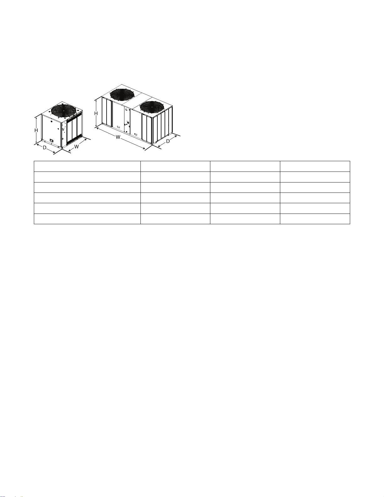
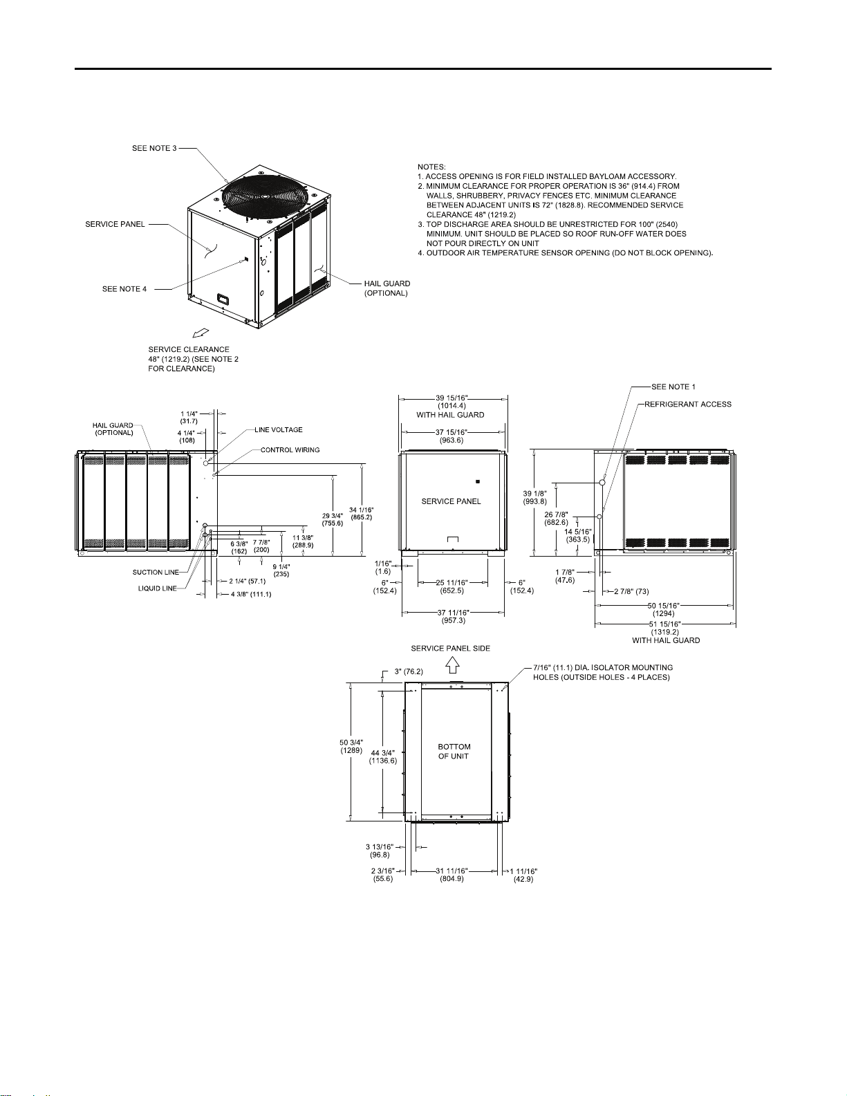
Dimensional Data
Figure 2. Height, width and depth measurements
H - in. (mm) W - in. (mm) D - in. (mm)
TTA061, 073, 076, 090 39.125 (993.8) 42.125 (1070) 36 (914.4)
TTA101, 120 39.125 (993.8) 52.125 (1324) 40 (1016)
TTA126, 150 45.125 (1146.1) 52.125 (1324) 40 (1016)
TTA156, 180, 201, 240 45.125 (1146.1) 95.5 (2425.7) 45.875 (1165.2)
TTA251, 300 51.125 (1298.6) 95.5 (2425.7) 45.875 (1165.2)
NNoottee:: Full dimensional data available on next pages.
10
SS-SVX10E-EN

Figure 3. 5, 6, 6.25 and 7.5 ton condensing unit, single compressor, microchannel
DDiimmeennssiioonnaall DDaattaa
SS-SVX10E-EN
11

DDiimmeennssiioonnaall DDaattaa
Figure 4. 5, 6, 6.25 and 7.5 ton condensing unit, dual compressor, microchannel
12
SS-SVX10E-EN
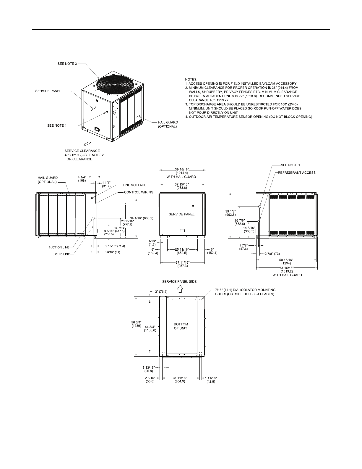
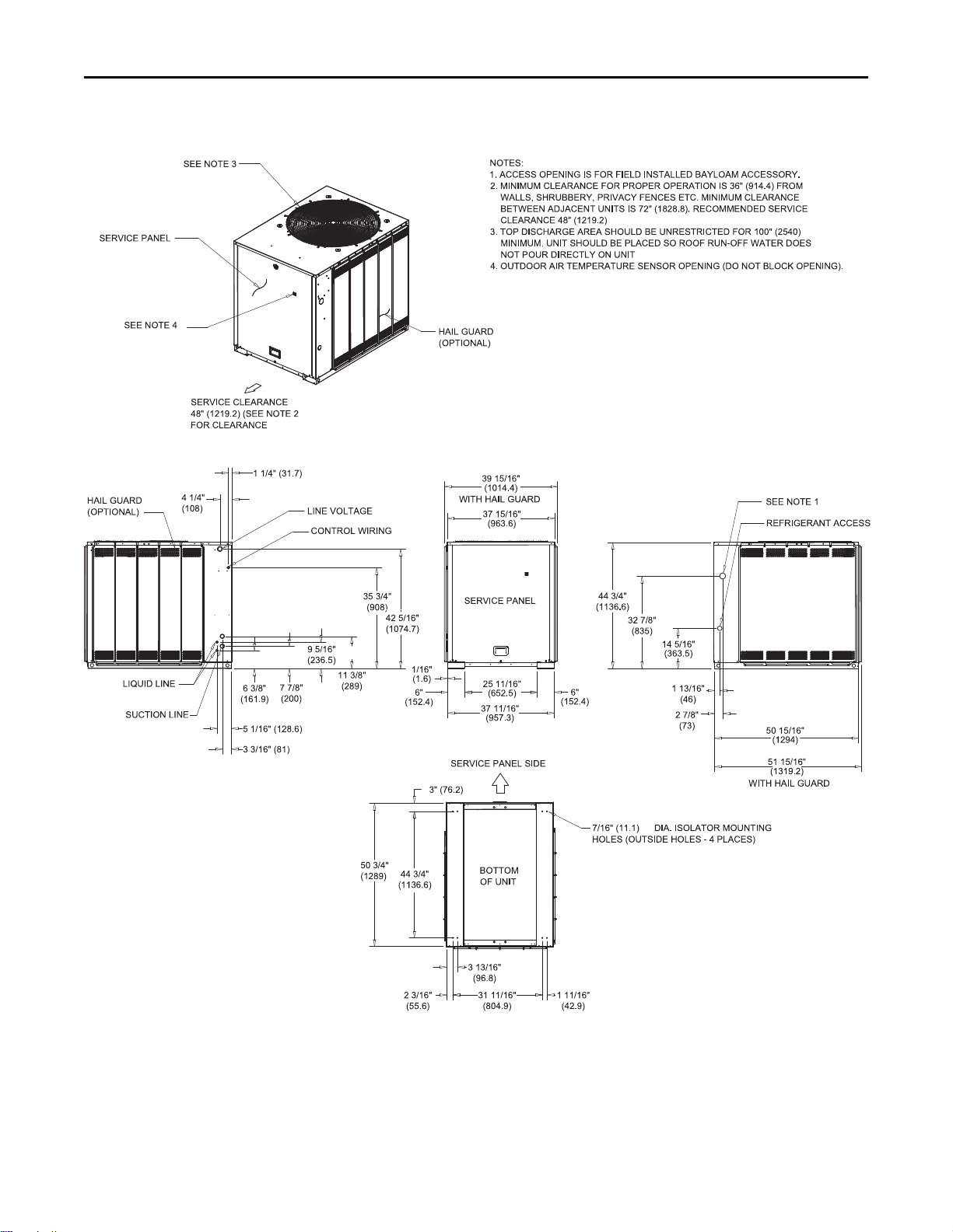
Figure 5. 8.33 and 10 ton condensing unit, single compressor. microchannel
DDiimmeennssiioonnaall DDaattaa
SS-SVX10E-EN
13
DDiimmeennssiioonnaall DDaattaa
Figure 6. 8.33 and 10 ton condensing unit, dual compressor, microchannel
14
SS-SVX10E-EN
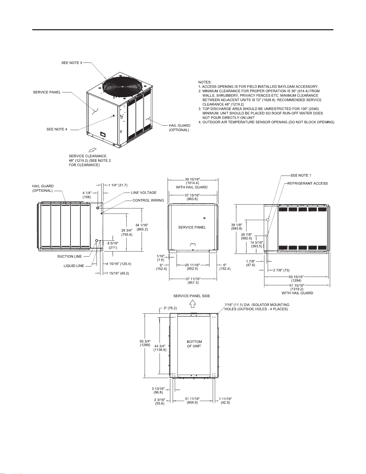
Figure 7. 8.33 and 10 condensing unit, manifolded compressor, tube and fin
DDiimmeennssiioonnaall DDaattaa
SS-SVX10E-EN
15
DDiimmeennssiioonnaall DDaattaa
Figure 8. 10.4 and 12.5 ton condensing unit, dual compressor, tube and fin
16
SS-SVX10E-EN
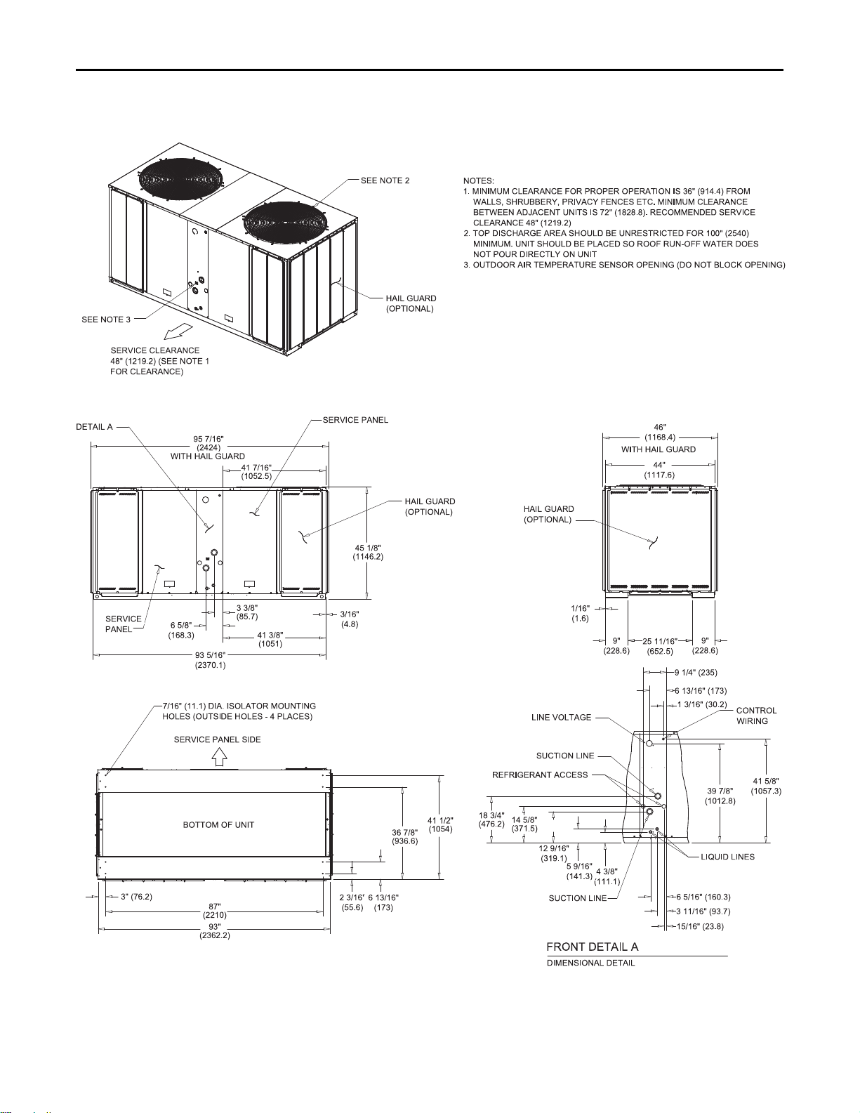
Figure 9. 13, 15, 16.7 and 20 ton condensing unit, dual compressor, tube and fin
DDiimmeennssiioonnaall DDaattaa
SS-SVX10E-EN
17
Loading...