


Thermostat
Model TZEMT400AB32MAA
User Guide
Contents |
|
Product Specifications............................................ |
2 |
Operation.................................................................. |
3 |
Thermostat Control Screen Function Control Buttons. 4 |
|
Minimized Display Mode.............................................. |
5 |
Menu Map.................................................................. |
6 |
User Settings............................................................ |
7 |
Set Clock..................................................................... |
7 |
Filter Service................................................................ |
8 |
Maint Service............................................................... |
9 |
Screen Timeout......................................................... |
10 |
F/C Settings............................................................... |
11 |
Sensor Calibration..................................................... |
12 |
Backlite/Display......................................................... |
13 |
Usage Graph........................................................... |
14 |
ESM Setpoints........................................................ |
15 |
ZWave Install.......................................................... |
16 |
Inclusion.................................................................... |
16 |
Exclusion................................................................... |
16 |
Inclusion and Exclusion............................................. |
16 |
Thermostat Info...................................................... |
17 |
Installer Settings.................................................... |
18 |
System Settings......................................................... |
19 |
Mechanical Settings.................................................. |
20 |
Fan Cycler Settings................................................... |
20 |
Schedules............................................................... |
21 |
Installation.............................................................. |
24 |
LED Reference........................................................ |
25 |
Warranty.................................................................. |
26 |
Index........................................................................ |
27 |

Product Specifications
Specification |
Description |
|
|
Product Model: |
TZEMT400AB32MAA |
|
|
Product: |
Thermostat for Heating and Cooling HVAC System control. |
|
Z-Wave™ RF communications enabled |
|
|
Thermostat |
|
|
|
Size: |
5.7” wide x 4.0” height x 1.2” depth |
|
|
Display: |
Graphical LCD, 2.75” x 1.5”, 64x128-pixel |
|
|
Backlight: |
Yes, Blue/white, Controllable, on, off, timeout |
|
|
Contrast: |
Adjustable on screen |
|
|
Buttons: |
6 |
|
|
LEDs: |
4 (3 green, 1 red) |
|
|
Power: |
24VAC from HVAC System |
|
|
HVAC System Type |
Standard (gas/electric) or Heat Pump |
Compatible: |
|
|
|
Multistage System Compatible: |
Standard HVAC Systems: 2 stage heating, 2-stage cooling |
|
Heat Pump Systems: 3 stage heating (2-compressor, 1 aux heat), 2-stage cooling |
|
|
Heat Pump change over valve: |
Selectable change over with cool or with heat |
|
|
Communications: |
Z-Wave™ RF |
|
|
Thermostat User Guide |
2 |

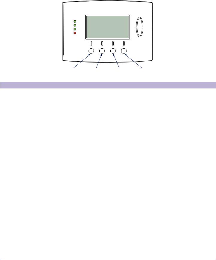
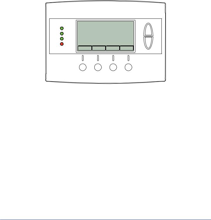
Operation
The model TZEMT400AB32MAA thermostat provides typical thermostat control of a central heating and cooling HVAC system. This thermostat also features a Z-Wave™ module for remote control.
|
|
|
|
|
|
Tempurature |
Clock Display |
11:15 |
AM |
|
|
|
Display |
|
|
|
|
|||
|
Sys Off |
72 |
77 H |
Setpoint |
||
LEDs |
|
|
||||
Status Indicator |
|
|
|
|
Up/Down Buttons |
|
Run |
|
|
|
74 C |
||
|
|
|
|
|
||
|
|
|
|
|
|
|
|
Filter |
AUTO |
AUTO |
|
|
|
|
|
|
|
|
||
|
MENU |
|
MODE |
FAN |
RUN |
|
Dynamic Labels |
|
|
|
|
|
Setpoint Display |
|
|
|
|
|
|
|
Function Control Buttons
Normally, the thermostat displays the thermostat control screen as shown above.
Item |
Description |
Notes |
|
|
|
Clock Display |
The current time is displayed in the upper |
See Set Clock on page 7 for more |
|
left corner of the main screen. The time will |
information. |
|
blink when the clock has not been set. |
|
|
|
|
Status Indicator LEDs |
The thermostat has four LEDs that display |
See LED Reference on page 25 for more |
|
status information. The LEDs have dynamic |
information. |
|
labels. |
|
|
|
|
Dynamic Labels and |
The buttons are defined by the dynamic |
|
Function Control Buttons |
labels above each button. As you navigate |
|
|
through menus, the labels for the buttons |
|
|
will change. |
|
|
|
|
Setpoint Display and |
The current heat and cool setpoints are |
The setpoints will push each other if they |
Setpoint Up/Down |
displayed. These setpoints may be set |
are adjusted to within the minimum heat/ |
Buttons |
using the Z-Wave control system, the |
cool separation setting. This is normally 3 |
|
thermostat’s internal schedule, or by |
degrees. |
|
pressing the Setpoint Up/Down buttons. In |
The internal schedule is disabled by |
|
HEAT mode, the Setpoint Up/Down buttons |
|
|
default. See Schedules on page 21 for more |
|
|
change the heat setpoint. In COOL mode, |
information. |
|
they change the cooling setpoint. In AUTO |
|
|
|
|
|
mode, the buttons change the last call’s |
|
|
heating or cooling setpoint. |
|
|
|
|
Temperature Display |
The thermostat displays the current |
The internal temperature sensor can |
|
temperature as sensed by the internal |
be adjusted as necessary. See Sensor |
|
temperature sensor. |
Calibration on page 12 for more information. |
|
|
|
Thermostat User Guide |
3 |
Operation |
Thermostat Control Screen Function Control Buttons |
|
|
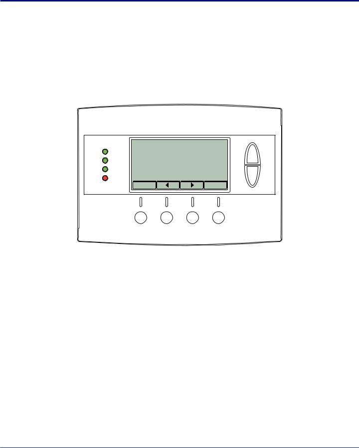
Thermostat Control Screen Function Control Buttons
11:15 |
AM |
|
|
|
|
|
|
|
|
Sys Off |
72 |
77 |
H |
||||||
|
|
||||||||
Run |
|
|
|
74 |
C |
|
|
|
|
|
|
|
|
|
|
|
|||
|
|
|
|
|
|
||||
|
|
|
|
|
|
|
|||
|
|
|
|
|
|
|
|||
|
|
|
|
|
|
|
|
|
|
Filter |
AUTO |
AUTO |
|
|
|
|
|
|
|
|
|
|
|
|
|
|
|
||
MENU |
|
MODE |
FAN |
RUN |
|||||
|
|
|
|
|
|
|
|
|
|
Menu Button |
System |
Fan Mode |
Schedule |
|
Mode Button |
Button |
Mode Button |
Button |
Description |
|
|
Menu |
Other thermostat menus can be accessed by pressing the MENU button. |
|
|
System Mode |
Used to change the system mode: |
|
Off: System off |
|
Heating: Heating only on |
|
Cooling: Cooling only on |
|
Auto: Heating/Cooling on as necessary |
|
|
Fan Mode |
Used to change the fan mode: |
|
Auto: Fan on when cooling/heating is necessary |
|
On: Fan constantly on |
|
|
Schedule Mode |
Used to change the schedule mode: |
|
Hold: System maintains the current temperature setpoints. Schedules are disregarded. |
|
Run: Run the system schedule (or Z-Wave controlled schedule) |
|
Energy Saving Mode: Temperature setpoints in ESM Setpoints are maintained. See ESM |
|
Setpoints on page 15 for more information. |
|
|
Thermostat User Guide |
4 |
Operation |
Minimized Display Mode |
|
|
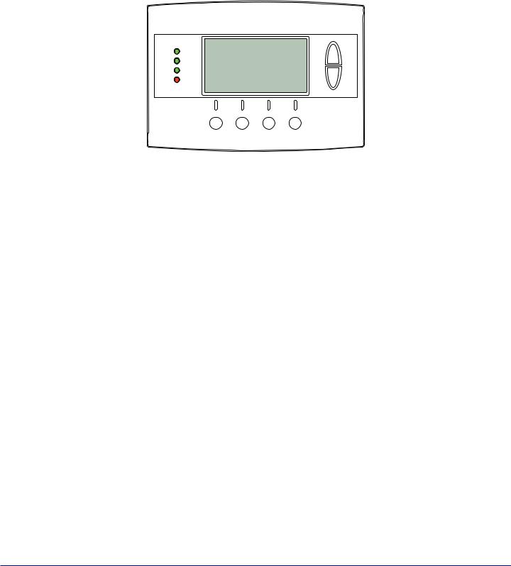
Minimized Display Mode
Optionally, you can set the thermostat to show only the temperature in minimized display mode. This mode can be enabled or disabled in the Users Settings screen.
ÎÎ See Screen Timeout on page 10 for more information.
72
Thermostat User Guide |
5 |

Menu Map
The menus are accessed by pressing the MENU button on the main screen.
“User Settings”
Set Clock
Filter Service
Maint Service
Screen Timeout
F/C Settings
Sensor Calibration
Backlite/Display
“Usage Graph”
“ESM Setpoints”
“ZWave Install”
“Thermostat Info”
“Installer Settings” (hidden)
Display Lock
System Settings
Mechanical SettingsType
Fan Type
C/O Type
2nd Stage HeatAux Heat
2nd Stage CoolSched Enable
Recovery EnableH/C Delta
H Delta Stg1 ON
H Delta Stg1 OFF
H Delta Stg2 ON
H Delta Stg2 OFF
H Delta Stg3 ON
H Delta Stg3 OFF
C Delta Stg1 ON
C Delta Stg1 OFF
C Delta Stg2 ON
C Delta Stg2 OFF
Max Heat SP
Min Cool SP
Min Run Time
Min Off Time
Fan Cycler
Fan ON Time
Fan OFF Time
Restore Defaults
“Schedules” (disabled by default)
Heat and Cool
Preset:Comfort
Preset:EnergyStar
Copy (small c on each schedule screen)
Thermostat User Guide |
6 |
User Settings
Set Clock
The Set Clock screen allows you to set the thermostat’s internal clock.
ÎÎ If the clock has been reset by an extended power outage, the clock display on the thermostat screen will blink. Press the MENU button to go directly to the Set Clock screen.
Set Clock
Time 11 : 15 AM
Date 01 / 01 / 09
Day Thu
+
-
Back |
Set |
Set the Clock
1.Press the MENU button.
2.Scroll to User Settings and press the Select button.
3.Scroll to Set Clock and press the Select button.
4.Scroll to the item you want to change (hour, minute, day part, month, day, year, day of week).
5.Press the plus (+) or minus (-) buttons to adjust the item.
6.Press the Set button to save the changes.
Thermostat User Guide |
7 |
User Settings |
Filter Service |
|
|
Filter Service
The Filter Service screen will show the accumulated Filter Runtime hours as well as the Service Interval that will be used to trigger a Filter Message. Any type of HVAC operation that causes the HVAC system fan to run will cause the Filter Runtime value to increase.
When the Runtime hours equals the Service Interval hours, the Red LED will flash along with a “Filter” message to remind you to replace the filter. Once the filter has been replaced, press the Reset button to reset the Filter Runtime value to zero.
|
Filter Service |
|
|
|
Filter Runtime |
|
184 |
HRS |
|
Service Interval |
|
300 |
HRS |
|
Done |
+ |
- |
|
Reset |
View/Reset Filter Runtime
1.Press the MENU button.
2.Scroll to User Settings and press the Select button.
3.Scroll to Filter Service and press the Select button. The Filter Runtime is displayed in hours.
4.To reset the Filter Runtime counter, press the Reset button.
ÎÎ The Filter Runtime counter should be reset each time the filter is changed.
Change the Filter Service Interval
1.Press the MENU button.
2.Scroll to User Settings and press the Select button.
3.Scroll to Filter Service and press the Select button.
4.Press the plus (+) or minus (-) buttons to adjust the service interval.
ÎÎ The service interval can be set between 100 and 4000 hours in 100 hour increments.
Disable the Filter Service Interval
When the filter service interval is disabled, the runtime counter will continue to count the runtime, but the filter service indicator will never be displayed.
1.Press the MENU button.
2.Scroll to User Settings and press the Select button.
3.Scroll to Filter Service and press the Select button.
4.Press the minus (-) button until Disabled is displayed
Thermostat User Guide |
8 |
User Settings |
Maint Service |
|
|
Maint Service
The Maintenance Service screen shows the accumulated Heat and Cool Runtime hours as well as the Service Interval that will be used to trigger a Maintenance Message. Any HEAT or COOL type of HVAC operation will cause the respective Runtime values to increase.
When the combined HEAT and COOL Runtime hours equals the Service Interval hours, the Red LED will flash along with a “Maint” message to remind you your HVAC system may require periodic maintenance. Press the Menu button to enter the Filter Service screen. The Reset button can be pressed and the HEAT and COOL Runtime values will be reset to zero.
|
Maintenance Service |
|
|
Heat Runtime |
200 |
HRS |
|
Cool Runtime |
300 |
HRS |
|
Service Interval |
3000 HRS |
||
Done |
+ |
- |
Reset |
Change the Maintenance Service Interval
1.Press the MENU button.
2.Scroll to User Settings and press the Select button.
3.Scroll to Maint Service and press the Select button.
4.Press the plus (+) or minus (-) buttons to adjust the service interval.
ÎÎ The service interval can be set between 200 and 4000 hours in 100 hour increments.
Disable the Maintenance Service Interval
When the maintenance service interval is disabled, the runtime counter will continue to count the runtime, but the maintenance service indicator will never be displayed.
1.Press the MENU button.
2.Scroll to User Settings and press the Select button.
3.Scroll to Maint Service and press the Select button.
4.Press the minus (-) button until Disabled is displayed
Thermostat User Guide |
9 |
 Loading...