


 Loading...
Installation
Operation
Programming
VAV VV550 LonTalk
Controller
|
|
May 2010 |
VAV-SVP01A-EN |
Warnings, Cautions and Notices
Warnings, Cautions and Notices. Note that warnings, cautions and notices appear at appropriate intervals throughout this manual. Warnings are provided to alert installing contractors to potential hazards that could result in personal injury or death. Cautions are designed to alert personnel to hazardous situations that could result in personal injury, while notices indicate a situation that could result in equipment or property-damage-only accidents.
Your personal safety and the proper operation of this machine depend upon the strict observance of these precautions.
ATTENTION: Warnings, Cautions and Notices appear at appropriate sections throughout this literature. Read these carefully.
WARNING: Indicates a potentially hazardous situation which, if not avoided, could result in death or serious injury.
CAUTION: Indicates a potentially hazardous situation which, if not avoided, could result in minor or moderate injury. It could also be used to alert against unsafe practices.
NOTICE: Indicates a situation that could result in equipment or property-damage-only accidents.
WARNING
This equipment is to be serviced/installed by qualified personnel ONLY. Under NO circumstances should an unqualified person service/install it. Servicing/installing this equipment is a job requiring specific knowledge and MUST be left to a professional. It involves working with hazardous components that are potentially life threatening if not handled properly. Improperly installed, adjusted or altered equipment by an unqualified person could result in death or serious injury.
WARNING
Personal Protective Equipment (PPE) Required!
Installing/servicing this unit could result in exposure to electrical, mechanical and chemical hazards.
•Before installing/servicing this unit, technicians MUST put on all Personal Protective Equipment (PPE) recommended for the work being undertaken. ALWAYS refer to appropriate MSDS sheets and OSHA guidelines for proper PPE.
•When working with or around hazardous chemicals, ALWAYS refer to the appropriate MSDS sheets and OSHA guidelines for information on allowable personal exposure levels, proper respiratory protection and handling recommendations.
•If there is a risk of arc or flash, technicians MUST put on all necessary Personal Protective Equipment (PPE) in accordance with NFPA70E for arc/flash protection PRIOR to servicing the unit.
Failure to follow recommendations could result in death or serious injury.
© 2010 Trane All rights reserved |
VAV-SVP01A-EN |

Warnings, Cautions and Notices
WARNING
Electrocution and Fire Hazards with Improperly Installed and Grounded Field Wiring!
Improperly installed and grounded field wiring poses FIRE & ELECTROCUTION hazards. To avoid these hazards, you MUST follow requirements for field wiring installation and grounding as described in NEC and your local/state electrical codes. All field wiring MUST be performed by qualified personnel. Failure to follow these requirements could result in death or serious injury.
Overview of Manual
Note: One copy of this document ships inside the control panel of each unit and is customer property. It must be retained by the unit's maintenance personnel.
This booklet describes proper installation, operation, and maintenance procedures for delivered air systems. By carefully reviewing the information within this manual and following the instructions, the risk of improper operation and/or component damage will be minimized. It is important that periodic maintenance be performed to help assure trouble free operation. A maintenance schedule is provided at the end of this manual. Should equipment failure occur, contact a qualified service organization with qualified, experienced HVAC technicians to properly diagnose and repair this equipment.
VAV-SVP01A-EN |
3 |

Table of Contents
General Information . . . . . . . . . . . . . . . . . . . . . . . . . . . . . . . . . . . . . . . . . . . . . . . . . . . . 6
Chapter Overview . . . . . . . . . . . . . . . . . . . . . . . . . . . . . . . . . . . . . . . . . . . . . . . . . . 6
Unit Control Module VAV VV550 Controller . . . . . . . . . . . . . . . . . . . . . . . . . . . 6
Specifications . . . . . . . . . . . . . . . . . . . . . . . . . . . . . . . . . . . . . . . . . . . . . . . . . . . . . 7
VV550 Enhancements . . . . . . . . . . . . . . . . . . . . . . . . . . . . . . . . . . . . . . . . . . . . . . 8
VV550 Features . . . . . . . . . . . . . . . . . . . . . . . . . . . . . . . . . . . . . . . . . . . . . . . . . . . . 9
Shipping & Storage . . . . . . . . . . . . . . . . . . . . . . . . . . . . . . . . . . . . . . . . . . . . . . . 11
Data Lists . . . . . . . . . . . . . . . . . . . . . . . . . . . . . . . . . . . . . . . . . . . . . . . . . . . . . . . . 12
VAV Start Up/Check Out Procedure . . . . . . . . . . . . . . . . . . . . . . . . . . . . . . . . . . . . . . |
14 |
Chapter Overview . . . . . . . . . . . . . . . . . . . . . . . . . . . . . . . . . . . . . . . . . . . . . . . . . |
14 |
VV550 Pre-Power Check-Out . . . . . . . . . . . . . . . . . . . . . . . . . . . . . . . . . . . . . . . . |
14 |
VV550 Power Wiring . . . . . . . . . . . . . . . . . . . . . . . . . . . . . . . . . . . . . . . . . . . . . . |
15 |
Light Emitting Diode (LED) Operations . . . . . . . . . . . . . . . . . . . . . . . . . . . . . . . |
16 |
Communication Wiring . . . . . . . . . . . . . . . . . . . . . . . . . . . . . . . . . . . . . . . . . . . . |
19 |
Wireless Zone Sensor . . . . . . . . . . . . . . . . . . . . . . . . . . . . . . . . . . . . . . . . . . . . . |
27 |
VAV VV550 Controller Programming and Operation . . . . . . . . . . . . . . . . . . . . . . |
42 |
Chapter Overview . . . . . . . . . . . . . . . . . . . . . . . . . . . . . . . . . . . . . . . . . . . . . . . . . |
42 |
Accessing Rover/Comm5 LonTalk . . . . . . . . . . . . . . . . . . . . . . . . . . . . . . . . . . . |
42 |
VV550 Controller Device Home Tabs: At a Glance . . . . . . . . . . . . . . . . . . . . . |
44 |
Entering and Exiting the Service Mode . . . . . . . . . . . . . . . . . . . . . . . . . . . . . . |
51 |
Overriding VAVs . . . . . . . . . . . . . . . . . . . . . . . . . . . . . . . . . . . . . . . . . . . . . . . . . . |
51 |
VAV VV550 Controller Device Home Tabs: Instructions . . . . . . . . . . . . . . . . . . . . |
54 |
Chapter Overview . . . . . . . . . . . . . . . . . . . . . . . . . . . . . . . . . . . . . . . . . . . . . . . . . |
54 |
Configuration . . . . . . . . . . . . . . . . . . . . . . . . . . . . . . . . . . . . . . . . . . . . . . . . . . . . |
54 |
Setpoints Tab . . . . . . . . . . . . . . . . . . . . . . . . . . . . . . . . . . . . . . . . . . . . . . . . . . . . |
54 |
Unit Tab . . . . . . . . . . . . . . . . . . . . . . . . . . . . . . . . . . . . . . . . . . . . . . . . . . . . . . . . . |
57 |
Setup Tab . . . . . . . . . . . . . . . . . . . . . . . . . . . . . . . . . . . . . . . . . . . . . . . . . . . . . . . . |
59 |
Inputs Tab . . . . . . . . . . . . . . . . . . . . . . . . . . . . . . . . . . . . . . . . . . . . . . . . . . . . . . . |
61 |
Outputs Tab . . . . . . . . . . . . . . . . . . . . . . . . . . . . . . . . . . . . . . . . . . . . . . . . . . . . . . |
63 |
Test Tab . . . . . . . . . . . . . . . . . . . . . . . . . . . . . . . . . . . . . . . . . . . . . . . . . . . . . . . . . |
64 |
Other Tab . . . . . . . . . . . . . . . . . . . . . . . . . . . . . . . . . . . . . . . . . . . . . . . . . . . . . . . . |
65 |
Overrides . . . . . . . . . . . . . . . . . . . . . . . . . . . . . . . . . . . . . . . . . . . . . . . . . . . . . . . . |
66 |
Sequence of Operations . . . . . . . . . . . . . . . . . . . . . . . . . . . . . . . . . . . . . . . . . . . . . . . . |
67 |
Chapter Overview . . . . . . . . . . . . . . . . . . . . . . . . . . . . . . . . . . . . . . . . . . . . . . . . . |
67 |
Calibration . . . . . . . . . . . . . . . . . . . . . . . . . . . . . . . . . . . . . . . . . . . . . . . . . . . . . . . |
67 |
4 |
VAV-SVP01A-EN |

Occupancy Modes . . . . . . . . . . . . . . . . . . . . . . . . . . . . . . . . . . . . . . . . . . . . . . . . |
68 |
Space Temperature Control: Single Duct Units . . . . . . . . . . . . . . . . . . . . . . . . |
69 |
Space Temperature Control: Fan-Powered Units . . . . . . . . . . . . . . . . . . . . . . |
72 |
Ventilation Flow Control . . . . . . . . . . . . . . . . . . . . . . . . . . . . . . . . . . . . . . . . . . . |
74 |
Flow Tracking . . . . . . . . . . . . . . . . . . . . . . . . . . . . . . . . . . . . . . . . . . . . . . . . . . . . |
76 |
Air and Water Balancing . . . . . . . . . . . . . . . . . . . . . . . . . . . . . . . . . . . . . . . . . . . . . . . |
78 |
Chapter Overview . . . . . . . . . . . . . . . . . . . . . . . . . . . . . . . . . . . . . . . . . . . . . . . . . |
78 |
Air Balancing . . . . . . . . . . . . . . . . . . . . . . . . . . . . . . . . . . . . . . . . . . . . . . . . . . . . . |
78 |
Rover Air and Water Balancing Tool . . . . . . . . . . . . . . . . . . . . . . . . . . . . . . . . . |
79 |
Troubleshooting . . . . . . . . . . . . . . . . . . . . . . . . . . . . . . . . . . . . . . . . . . . . . . . . . . . . . . . 83
Chapter Overview . . . . . . . . . . . . . . . . . . . . . . . . . . . . . . . . . . . . . . . . . . . . . . . . . 83
Diagnosing the Problem . . . . . . . . . . . . . . . . . . . . . . . . . . . . . . . . . . . . . . . . . . . 83
Troubleshooting Procedures . . . . . . . . . . . . . . . . . . . . . . . . . . . . . . . . . . . . . . . 87
Trane/Honeywell Proportional Valve Check Out Procedures . . . . . . . . . . . 105
VAV-SVP01A-EN |
5 |

General Information
Chapter Overview
This chapter contains information about the following:
•Unit Control Module VAV VV550 Controller
•Specifications
•VAV VV550 Controller Enhancements
•VAV VV550 Controller Features
•Shipping & Storage
•Data Lists
Unit Control Module VAV VV550 Controller
The VV550 is a microprocessor-based, Direct Digital Controller (DDC) for the (Variable Air Volume) VAV terminal unit. Units have been made with either pneumatic, analog electronic, or microprocessor controls (DDC VAV). This manual discusses only terminal units with Comm 5 VAV VV550 DDC Controller. Factory installed DDC/VAV controls are available with all single duct terminal units, dual duct units, as well as parallel fan-powered and series fan-powered units. Two VAV VV550 Controllers are required for dual duct units (one for the heating duct and one for the cooling duct) and another application requiring to controllers is Flow tracking (one unit controller is programmed from the factory with the Space temperature program and the other is downloaded with the Flow tracking program.
The VAV VV550 Controller can be configured from the factory with three different application programs. The VAV VV550 Controller programmed for space temperature control modulates a VAV's damper blade based on a zone temperature, measured airflow, and set points to continuously control conditioned air delivery to the space. The volume of incoming air is monitored and the damper adjusts to provide accurate control independent of the duct pressure. The damper modulates between operator set points depending on space conditions. Additionally, fan and heat outputs may be energized depending on the application.
The VAV VV550 Controller programmed for ventilation flow control is applied to a VAV terminal and used to temper cold outdoor air (OA) that is brought into a building for ventilation purposes. The tempered air is intended to supply an air-handling unit (AHU), which provides comfort control to the zones it is serving. The VAV terminal supplies the correct amount of ventilation air and, when reheat is added, tempers the ventilation air to reduce the load on the air handler by sensing the discharge air temperature of VAV unit.
The VAV VV550 Controller programmed for Flow Tracking Control (FTC) has two VAV VV550 Controllers working together to provide flow tracking control. One VAV VV550 controller is programmed from the factory with the Space temperature program and the other is downloaded with the Flow tracking program. The space temperature controller airflow output is bound to the flow tracking controller airflow setpoint input. The flow tracking controller adds the configured airflow tracking offset (positive or negative) to the airflow setpoint (communicated airflow setpoint) and controls the airflow to this setpoint.
The VAV VV550 Controller utilizes an FTT-10A Free Topology transceiver, which supports nonpolarity sensitive, free topology wiring, which allows the system installer to utilize star, bus, and loop architectures. Available inputs include a twisted/shielded communication link, zone sensor, auxiliary temperature sensor (optional), and Occupy/Unoccupied Sensor (optional), and 24VAC power.
6 |
VAV-SVP01A-EN |

General Information
Specifications
Power Requirements
The UCM VV550 requires 18-32 Vac (24VAC nominal), 50/60 Hz, and up to 50 VA, depending on the number of heat outputs (stages), which consume 10 VA each.
Operating Environments - VAV VV550 Controller
32° to 140°F (0° to 60°C), 5% to 90% relative humidity, non-condensing
Storage Environments - VAV VV550 Controller
-40° to 185°F (-40° to 85°C), 5% to 90% relative humidity, non-condensing From 5 to 95% non-condensing
Relative humidity:
From 5 to 95% non-condensing
Analog Inputs
Space temperature; thermistor: 10 kΩ@ 77°F (25°C) From 14 to 122°F (-10 to 50°C) Space setpoint; potentiometer: 1 kΩ From 50 to 90°F (-10 to 32.2°C)
Primary/discharge air temperature; thermistor: 10 kΩ@ 77°F (25°C) From -40 to 212°F (-40 to 100°C) Primary air flow; pressure transducer: From 0 to 2 in. water (0 to 498 Pa)
Binary Input
Occupancy or generic (dry contact)
Binary Outputs
Air valve close: maximum output rating: 12 VA
Air valve open: maximum output rating: 12 VA
Heat stage 1: maximum output rating: 12 VA
Heat stage 2: maximum output rating: 12 VA
Heat stage 3/Fan on/off: maximum output rating: 12 VA
Agency Listings/Compliance
VAV VV550 Controller:
UL 873 and CSA C22.2 No. 24-93:
Temperature Indicating and Regulating
Equipment
VAV VV551 Controller:
UL-916-PAZX-energy management
CUL-C22.2-signal devices-Canada
UL 94-5V (UL flammability rating for plenum use)
FCC Part 15, Class A
CE marked
Mounting
Typically, the VAV VV550 Controller is factory installed. However, the VAV VV550 Controller is available with retrofit kits, in which case it must be field installed, and it’s named VV551.
Tracer Summit and VV550 Communications Link Wiring
Use 22 AWG Level 4 unshielded communication wire for most Comm5 installations. Limit Comm5 links to 4,500 ft and 60 devices maximum (without a repeater). Use one repeater for an additional 4,500 ft, 60 devices, and 8 communication stubs. Refer to Chapters 2 and 3 for further information about wire selection.
VAV-SVP01A-EN |
7 |

General Information
VV550 Enhancements
Controller Interface Flexibility
VV550 controller allows VAV units to communicate on a Trane Comm5 or LonTalk. This controller works in standalone mode, peer-to-peer with one or more other units, or when connected to a Trane Tracer Summit or a 3rd party building automation system that supports LonTalk.
Manual Test Function
The VV550 controller includes a manual test button that allows the field technician to manually exercise the outputs of the controller. This feature is simple enough for the electrician to use to check valve operation. Though this feature is standard on other Comm5 controllers, the feature is not available on the VAV VV550 Controller.
Flow Tracking
The VV550 controller has been designed with the ability to be applied in flow tracking applications. This allows the controller to pair with one of its peers to mirror the flow if that lead box, with or without an offset (positive or negative static pressure as desired).
Ventilation Flow Control w/ Tempering
The VV550 controller has been designed with the ability to be applied in ventilation flow control applications. These applications pair a fresh air unit with ventilation boxes to provide fresh (tempered) air to a floor/area. This feature also includes a freeze protection sequence to protect the hot water reheat coil from low supply air temperatures.
Auto-commissioning Sequence
The VV550 controller has been designed with an auto-commissioning sequence. With a discharge air temperature sensor, this feature exercises the air valve, fan, and heat in the box and records the temperature before and after the action. This allows the installer to more easily checkout the operation of the box and commission by exception.
Automatic Calibration
The VV550 controller has been designed to automatically calibrate the flow transducer each time the box transitions to unoccupied. This eliminates the need to initiate/schedule calibration for most installations. The exception is 24/7 sites, in which case Tracer Summit can be used to initiate/ schedule calibration.
Temporary Heat (Construction Mode)
Upon reset (and power-up) if the controller does not detect a valid space temperature the controller will provide temporary heat by driving the air valve to the heating maximum position. Of course, the box will only provide heat if hot air is being provided by the air-handling unit.
Local versus Remote Reheat Flexibility
The controller can be configured to have local and/or remote heat. Plus, configuration flexibility is offered that allows the installer to select whether local or remote heat has priority.
Zone Sensor Air Balancing
When applied with a Trane zone sensor module that includes a setpoint thumbwheel and ON and CANCEL buttons, the controller offers a zone sensor air-balancing feature. This feature allows the balancing contractor to drive the box to either its minimum or maximum flow setting by turning the setpoint thumbwheel on the zone sensor module. Then, the balancing contractor can calibrate the flow reading by pressing the ON (adjusts the reading upwards) or CANCEL (adjusts the reading downwards) buttons on the zone sensor module.
8 |
VAV-SVP01A-EN |

General Information
Flash Download
The VAV controller has been designed with flash memory. This allows us the option of upgrading the controller in the field (features, corrections to defects) without changing out the controller.
Air/Water Balancing Application
An air/water balancing application is available in Rover that simplifies the startup, checkout and balancing of VAV systems. This application is specifically designed for the balancing contractor.
Service Pin from the Trane Zone Sensor
Several Comm5 installation and commissioning scenarios have the technician pressing the "service" button on the controller. By doing so, a service pin message is broadcast and received by either the Rover service tool or by Tracer Summit (depending on the scenario). Because access to the service button on the controller is often difficult, functionality has been included in the controller that allows the technician to press and hold the ON button on the zone sensor to replicate a service button press.
Trane Controller Compatibility
The VV550 is a Comm5 controller. As such, the controller is compatible with the latest generation of Trane controls. This allows the VV550 controller to exist on the same communication wire as the rest of our Comm5 controllers and share data with them as required. Additional inputs and outputs can easily be added to the same communication link (Tracer MP503) for any required auxiliary functions. In the past the cost of adding additional inputs and outputs (Comm4 link by way of a UPCM) was much less cost-effective.
Drive Min and Max from Zone Sensor
When applied with a Trane zone sensor module that includes a thumbwheel setpoint, the VV550 controller can easily be overridden to minimum and maximum flow. By simply turning the thumbwheel to "*" (end of range in one direction) the controller drives the air valve to the minimum cooling flow setpoint. Similarly, turning the thumbwheel to the and "**" (end of range in the other direction) the controller drives the air valve to the maximum cooling flow setpoint.
VV550 Features
Auto-commissioning Report (Tracer Summit)
Tracer Summit v15 and greater includes an auto-commissioning report that extracts and formats the commissioning data for each VAV controller. This commissioning report is valuable both for the installer and for the owner. The feature enables the system to be commissioned by exception -- a benefit for the installer. The feature also can be used as validation -- valuable to the owner.
Simpler VAS
Tracer Summit v15 includes a new VAV Air System (VAS) specifically designed for Comm5 controllers. This new VAS was designed to be much simpler to understand and setup compared to the existing (Comm3/4) VAS.
Static Pressure Optimization
As a part of the standard application, VAS calculates the duct static pressure setpoint based on the most open VAV box. Until Tracer Summit v15, this feature was provided by way of field custom programming.
Ventilation Optimization
As a part of the standard application, the VAV system has the ability to calculate the ventilation setpoint for the air-handling unit. In addition, the VV550 controller has a ventilation ratio limit feature that automatically increases airflow to maintain the required ventilation while operating
VAV-SVP01A-EN |
9 |

General Information
within system limits for outside air percent concentrations in the supply air stream. Until Tracer Summit v15, this feature was provided by way of field custom programming.
CO2 Based Demand Control Ventilation
As a part of the standard application, the VAV system has the ability to calculate the ventilation setpoint for the air-handling unit based on the CO2 in one or more spaces. Until Tracer Summit v15, this feature was provided by way of field custom programming. Plus, functionality was added to the VV550 controller to support this feature (as standard). Providing the equivalent functionality with the current VAV controller would require lots of custom programming.
Ventilation Flexibility
Ventilation can be managed in the following ways:
•Fixed occupancy ventilation setpoint
•Scheduled (or otherwise calculated) ventilation setpoint
•Occupancy sensor to switch between normal and reduced ventilation
•CO2 sensor for demand-controlled ventilation
Note: CO2 sensor input not available on VV550.
Temperature Statistics
As a part of the standard application, VAS calculates the minimum space temperature (and source), maximum space temperature (and source), and the average space temperature. Until Tracer Summit v15, this feature was provided by way of field custom programming.
VAV VV550 Controller Compatibility
The VAV VV550 Controller is designed with LonWorks technology and will be LonMark certified. VV550 controller allows VAV units to communicate on a Trane Comm5 or LonTalk link. This controller works in standalone mode, peer-to-peer with one or more other units, or when connected to a Trane Tracer Summit or a 3rd party building automation system that supports LonTalk. The Space Comfort Controller (SCC) is the profile assigned to the VV550 controller.
VAV VV550 Controller Outputs
VAV VV550 Controller Triac outputs for controlling a fan or reheat are rated at 12 VA each.
Wiring Diagram
Figure 2, p. 17 shows a typical wiring diagram for the redesigned VAV VV550 hardware. The new service part number is BRD2960.
10 |
VAV-SVP01A-EN |
General Information
Figure 1. VV550 board layout
VAV VV550 controller and VAV 4.2 controller comparisons
VAV VV550 |
VAV 4.2 |
|
|
|
|
Supports Comm5 |
Supports only Comm4 or Comm3 (VariTrac or VariTrane) |
|
|
|
|
No local CO2 sensor input. Uses only a communicated value |
Local CO2 sensor input is available. |
|
|
|
|
Single star (*) initiates cool minimum airflow override. |
Single star (*) initiates maximum flow override after pressing the ON |
|
button. Override is held until you move the thumbwheel. |
||
|
||
|
|
|
Double star (**) initiates cool maximum airflow override. |
Double star (**) initiates unoccupied override after pressing the ON |
|
button. Override is held until you move the thumbwheel. |
||
|
||
|
|
|
Does not support VariTrac central control panel (CCP2 and CCP3). |
Does not support VariTrac CCP2 and CCP3. |
|
|
|
|
Supports ventilation flow control |
Does not support ventilation flow control. |
|
|
|
|
Supports flow tracking control. |
Does not support flow tracking control. |
|
|
|
|
Supports enhanced ventilation control sequences. |
Does not support enhanced ventilation control sequence. |
|
|
|
|
Supports auto-commissioning sequence. |
Does not support auto-commissioning sequence. |
|
|
|
|
Supports zone sensor air balance sequences. |
Does not support zone sensor air balance sequence. |
|
|
|
Shipping & Storage
Each VAV product and its service literature are shipped in the same package. When unpacking, make sure that the literature is not lost or discarded with the packing material. Visually inspect the individual components for obvious defects or damage. All components are thoroughly inspected before leaving the factory. Any claims for damage incurred during shipment must be filed with the carrier.
When any component of the VAV system and/or field installed accessories must be stored for a period of time prior to being installed, they must be protected from the elements. The storage location temperature should be between -40° to 150°F (-40° to 65.6°C) and the relative humidity should be 10% to 90%, non-condensing. The warranty will not cover damage to the VAV system or controls due to negligence during storage. A controlled indoor environment must be used for storage.
VAV-SVP01A-EN |
11 |

General Information
Data Lists
If you’re going to connect to a generic building automation system, use Table 1, p. 12 and Table 2, p. 13 for your points list.
Table 1. Input/output listing
Input Description |
Input |
SNVT type |
Output description |
Output |
SNVT type |
|
|
|
|
|
|
|
|
Space temperature |
nviSpaceTemp |
SNVT_temp_p |
Space temperature |
nvoSpaceTemp |
SNVT_temp_p |
|
|
|
|
|
|
|
|
Setpoint |
nviSetpoint |
SNVT_temp_p |
Unit status, mode |
nvoUnitStatus |
SNVT_hvac_status |
|
|
|
|
|
|
|
|
Occupancy, schedule |
nviOccSchedule |
SNVT_tod_event |
Effective setpoint |
nvoEffectSetpt |
SNVT_temp_p |
|
|
|
|
|
|
|
|
Occupancy, manual |
nviOccManCmd |
SNVT_occupancy |
Effective occupancy |
nvoEffectOccup |
SNVT_occupancy |
|
command |
||||||
|
|
|
|
|
||
|
|
|
|
|
|
|
Occupancy sensor |
nviOccSensor |
SNVT_occupancy |
Heat cool mode |
nvoHeatCool |
SNVT_hvac_mode |
|
|
|
|
|
|
|
|
Application mode |
nviApplicMode |
SNVT_hvac_mode |
Setpoint |
nvoSetpoint |
SNVT_temp_p |
|
|
|
|
|
|
|
|
Heat/cool mode input |
nviHeatCool |
SNVT_hvac_mode |
Discharge air |
nvoDischAirTemp |
SNVT_temp_p |
|
temperature |
||||||
|
|
|
|
|
||
|
|
|
|
|
|
|
Fan speed command |
nviFanSpeedCmd |
SNVT_switch |
Terminal load |
nvoTerminalLoad |
SNVT_lev_percent |
|
|
|
|
|
|
|
|
Auxiliary heat enable |
nviAuxHeatEnable |
SNVT_switch |
Space CO2 |
nvoSpaceCO2 |
SNVT_ppm |
|
|
|
|
|
|
|
|
Valve override |
nviValveOverride |
SNVT_hvac_overid |
Effective air flow |
nvoEffectFlowSP |
SNVT_flow |
|
setpoint |
||||||
|
|
|
|
|
||
|
|
|
|
|
|
|
Flow override |
nviFlowOverride |
SNVT_hvac_overid |
Air flow |
nvoAirFlow |
SNVT_flow |
|
|
|
|
|
|
|
|
Emergency override |
nviEmergOverride |
SNVT_hvac_emerg |
File table address |
nvoFileDirectory(a) |
SNVT_address |
|
Source temperature |
nviSourceTemp |
SNVT_temp_p |
Object status |
nvoStatus(a) |
SNVT_obj_status |
|
Space CO2 |
nviSpaceCO2 |
SNVT_ppm |
Alarm message |
nvoAlarmMessage |
SNVT_str_asc |
|
|
|
|
|
|
|
|
Clear alarms/ |
nviRequest(a) |
SNVT_obj_request |
|
|
|
|
diagnostics |
|
|
|
|||
|
|
|
|
|
|
|
Air flow setpoint input |
nviAirFlowSetpt |
SNVT_flow |
|
|
|
|
|
|
|
|
|
|
|
Ventilation ratio limit |
nviVentRatioLim |
SNVT_lev_percent |
|
|
|
|
|
|
|
|
|
|
|
Ventilation for the zone |
nviVentSetpt |
SNVT_flow |
|
|
|
|
input |
|
|
|
|
|
(a) Part of the node object.
12 |
VAV-SVP01A-EN |
General Information
Table 2. Configuration properties
Configuration property |
|
|
|
description |
Configuration property |
SNVT type |
SCPT reference |
|
|
|
|
Send heartbeat |
nciSndHrtBt |
SNVT_time_sec |
SCPTmaxSendTime (49) |
|
|
|
|
Occ temperature setpoints |
nciSetpoints |
SNVT_temp_setpt |
SCPTsetPnts (60) |
|
|
|
|
Minimum send time |
nciMinOutTm |
SNVT_time_sec |
SCPTminSendTime (52) |
|
|
|
|
Receive heartbeat |
nciRecHrtBt |
SNVT_time_sec |
SCPTmaxRcvTime (48) |
|
|
|
|
Location label |
nciLocation |
SNVT_str_asc |
SCPTlocation (17) |
|
|
|
|
Local bypass time |
nciBypassTime |
SNVT_time_min |
SCPTbypassTime (34) |
|
|
|
|
Manual override time |
nciManualTime |
SNVT_time_min |
SCPTmanOverTime (35) |
|
|
|
|
Space CO2 limit |
nciSpaceCO2Lim |
SNVT_ppm |
SCPTlimitCO2 (42) |
|
|
|
|
Nominal air flow |
nciNomFlow |
SNVT_flow |
SCPTnomAirFlow (57) |
|
|
|
|
Air flow measurement gain |
nciFlowGain |
SNVT_multiplier |
SCPTsensConstVAV (67) |
|
|
|
|
Minimum air flow |
nciMinFlow |
SNVT_flow |
SCPTminFlow (54) |
|
|
|
|
Maximum air flow |
nciMaxFlow |
SNVT_flow |
SCPTmaxFlow (51) |
|
|
|
|
Minimum air flow for heat |
nciMinFlowHeat |
SNVT_flow |
SCPTminFlowHeat (55) |
|
|
|
|
Maximum air flow for heat |
nciMaxFlowHeat |
SNVT_flow |
SCPTmaxFlowHeat (37) |
|
|
|
|
Minimum flow for standby |
nciMinFlowStdby |
SNVT_flow |
SCPTminFlowStby (56) |
|
|
|
|
Firmware major version |
nciDevMajVer(a) |
n/a |
SCPTdevMajVer (165) |
Firmware minor version |
nciDevMinVer(a) |
n/a |
SCPTdevMinVer (166) |
Flow offset for tracking applications nciFlowOffset |
SNVT_flow_f |
SCPToffsetFlow (265) |
|
|
|
|
|
Local heating minimum air flow |
nciMinFlowUnitHt |
SNVT_flow |
SCPTminFlowUnitHeat (270) |
|
|
|
|
(a) Part of the node object |
|
|
|
VAV-SVP01A-EN |
13 |

VAV Start Up/Check Out Procedure
Chapter Overview
This chapter contains information about the following:
•VV550 Pre-Power Check-Out
•Power Wiring Requirements
•Light Emitting Diode (LED) Operations
•Communication Wiring
•Space Temperature Controller Analog Inputs
•Zone Sensor Wiring
•Auxiliary Sensor Wiring
•Binary Input Wiring
•Binary Output Wiring
•Ventilation Flow Control
•Auxiliary Sensor Wiring
•Flow Tracking Control
•Wireless Zone Sensor
VV550 Pre-Power Check-Out
WARNING
Live Electrical Components!
During installation, testing, servicing and troubleshooting of this product, it may be necessary to work with live electrical components. Have a qualified licensed electrician or other individual who has been properly trained in handling live electrical components perform these tasks. Failure to follow all electrical safety precautions when exposed to live electrical components could result in death or serious injury.
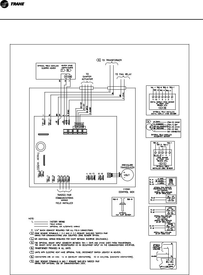
•Check the supply voltage at TB1. Proper polarity must be maintained. TB1-1 is the hot side (+) and TB1-2 is the ground side (-) of the 24VAC input. Refer to Figure 2, p. 17 and Figure 3, p. 18 for the VAV VV550 Controller terminal locations. The VAV VV550 Controller cannot be powered from a common 24VAC transformer that is supplying power to a device containing a full-wave rectifier bridge in its power supply. The acceptable voltage is 18 to 32 VAC (24VAC cataloged). However, voltages at either extreme may result in increased system instability.
•Verify that communications wiring has properly been terminated at TB2-1 (+) and TB2-2 (-). Polarity is not important on the communications link.
•Verify that the zone sensor connections are correct as detailed in this IOP.
•If heat has been added to unit, verify that the proper output connections have been made as detailed in this IOP.
•Verify that the tubing is properly connected to the transducer.
14 |
VAV-SVP01A-EN |

VAV Start Up/Check Out Procedure
VV550 Power Wiring
Power Requirements
WARNING
Hazardous Voltage!
Disconnect all electric power, including remote disconnects before servicing. Follow proper lockout/tagout procedures to ensure the power can not be inadvertently energized. Failure to disconnect power before servicing could result in death or serious injury.
WARNING
Electrocution and Fire Hazards with Improperly Installed and Grounded Field Wiring!
Improperly installed and grounded field wiring poses FIRE & ELECTROCUTION hazards. To avoid these hazards, you MUST follow requirements for field wiring installation and grounding as described in the National Electrical Codes (NEC) and your local/state electrical codes. All field wiring MUST be performed by qualified personnel. Failure to follow these requirements could result in death or serious injury.
Notice:
Use Copper Conductors Only!
Unit terminals are not designed to accept other types of conductors. Failure to use copper conductors could result in equipment damage.
Use at least 16 AWG for power wiring and connect to terminal TB1-1 (+) and TB1-2 (-). 24VAC is required to power the VAV VV550 Controller and has an acceptable voltage tolerance of 18 to 32 VAC. Refer to Figure 2, p. 17 and Figure 3, p. 18 for the VAV VV550 Controller terminal locations. Replace the VAV VV550 Controller control box cover after field wiring to prevent any electromagnetic interference.
Note: A dedicated 24VAC, 50VA NEC class 2 transformer is recommended to power the VAV VV550 Controller. When powering multiple VAV VV550 Controllers from one transformer, polarity must be maintained. Terminal TB1-1 is designated positive (+) and terminal TB1-2 is negative (-) to the unit casing ground
The power consumption for cooling only Series F Models (VariTrac and VariTrane) is 12 VA (4 VA for the air valve/actuator and 8 VA for the VV550 control board). To determine the total VAV VV550 Controller power requirement, add the power consumption per stage to the circuit board power requirement. For example, a Series F unit containing magnetic contactors with three stages of reheat would consume 42 VA.
Table 3. VA for factory-installed components
Style |
Volt Amps |
|
|
F - Style Actuator |
4 VA |
|
|
Air Valve Actuator C through E Style |
12 VA |
|
|
Varitrac Actuator |
3 VA |
|
|
Fan Power Fan Output |
6 VA |
|
|
Hot Water Proportional |
4 VA |
|
|
Hot Water 2 Position |
6.5 VA |
|
|
Electric Heater Magnetic Contactor |
10 VA |
|
|
Electric Heater Mercury Contactor |
12 VA |
|
|
VAV-SVP01A-EN |
15 |
VAV Start Up/Check Out Procedure
Note: VariTrane and VariTrac cooling only Series D and E models consume 20 VA (12 VA for the actuator and 8 VA for the board). The heating output ratings remain the same.
Refer to Figure 2, p. 17 and Figure 3, p. 18 for VAV VV550 Controller terminal locations and Figure 59, p. 107 through Figure 66, p. 114 for wiring of output devices.
Light Emitting Diode (LED) Operations
Green Status LED
The green status LED is typically used to indicate whether or not the controller is powered On (24VAC). This is the only LED under direct software control. The green status LED is Off when you press the Test button. The green status LED blinks during manual output testing. Table 4, p. 16 shows and describes the green status LED activity.
Table 4. Green status LED activity
Green status LED activity |
Description |
|
|
|
|
On |
Power On, normal operation |
|
|
|
|
Off |
One of the following: Power Off Controller failure Test button pressed |
|
|
|
|
Blinking for 10 seconds, |
Wink mode(a) |
|
0.25 seconds Off; 0.25 seconds On |
||
One blink continuously, |
The controller is in the manual output test mode and no output-override unit |
|
0.25 seconds Off; 2.25 seconds On |
diagnostic2 conditions |
|
|
|
|
Two blinks continuously, |
The controller is in the manual output test mode and one or more output- |
|
0.25 seconds Off; 0.25 seconds On |
||
override unit diagnostic(b) conditions exist |
||
0.25 seconds Off; 1.75 seconds On |
|
(a)The wink feature enables you to identify a controller. By sending a request from the Rover service tool, you can request the controller to wink.
(b)See the diagnostic topic in this guide for a complete list of output override diagnostics.
16 |
VAV-SVP01A-EN |

VAV Start Up/Check Out Procedure
Figure 2. VV550 single duct control diagram
VAV-SVP01A-EN |
17 |
VAV Start Up/Check Out Procedure
Figure 3. VV550 fan-powered control diagram
18 |
VAV-SVP01A-EN |

VAV Start Up/Check Out Procedure
Communication Wiring
WARNING
Hazardous Voltage!
Disconnect all electric power, including remote disconnects before servicing. Follow proper lockout/tagout procedures to ensure the power can not be inadvertently energized. Failure to disconnect power before servicing could result in death or serious injury.
WARNING
Electrocution and Fire Hazards with Improperly Installed and Grounded Field Wiring!
Improperly installed and grounded field wiring poses FIRE & ELECTROCUTION hazards. To avoid these hazards, you MUST follow requirements for field wiring installation and grounding as described in the National Electrical Codes (NEC) and your local/state electrical codes. All field wiring MUST be performed by qualified personnel.
Failure to follow these requirements could result in death or serious injury.
Communication Link Wiring
•Use 22 AWG Level 4 unshielded communication wire for most Comm5 installations.
•Limit Comm5 links to 4,500 ft and 60 devices maximum (without a repeater).
•Use the following termination resistors on all links:
•105 Ω at each end for Level 4 wire
•Use daisy chain topology.
•Limit zone sensor communication stubs to 8 per link, 50 ft each maximum.
•Use one repeater for an additional 4,500 ft, 60 devices, and 8 communication stubs.
Recommended Wiring Practices
To ensure proper network communication, follow these recommended wiring and planning guidelines when installing communication wire:
•All wiring must comply with the National Electrical Code (NEC) and local codes.
•Although Comm5 does not require polarity sensitivity, Trane recommends keeping polarity consistent throughout the site.
•Make sure that 24VAC power supplies are consistent in how they are grounded. Avoid sharing 24VAC between Comm5 controllers.
•Avoid over tightening cable ties and other forms of cable wraps. This can damage the wires inside the cable.
•Do not run Comm5 cable alongside or in the same conduit as 24VAC power. This includes the conductors running from triac-type inputs.
•In open plenums, avoid running wire near lighting ballasts, especially those using 277 Vac.
•Use a daisy chain configuration.
•Use termination resistors as described in "Termination resistance placement for Comm5 links"
•Insulate termination-resistor leads.
•Use only one type of communication wire; do not mix different types
VAV-SVP01A-EN |
19 |
VAV Start Up/Check Out Procedure
Wiring requirements
The recommended Comm5 communication-link wiring is 22 AWG, Level 4, twisted-pair wire. See Table 5, p. 20 "Specifications for Level 4-compliant cables". The wire can be either shielded or unshielded. However, unshielded wire is recommended for most installations.
The maximum wire length for Comm5 communication links is 4,500 ft (1,400 m). Comm5 communication-link wiring must be installed in a daisy-chain configuration (Figure 4, p. 21 and Figure 5, p. 22).
Table 5. Cable specifications
Specification |
|
Value |
|
|
|
|
|
dc resistance |
|
|
|
(Maximum resistance of a single copper conductor regardless of whether or not it is solid or stranded and regardless |
18.0 Ω/1,000 ft 20°C |
||
of whether or not it is metal coated.) |
|
|
|
|
|
|
|
dc resistance unbalance (maximum) |
|
5% |
|
|
|
|
|
Mutual capacitance of a pair (maximum) |
|
17 pF/foot |
|
|
|
|
|
Pair-to-ground unbalance (maximum) |
|
1,000 pF/foot/1,000 ft |
|
|
|
|
|
Characteristic impedence |
772 kHz |
102 Ω ± 15% |
|
|
|
|
|
|
1.0 MHz |
100 Ω ± 15% |
|
|
|
|
|
|
4.0 MHz |
100 Ω ± 15% |
|
|
|
|
|
|
8.0 MHz |
100 Ω ± 15% |
|
|
|
|
|
|
10.0 MHz |
100 Ω ± 15% |
|
|
|
|
|
|
16.0 MHz |
100 Ω ± 15% |
|
|
|
|
|
|
20.0 MHz |
100 Ω ± 15% |
|
|
|
|
|
Attenuation (maximum dB/1,000 ft at 20°C) |
772 kHz |
4.5 dB/1,000 ft at 20°C |
|
|
|
|
|
|
1.0 MHz |
5.5 dB/1,000 ft at 20°C |
|
|
|
|
|
|
4.0 MHz |
11.0 dB/1,000 ft at 20°C |
|
|
|
|
|
|
8.0 MHz |
15.0 dB/1,000 ft at 20°C |
|
|
|
|
|
|
10.0 MHz |
17.0 dB/1,000 ft at 20°C |
|
|
|
|
|
Worst-pair near-end crosstalk (minimum) |
772 kHz |
58 dB |
|
(Values shown are for information only. The minimum NEXT coupling loss for any pair combination at |
|
|
|
1.0 MHz |
56 dB |
||
room temperature is to be greater than the value determined using the formula NEXT (FMHz)>NEXT |
|||
|
|
||
4.0 MHz |
47 dB |
||
(0.772)-15log10 (FMHz/0.72) for all frequencies in the range of 0.772 MHz-20 MHz for a length of 1,000 |
|||
ft.) |
|
|
|
8.0 MHz |
42 dB |
||
|
|||
|
|
|
|
|
10.0 MHz |
41 dB |
|
|
|
|
|
|
16.0 MHz |
38 dB |
|
|
|
|
|
|
20.0 MHz |
36 dB |
|
|
|
|
|
dc resistance unbalance (maximum) |
|
5% |
|
|
|
|
|
20 |
VAV-SVP01A-EN |
VAV Start Up/Check Out Procedure
Figure 4. Daisy chain configuration
Termination Resistor
Ω
Ω
Note: Use 105 Ω, 1%, 1/4 W for 22 AWG, Level 4.
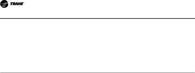
Comm5 Link Repeater
A Comm5 link repeater regenerates the signal on a Comm5 link. The configurations on either side of the repeater should be daisy chain. Both link segments require proper termination (Figure 5, p. 22).
Link repeater requirements.
A link repeater is required when:
•The total wire length is greater than the maximum wire run length of 4,500 ft (1,400 m).
•More than 60 devices are connected to a link-This total does not include the BCU, the link repeater, and the temporary use of a service tool on the same link.
•More than eight zone sensor communication stubs (maximum 50 ft) are required on a Comm5 link
Link repeater connections.
The recommended shield connections are shown in Figure 6, p. 22. Use these connections for instances where shielded communication wire is used. For an example of using a repeater to create an extended daisy chain configuration, see Figure 5, p. 22.
Follow these guidelines when using a repeater:
•Read the Comm5 repeater installation (3270 3285) information that comes with the link repeater.
•For information about terminating daisy chain configurations, see "Termination resistance placement for Comm5 links" onFigure 4, p. 21.
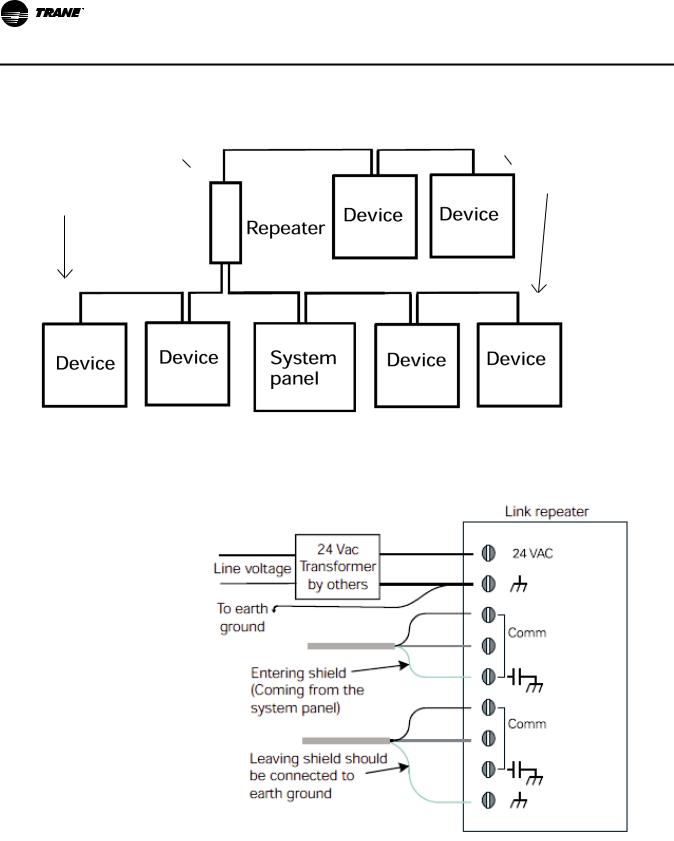
•Connect shield-drain wires entering the repeater to a terminal marked with a capacitor symbol. The entering shield-drain wire must be connected to earth ground at the system panel.
•Connect shield-drain wires leaving the repeater to the repeater terminal marked with an earth ground symbol.
VAV-SVP01A-EN |
21 |
VAV Start Up/Check Out Procedure
Figure 5. Alternate daisy chain configuration
Termination  Ω
Ω
Ω  Termination
Resistors
Resistors
Ω |
Ω |
Notes:
1.Maximum wire length for the entire configuration is 4,500 ft (1,400 m).
2.Comm5 wire length limitations can be extended through the use of a link repeater, see “Comm5 physical link repeater.”
Figure 6. Comm5 shield repeater connection
22 |
VAV-SVP01A-EN |

VAV Start Up/Check Out Procedure
Yellow Comm LED
The yellow Comm5 LED blinks whenever another controller is transmitting. However, the yellow Comm5 LED does not blink when the controller is transmitting data. The yellow Comm5 LED cannot distinguish between messages meant for the controller and messages that the controller ignores. Table 6, p. 23 shows and describes the yellow Comm LED activity.
Table 6. Yellow comm LED activity
Yellow Comm LED activity |
Description |
|
|
LED Off continuously |
The controller is not detecting communication. (Normal for stand-alone applications.) |
|
|
LED blinks or flickers |
The controller detects communication. (Normal for communicating applications, including data sharing.) |
|
|
LED On continuously |
Abnormal condition or extremely high traffic on the link. |
|
|
Table 7. Red service LED activity
Red service LED activity |
Description |
|
|
|
|
LED is Off continuously after power is applied to the controller. |
Normal operation |
|
|
|
|
LED is On continuously, even when power is first applied to the |
Someone is pressing the Service push button or the controller failed. |
|
controller. |
||
|
||
|
|
|
LED flashes about once every two seconds. |
Uninstalled (normal controller mode). Use the Rover service tool to restore |
|
|
the unit to normal operation. Refer to the Rover product literature for more |
|
|
information. |
|
|
|
Service Push Button
Important: If the Service button is held down for more than 15 seconds, the controller will uninstall itself from the Comm5 network. The red service LED flashing approximately once two every seconds indicates this mode (see Red service LED above). Use the Rover service tool to restore the unit to normal operation. Refer the Rover product literature for more information.
The Service push button can be used, as one of several methods, to install the controller in a communication network. Refer to the Rover service tool product literature EMTX-SVX01*-EN for more information.
Space temperature controller Analog Inputs
Zone Sensor Hardwired Option. Depending on the zone sensor options used, a maximum of five wires may be required to run from the VAV VV550 Controller to the zone sensor. The zone sensor options are:
•Zone sensor only (2 wires) - Part Number X13511528010.
•Sensor with night set backPart Number X13511530010.
•Zone sensor with external adjustable - Part Number X13511529010.
•Zone sensor with external adjustable night set back, timed override (TOV) on/cancel button -
Part Number X13511527010.
•Digital zone sensor - Part Number X13511530010
•Communications jack - Part Number X13651467020 (for one box of 12)
Note: All wiring from the zone sensor to the Com link must be twisted shielded pair wiring.
VAV-SVP01A-EN |
23 |
VAV Start Up/Check Out Procedure
Zone Sensor Wireless Option (Wireless Zone Sensor). Receiver is used to receive a signal from the wireless zone sensor and can be factory installedPart Number X13790855010. The wiring harness connects the receiver to the VAV VV550 Controller - Part Number X19051672010.
Zone Sensor Wireless Option (Zone Sensor). The wireless zone sensor with night setback timed override (TOV) on/cancel button. Also can be ordered for Celsius and Fahrenheit setpoint adjustment - Part Number X13790492010 (F), Digital Display wireless zone sensorPart Number X13790822010
Zone Sensor Wiring
Location and Mounting. A zone sensor in each control zone should be located in the most critical area of the zone. Sensors should not be mounted in direct sunlight or in the area's supply air stream. Subdivision of the zone may be necessary for adequate control and comfort. Avoid mounting zone sensors in areas subject to the following:
•Drafts or "dead spots" behind doors or corners.
•Hot or cold air ducts.
•Radiant heat from the sun or appliances.
•Concealed pipes or chimneys.
•Unheated or uncooled surfaces behind the sensor such as outside walls.
•Air flows from adjacent zones or other units.
Wiring. Each unit must be controlled by a zone sensor that is designated specifically for use with the VAV VV550 Controller. Field wiring for the zone sensors must meet the following requirements:
•Must be 14 to 18 AWG.
•Refer to Figure 2, p. 17 and Figure 3, p. 18 and the sensor instructions for terminal connections.
•If local codes require enclosed conductors, the zone sensor wires should be installed in conduit. Do not route zone sensor wires in conduit with 24VAC or other high power conducting wires.
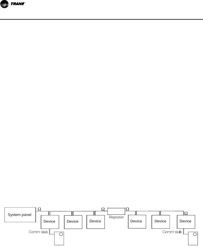
Zone sensor comm stubs. For the most reliable communications, limit the number of zone sensor communication stubs to 8 per Comm5 link unless using a repeater then it is 16 stubs. Each stub should not exceed 50 feet. Exceeding these limits increases the likelihood of communication problems. Connect Communication wire to terminals TB2-5 and TB2-6 on VV550 controller and to comm. Jack in zone sensor
Figure 7. Communication stubs used with a repeater
Notes:
1.Maximum wire length on either side of the repeater is 4,500 ft (1,400 m).
2.The link repeater is limited to 60 devices on either side of the link.
3.Place termination resistors at the end of the link. Use a 105 X resistor at each end of the link for Level 4 wire
24 |
VAV-SVP01A-EN |
VAV Start Up/Check Out Procedure
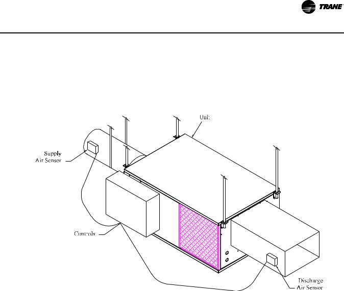
Auxiliary Duct Temperature Sensor
The typical mounting position of the auxiliary sensor is upstream of the VAV unit and connected into the DDC controller at TB3-5 and TB3-6. Comm5 could be mounted downstream of the reheat for improved diagnostics (Figure 8, p. 25). Refer to Controller Diagrams Figure 2, p. 17 and Figure 3, p. 18 for the VAV VV550 Controller terminal locations.
Figure 8. Duct temperature sensors: upstream/downstream
Binary Input Wiring
Each VAV VV550 Controller provides one binary input. On the VV550 factory-installed controller, the binary input configuration is set up at the factory. The binary input can be configured with Rover service tool as occupancy or generic or not used. The input associates 0 Vac with open contacts and 24VAC with closed contacts. It is activated by a dry contact switch closure.
•Must be 14 to 18 AWG.
•Refer to Figure 2, p. 17 and Figure 3, p. 18 and the sensor instructions for terminal connections.
Occupancy Binary Input. The occupancy binary input can be configured as NO or NC. Occupied is the normal state. It is also the initial state at power-up and after a reset. Unoccupied is the other state. If the binary input is configured as generic, the default occupancy mode is occupied.
Generic Binary Input. The generic binary input can be configured as NO or NC. Normal state is inactive and is also the initial state at power-up and after a reset. Active is the other state.
Not Used Input. When no device is connected to the input, configure the controller input as not used.
Binary Outputs Wiring
Binary outputs that are required for unit operation are factory wired and commissioned.
VAV-SVP01A-EN |
25 |

VAV Start Up/Check Out Procedure
Ventilation Flow control
See Auxiliary Duct Temperature Sensor wiring on Space temperature controller Analog Inputs
Note: If heat is installed Auxilary sensor will be located at the discharge of the VAV unit.
Flow Tracking Control
Two controls are used in Flow tracking controller. One is configured with the Space temperature control program and the other controller will be set up as flow tracking controller and it will not need any input or output device connected to the controller. See Operation section for details.
26 |
VAV-SVP01A-EN |
VAV Start Up/Check Out Procedure
Wireless Zone Sensor
Overview
The Trane Wireless Zone Sensor set includes a sensor and a receiver that work together to provide the same functions as the equivalent Trane wired sensor, such as the standard 10 k temperature input (with the exception of the communication jack). No further software or hardware is necessary for site evaluation, installation, or maintenance.
The sensor transmits the zone temperature, all zone temperature setpoint functions, timed override Occupied (On) and timed override Unoccupied (Cancel) information to the receiver. The receiver electrically reproduces the zone temperature resistance, all zone temperature setpoint function resistances, and timed override On and timed override Cancel information as sent by the sensor.
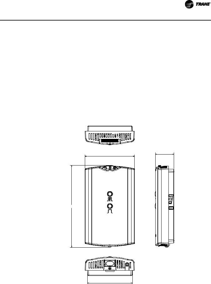
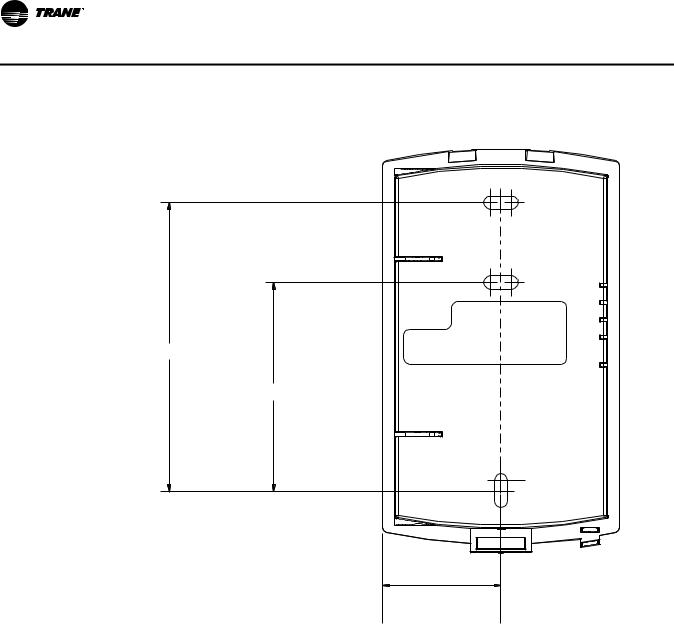
Dimensional Diagrams
See Figure 9, p. 27 and Figure 10, p. 28 for dimensions of the Wireless Zone Sensor set. The dimensions are the same for both the sensor and the receiver.
Figure 9. Outside dimensions for sensor
1.08 in (2.75 cm)
2.90 in (7.35 cm)
4.78 in (12.14 cm)
2.62 in (6.65 cm)
Note: The dimensions are the same for both the sensor and the receiver.
VAV-SVP01A-EN |
27 |
VAV Start Up/Check Out Procedure
Figure 10. Mounting hole dimensions for sensor
3.27 in (8.30 cm)
2.36 in (6.00 cm)
1.34 in (3.41 cm) |
Note: The dimensions are the same for both the sensor and the receiver.
Setting the Address, Mounting, Wiring, and Associating the Receiver and Sensor
The following procedure list shows the recommended order for installation:
•Choosing a Location for Mounting the Sensor.
•Setting the Rotary Address Switches on the Receiver and on the Sensor.
•Replacing and Securing the Receiver Cover.
•Powering the Sensor and Associating the Sensor to the Receiver.
•Applying Power to the Receiver.
•Testing Signal and Battery Strength.
•Disassociation.
28 |
VAV-SVP01A-EN |

VAV Start Up/Check Out Procedure
Choosing a Location for Mounting the Sensor
Placement of the receiver and the sensor set is critical to proper operation. In most installations, distance is not the limiting factor for proper radio signal quality. It is more greatly affected by walls, barriers, and general clutter. For best radio transmission range and reliability, wherever possible, mount the receiver and sensor in line of sight. Try to minimize the number of barriers between the pair of devices. In general, sheetrock walls and ceiling tiles offer little restriction to the propagation of the radio signal throughout the building; concrete or metal barriers offer the most restriction. The transmission range for the sensor is as follows:
•Open range: 2,500 ft (762 m) (packet error rate = 2%)
•Usable range: 200 ft (61 m)
•Typical range: 75 ft (23 m)
Ambient considerations
Avoid locations that are outside the operating temperature and humidity range.
Location Considerations for the Sensor
When selecting a location for the sensor, consider both thermal and radio transmission characteristics of the location.
Thermal considerations
•Avoid areas of direct sunlight.
•Avoid areas in the direct air stream of air diffusers.
•Avoid exterior walls and other walls that have a temperature differential between their two sides.
•Avoid areas close to sources of heat such as sunlight, appliances, or other equipment.
•Avoid drafty areas.
•Avoid dead spots behind doors, projection screens, or corners.
Radio transmission considerations
•Avoid metal barriers between the sensor and receiver, such as plastered walls with metal lathe. They will decrease radio signal quality.
•Avoid placing the sensor inside metal enclosures.
•Avoid radio transmissions through thick, solid concrete walls.
Setting the Rotary Address Switches on the Receiver and the Sensor
Note: To expedite the installation and association process, set the addresses before applying power to the receiver.
The process of establishing communication between the receiver and sensor is referred to as association. The receiver and the sensor must have their rotary switches set to the same address in order to enable communication between the two devices (see Figure 11, p. 30). Important limitations are as follows:
•Only one associated receiver/sensor set can communicate within the reception range of the wireless system.
•It is not possible to associate more than one sensor to a receiver, nor is it possible to associate more than one receiver to a sensor.
VAV-SVP01A-EN |
29 |
VAV Start Up/Check Out Procedure
Figure 11. Setting the rotary address switches on the receiver and the sensor
Do not remove the insulation strip yet.
WIRELESS |
! |
INSTALL |
|
LED4 |
LED1 |
|
|
|
|
|
|
|
|
|
|
|
LED1 |
|
|
|
|
|
|
|
|
|||||
|
|
|
|
|
|
|
|
|||||
|
|
|
|
|
|
|
|
|
S4 |
|||
LED2 |
|
|
|
|
|
|
|
|
|
|
|
LED2 |
LED3 |
|
|
|
|
|
|
|
|
|
|
|
LED3 |
SIGNAL |
S1 |
S2 |
S3 |
|
|
|
|
|
|
|
SIGNAL |
|
|
|
|
|
|
|
|
||||||
LED5 |
ADDRESS |
|
|
|
|
|
|
|
|
|
LED5 |
|
|
|
|
|
|
|
|
|
|
|
|||
POWER |
|
C33 |
C34 |
|
|
|
|
|
BATTERY |
|||
|
|
J1 |
|
|
|
|
|
STATUS |
||||
|
|
HEATING SET |
|
|
|
|
|
|
|
|
|
|
|
S5 |
FAN/SYSTEM |
|
|
|
|
|
|
C35 |
|||
S5 |
SETPOINT |
|
|
|
|
|
|
|||||
|
ZONE |
|
|
|
|
|
|
R77 |
||||
|
GND |
|
|
|
|
|
|
|||||
|
24VAC/DC |
|
|
|
|
|
|
|
|
|
|
|
|
GND |
|
|
|
|
|
|
|
|
|
|
|
|
COMM + |
|
|
|
|
|
|
|
|
|
|
|
|
COMM - |
|
|
|
|
|
|
|
|
|
|
|
|
|
B1 + |
|
Pb |
|
|
Pb-FREE |
|
S1 |
S3 |
|
S2 |
LED4 |
|
ADDRESS |
||
STATUS
S4
WIRELESS
INSTALL
Setting the Receiver Address
1.Using a small screwdriver, set the three rotary address switches (locations S1, S2, S3) on the receiver (Figure 11, p. 30) to an address between 001 and 999.
Note: Do not use 000 as an address for installation. If you set the receiver address to 000, it will:
–Return the receiver outputs to their factory defaults indefinitely (zone temperature and setpoint outputs: 72.5°F [22.5°C]).
–Remove all association knowledge.
–Make the receiver unable to associate with a sensor.
•Read the switches from left to right in the order in which they are numbered (S1, S2, S3).
•Zero is at the nine o'clock position.
2.Make a notation of the address and location of the receiver.
Setting the Sensor Address
1.Using a small screwdriver, set the three rotary address switches (locations S1, S2, S3) on the sensor (Figure 11, p. 30) to the same address used for the receiver it is to be associated with.
2.Make a notation of the address and location where this sensor is to be mounted.
Note: Do not use 000 as an address for installation. If you set the address to 000, it will:
–Remove all association knowledge.
–Revert to a low-power hibernation mode.
–Send a disassociation request to the receiver. If the sensor and receiver are associated and communicating at the time the sensor is set to 000 and the Test button is pressed, the receiver will also become unassociated and will be available for re-association.
•Read the switches from left to right in the order in which they are numbered (S1, S2, S3).
•Zero is at the 9 o'clock position.
30 |
VAV-SVP01A-EN |
Loading...