


 Loading...
Installation, Operation,
and Maintenance
VAV-UCM 4.2
 SAFETY WARNING
Only qualified personnel should install and service the equipment. The installation, starting up, and servicing of heating, ventilating, and airconditioning equipment can be hazardous and requires specific knowledge and training. Improperly installed, adjusted or altered equipment by an unqualified person could result in death or serious injury. When working on the equipment, observe all precautions in the literature and on the tags, stickers, and labels that are attached to the equipment.
March 2014 |
VAV-SVX01D-EN |
Introduction
Read this manual thoroughly before operating or servicing this unit.
Warnings, Cautions, and Notices
Safety advisories appear throughout this manual as required.Your personal safety and the proper operation of this machine depend upon the strict observance of these precautions.
The three types of advisories are defined as follows:
 WARNING
 CAUTIONs
NOTICE:
Indicates a potentially hazardous situation which, if not avoided, could result in death or serious injury.
Indicates a potentially hazardous situation which, if not avoided, could result in minor or moderate injury. It could also be used to alert against unsafe practices.
Indicates a situation that could result in equipment or property-damage only accidents.
Important Environmental Concerns
Scientific research has shown that certain man-made chemicals can affect the earth’s naturally occurring stratospheric ozone layer when released to the atmosphere. In particular, several of the identified chemicals that may affect the ozone layer are refrigerants that contain Chlorine, Fluorine and Carbon (CFCs) and those containing Hydrogen, Chlorine, Fluorine and Carbon (HCFCs). Not all refrigerants containing these compounds have the same potential impact to the environment.Trane advocates the responsible handling of all refrigerants-including industry replacements for CFCs such as HCFCs and HFCs.
Important Responsible Refrigerant Practices
Trane believes that responsible refrigerant practices are important to the environment, our customers, and the air conditioning industry. All technicians who handle refrigerants must be certified.The Federal Clean Air Act (Section 608) sets forth the requirements for handling, reclaiming, recovering and recycling of certain refrigerants and the equipment that is used in these service procedures. In addition, some states or municipalities may have additional requirements that must also be adhered to for responsible management of refrigerants. Know the applicable laws and follow them.
 WARNING
Proper Field Wiring and Grounding
Required!
Failure to follow code could result in death or serious injury. All field wiring MUST be performed by qualified personnel. Improperly installed and grounded field wiring poses FIRE and ELECTROCUTION hazards. To avoid these hazards, you MUST follow requirements for field wiring installation and grounding as described in NEC and your local/state electrical codes.
 WARNING
Personal Protective Equipment (PPE)
Required!
Installing/servicing this unit could result in exposure to electrical, mechanical and chemical hazards.
•Before installing/servicing this unit, technicians MUST put on all PPE required for the work being undertaken (Examples; cut resistant gloves/sleeves, butyl gloves, safety glasses, hard hat/bump cap, fall protection, electrical PPE and arc flash clothing). ALWAYS refer to appropriate Material Safety Data Sheets (MSDS)/Safety Data Sheets (SDS) and OSHA guidelines for proper PPE.
•When working with or around hazardous chemicals, ALWAYS refer to the appropriate MSDS/SDS and OSHA/GHS (Global Harmonized System of Classification and Labelling of Chemicals) guidelines for information on allowable personal exposure levels, proper respiratory protection and handling instructions.
•If there is a risk of energized electrical contact, arc, or
flash, technicians MUST put on all PPE in accordance with OSHA, NFPA 70E, or other country-specific requirements for arc flash protection, PRIOR to servicing the unit. NEVER PERFORM ANY SWITCHING, DISCONNECTING, OR VOLTAGE TESTING WITHOUT PROPER ELECTRICAL PPE AND ARC FLASH CLOTHING. ENSURE ELECTRICAL METERS AND EQUIPMENT ARE PROPERLY RATED FOR INTENDED VOLTAGE.
Failure to follow instructions could result in death or serious injury.
© 2014Trane All rights reserved |
VAV-SVX01D-EN |

Introduction
Copyright
This document and the information in it are the property of Trane, and may not be used or reproduced in whole or in part without written permission.Trane reserves the right to revise this publication at any time, and to make changes to its content without obligation to notify any person of such revision or change.
Trademarks
VariTrac, VariTrane,Trane and theTrane logo are trademarks or registered trademarks ofTrane in the United States and other countries.Trane is a business of Ingersoll Rand. All trademarks referenced in this document are the trademarks of their respective owners.
Revision History
VAV-SVX01D-EN
Updated board photo and part number (BRD04939 replaced BRD02806).
VAV-SVX01D-EN |
3 |

Table of Contents |
|
Introduction . . . . . . . . . . . . . . . . . . . . . . . . . . . . |
. 2 |
Warnings, Cautions, and Notices . . . . . . . . |
2 |
Important Environmental Concerns . . . . . 2 |
|
Important Responsible Refrigerant |
|
Practices . . . . . . . . . . . . . . . . . . . . . . . . . . . |
2 |
General Information . . . . . . . . . . . . . . . . . . . . . |
6 |
Overview of Manual . . . . . . . . . . . . . . . . . . . |
6 |
Chapter Overview . . . . . . . . . . . . . . . . . . . . . |
6 |
Unit Control Module 4.2 (UCM 4.2) . . . . . . . |
6 |
Specifications . . . . . . . . . . . . . . . . . . . . . . . |
6 |
UCM 4.2 Enhancements . . . . . . . . . . . . . . . |
6 |
UCM 4.2 Features . . . . . . . . . . . . . . . . . . . . |
7 |
Shipping . . . . . . . . . . . . . . . . . . . . . . . . . . . |
8 |
Storage . . . . . . . . . . . . . . . . . . . . . . . . . . . . |
8 |
VAV Start Up/Check Out Procedure . . . . . . . . |
9 |
Chapter Overview . . . . . . . . . . . . . . . . . . . . . |
9 |
UCM 4.2 Pre-Power Check-Out . . . . . . . . . . |
9 |
Light Emitting Diode (LED) Operations . . . 9 |
|
Zone Sensor Check-out . . . . . . . . . . . . . . . . |
10 |
UCM 4.2 Installation and Wiring . . . . . . . . . |
11 |
Chapter Overview . . . . . . . . . . . . . . . . . . . . |
11 |
UCM 4.2 Power Wiring . . . . . . . . . . . . . . . . |
11 |
Power Requirements . . . . . . . . . . . . . . . . |
11 |
Zone Sensor Wiring . . . . . . . . . . . . . . . . . . . |
11 |
Location and Mounting . . . . . . . . . . . . . . |
11 |
Wiring . . . . . . . . . . . . . . . . . . . . . . . . . . . . |
11 |
Multiple UCM’s Per Zone Sensor . . . . . . |
12 |
Multiple UCM’s per Auxiliary Duct |
|
Temperature Sensor . . . . . . . . . . . . . . . . |
12 |
Zone Sensor Hardwired Option . . . . . . . |
12 |
Zone Sensor Wireless Option . . . . . . . . . |
12 |
Communication Wiring . . . . . . . . . . . . . . . . |
12 |
Communication Link Wiring . . . . . . . . . . |
12 |
DIP Switch Settings . . . . . . . . . . . . . . . . . . . |
13 |
Wireless Zone Sensor . . . . . . . . . . . . . . . . . . . |
17 |
Overview . . . . . . . . . . . . . . . . . . . . . . . . . . . . |
17 |
Dimensional Diagrams . . . . . . . . . . . . . . . . |
17 |
Setting the Address, Mounting, Wiring, |
|
and Associating the Receiver and Sensor |
18 |
Choosing a Location for Mounting |
|
the Sensor . . . . . . . . . . . . . . . . . . . . . . |
. . . .18 |
Setting the Rotary Address Switches |
|
on the Receiver and the Sensor . . . . |
. . . .19 |
Factory Wiring of the Receiver to |
|
the VAV UCM . . . . . . . . . . . . . . . . . . . |
. . . .20 |
Replacing and Securing the |
|
Receiver Cover . . . . . . . . . . . . . . . . . . |
. . . .22 |
Applying Power to the Receiver . . . . |
. . . .22 |
Powering the Sensor and Associating |
|
the Sensor to the Receiver . . . . . . . . |
. . . .23 |
Testing Signal and Battery Strength |
. . . .23 |
Disassociation . . . . . . . . . . . . . . . . . . |
. . . .23 |
UCM Programming and Operation . . . . |
. . . .24 |
Chapter Overview . . . . . . . . . . . . . . . . . |
. . . .24 |
Accessing Rover/Comm4 . . . . . . . . . . . |
. . . .24 |
Rover Overview . . . . . . . . . . . . . . . . . |
. . . .24 |
Laptop Requirements and Complete |
|
Connection Instructions . . . . . . . . . . . |
. . . .24 |
UCM Home Tabs: At a Glance . . . . . . . |
. . . .26 |
Status Tab . . . . . . . . . . . . . . . . . . . . . . |
. . . .27 |
Setpoints Tab . . . . . . . . . . . . . . . . . . . |
. . . .27 |
Wireless Tab . . . . . . . . . . . . . . . . . . . . |
. . . .28 |
Advanced Configuration Tab . . . . . . |
. . . .28 |
UCM Home Tabs: Instructions . . . . . . . |
. . . .28 |
Configuration . . . . . . . . . . . . . . . . . . . |
. . . .28 |
Setpoints Tab . . . . . . . . . . . . . . . . . . . |
. . . .28 |
Setup Tab . . . . . . . . . . . . . . . . . . . . . . |
. . . .30 |
Wireless Tab . . . . . . . . . . . . . . . . . . . . |
. . . .33 |
Advanced Configuration Tab . . . . . . |
. . . .34 |
Entering and Exiting the Service Mode . . .35 |
|
Overriding VAVs . . . . . . . . . . . . . . . . . . |
. . . .35 |
Resetting Diagnostics . . . . . . . . . . . . . . |
. . . .35 |
Saving VAV Program . . . . . . . . . . . . . . |
. . . .35 |
Downloading Program Files from |
|
PC to DDC UCM 4.2 . . . . . . . . . . . . . . |
. . . .36 |
Sequence of Operations . . . . . . . . . . . . . . |
. . . .38 |
Chapter Overview . . . . . . . . . . . . . . . . . |
. . . .38 |
Single Duct Units . . . . . . . . . . . . . . . . . . |
. . . .38 |
Override Conditions (Single Duct) . . . |
. . . .38 |
Fan-Powered Units . . . . . . . . . . . . . . . . |
. . . .39 |
4 |
VAV-SVX01D-EN |

Parallel Fan-Powered Units . . . . . . . . . . . . 39
Occupied Units . . . . . . . . . . . . . . . . . . . . . 39
Override Conditions (Parallel Fans) . . . . . 39
Series Fan-Powered Units . . . . . . . . . . . . . 40
Occupied Units . . . . . . . . . . . . . . . . . . . . . 40
Override Conditions (Series Fan) . . . . . . . 40
Zone Sensor Functions . . . . . . . . . . . . . . . . 40
Flow Sensor . . . . . . . . . . . . . . . . . . . . . . . . . 41
Failure Modes . . . . . . . . . . . . . . . . . . . . . . . . 41
Air and Water Balancing . . . . . . . . . . . . . . . . 42
Chapter Overview . . . . . . . . . . . . . . . . . . . . 42
Air Balancing . . . . . . . . . . . . . . . . . . . . . . . . 42
System Checkout . . . . . . . . . . . . . . . . . . . 42
System Setup . . . . . . . . . . . . . . . . . . . . . . 42
VAV Single Duct Unit Air Balancing . . . . 42
Water Balancing . . . . . . . . . . . . . . . . . . . . . . 44
Troubleshooting . . . . . . . . . . . . . . . . . . . . . . . . 45
Chapter Overview . . . . . . . . . . . . . . . . . . . . 45 Diagnostic Log . . . . . . . . . . . . . . . . . . . . . 45 Diagnostic Table . . . . . . . . . . . . . . . . . . . . 46 UCM Failure Procedures . . . . . . . . . . . . . 46 UCM Communication Loss Procedures . 47 Wired Zone Sensor Failure Procedures . 47 Wired Zone Setpoint Failure Procedures 48 Wireless Zone Sensor Failure Procedures 49 Airflow Failure Procedures . . . . . . . . . . . 51
Auxiliary Temperature Sensor Failure
Procedures . . . . . . . . . . . . . . . . . . . . . . . . 53
Auxiliary C02 Sensor Failure Procedures 53 VAV Damper Failure Procedures . . . . . . . 53 VAV Series Fan Failure Procedures . . . . 54 VAV Parallel Fan Failure Procedures . . . 54
VAV Electric Heat Stage(s) Failure
Procedures . . . . . . . . . . . . . . . . . . . . . . . . 56
VAV Proportional Hot water failure . . . . 56
Trane/Honeywell Proportional valve
check out procedures . . . . . . . . . . . . . . . . . 57 Cartridge Failure . . . . . . . . . . . . . . . . . . . . 57 Actuator Failure . . . . . . . . . . . . . . . . . . . . 57 VAV Two Position Hot water failure . . . . 57
Wiring Diagrams . . . . . . . . . . . . . . . . . . . . . .58
Appendix . . . . . . . . . . . . . . . . . . . . . . . . . . . . . . .66
VAV-SVX01D-EN |
5 |

General Information
Overview of Manual
Note: One copy of the document is shipped with VAV units that have UCM 4.2 DDC controllers and is customer property. It must be retained by the unit's maintenance personnel.
This booklet describes proper installation, operation, and maintenance procedures for delivered air systems. By carefully reviewing the information within this manual and following the instructions, the risk of improper operation and/or component damage will be minimized. Should equipment failure occur, contact a qualified service organization with qualified, experienced HVAC technicians to properly diagnose and repair this equipment.
Chapter Overview
This chapter contains information about the following:
•Unit Control Module 4.2 (UCM 4.2)
•Specifications
•UCM 4.2 Enhancements
•UCM 4.2 Features
•Shipping
•Storage
Unit Control Module 4.2 (UCM 4.2)
The UCM 4.2 is a microprocessor-based, Direct Digital Controller (DDC) for the (Variable Air Volume) VAV terminal unit. It contains the control logic to modulate the flow of supply air through theVAV terminal in response to the load requirements within the VAV zone.
The function of the UCM is to control theVAV terminal unit to vary the volumetric airflow rate to the zone. Units have been made with either pneumatic, analog electronic, or microprocessor controls (DDC VAV).This manual discusses only terminal units with Comm4 DDC/VAV controls. Factory installed DDC/VAV controls are available with all single duct terminal units, dual duct units, as well as parallel fan-powered and series fan-powered units.Two UCMs are required for dual duct units (one for the heating duct and one for the cooling duct).
The UCM modulates a VAV's damper blade based on a zone temperature, measured airflow, and airflow set points to continuously control conditioned air delivery to the space.The volume of incoming air is monitored and the damper adjusts to provide accurate control independent of the duct pressure.The damper modulates between operator airflow set points depending on space conditions. Additionally, fan and heat outputs may be energized depending on the application. Available inputs
include a twisted/shielded communication link, zone sensor, auxiliary temperature sensor (optional), CO2 Sensor (optional), and Occupy/Unoccupy Sensor (optional), and 24 VAC power.
Specifications
Power Requirements
The UCM 4.2 requires 24VAC, 50/60 Hz NEC Class 2 power. The UCM itself consumes 8 VA. Our factory installed devices draw from 3 to 12 VA.Typical values are 4 VA for a damper actuator, 10 to 12 VA for an electric heat contractor, and 6 VA for a fan relay.The NEC Class 2 transformer should be sized to handle the total VA of all devices.The binary outputs are rated at steady-state 12VA max.
Operating Environments - UCM 4.2
32° to 140°F (0° to 60°C), 10% to 90% relative humidity, noncondensing
Storage Environments - UCM 4.2
-40° to 150°F (-40° to 65.6°C), 10% to 90% relative humidity, non-condensing
Mounting
Typically, the UCM 4.2 is factory installed. However, UCM 4.2 is available with retrofit kits, in which case it must be field installed.
Tracer Summit and UCM 4.2 Communications
Link Wiring
Communications Link wiring must be 18 AWG twisted shielded pair wire. Each conductor must be stranded tinned copper.The maximum total wire length is 5,000 feet (1,524 m). See “UCM 4.2 Installation and Wiring,” p. 11 for further information about wire selection.
UCM 4.2 Enhancements
•The enhanced VAV UCM is backward compatible with VariTrane® D VAV boxes (VXXD and VXXE) VariTrac® dampers, and VariTrac II dampers.
•UCM 4.2 adds support for operation with VariTrane Series F valves (¼-turn blade dampers) via 90-second drive time.
•UCM 4.2 adds a second, C02 interfacing, mode of operation to the auxiliary analog input (TB3-5).This is a 1 to 10 volt DC input with a mapping of input voltage to C02 output data value of 200 parts per million (PPM) of C02 per volt.The use of this new auxiliary analog input as an interface to a C02 detector is mutually exclusive with the use of the input as auxiliary temperature input.Therefore, the use of the C02 interfacing mode of operation is not recommended for stand-alone applications requiring auto-changeover.
6 |
VAV-SVX01D-EN |
General Information
•UCM 4.2 adds a binary 24VAC, dry contact input. It can be configured either as a generic input or as an occupancy detector input.
•UCM 4.2 adds a VariTrac Bypass Damper mode of operation. In this mode, supply air temperature and supply air pressure is made available on the Comm4 link.The damper position is a Comm4-control parameter. A Comm4 configurable failsafe position was added.The supply air temperature uses a new "S" input (TB3-7).The use of this new input is mutually exclusive with the zone temp input (TB3-1).
•UCM 4.2 now assumes the hot water valve is closed after reset.This prevents a reset during hot water override from causing the valve to stop moving.This also changes the behavior after reset, when there is a reheat demand, the hot water valve now opens (from assumed closed position) to the desired reheat position.
•In a wireless system, the hard-wired sensor can now be configured as not present.The hard-wired sensor failures will not be reported as long as at least one wireless zone sensor is reporting valid temperature values.
Note: This is an older wireless system that has been obsoleted and not the one discussed in the wireless zone sensor section.
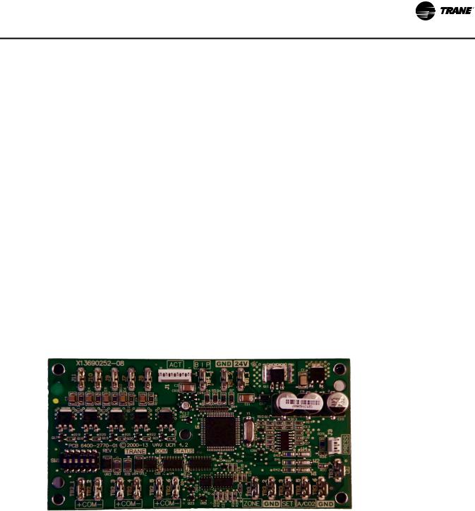
Figure 1. UCM 4.2 board layout
Zone Sensor, Auxiliary Sensor, and
Thumbwheel Set Point Calibration
If there is a discrepancy between a measured temperature and what the UCM reports, a calibration offset value can be edited in the UCM setup screen to correct the displayed value.
Flow Sensor Calibration
If there is a discrepancy between a measured flow and what the UCM reports, the measured value can be entered, which automatically calculates a calibration multiplier to correct the displayed value.
•For standalone units, series or parallel fan operation will use the unoccupied fan control when the local unoccupied request (** function) is received. In UCM
3.3and prior, the fan would operate as if occupied during local unoccupied request.
•UCM 4.2 adds a local minimum heating flow set point. The use of and value of this set point is configurable.
UCM 4.2 Backward Compatibility
UCM 4.2 can be used to replace UCM I, UCM II, and UCM III with no compatibility issues. However, if the communicating device (i.e. Command Unit I or Comfort Manager™ I) is a COM 3 device (1992 or earlier), then you will need an upgrade chip.The Comfort Manager chip upgrade is Kit 1511 and the Command Unit chip upgrade is Kit 1512.
UCM 4.2 Features
UCM Outputs
UCMTriac outputs for controlling a fan or reheat are rated at 12 VA each.
Wiring Diagram
Figure 3, p. 14 shows a typical wiring diagram for the redesigned UCM hardware.The new service part number is BRD04939.
Water Valve Override
Each UCM that has proportional or staged hot water heat outputs can be edited to override the water valve to its maximum position.
Ventilation Set Points and Ratio Calculation
Set point values needed for a space to satisfy indoor air quality requirements are provided. A resultant ventilation ratio can be used to calculate an air handler's outside air damper minimum position or other control strategies.
VAV-SVX01D-EN |
7 |

General Information
Water Heat Output Configuration
UCMs that have hot water heat outputs can be configured for normally open or normally closed.
Zone Sensor Functions
Zone sensor functions now include: air valve drive to maximum, use unoccupied set points, timed override, and cancel timed override.
Slaving of Zone Sensors
Up to three (3) UCM 4.2 may be connected to a single zone sensor.
Generic UCM Capability
UCM 4.2 can be configured to control non-Trane VAV boxes.
Shipping
Each VAV product and its service literature are shipped in the same package. When unpacking, make sure that the literature is not lost or discarded with the packing material. Visually inspect the individual components for obvious defects or damage. All components are thoroughly inspected before leaving the factory. Any claims for damage incurred during shipment must be filed with the carrier.
Storage
When any component of the VAV system and/or field installed accessories must be stored for a period of time prior to being installed, they must be protected from the elements.The storage location temperature should be between -40° to 150°F (-40° to 65.6°C) and the relative humidity should be 10% to 90%, non-condensing.
The warranty will not cover damage to the VAV system or controls due to negligence during storage. A controlled indoor environment must be used for storage.
8 |
VAV-SVX01D-EN |
VAV Start Up/Check Out Procedure
Chapter Overview
This chapter contains information about the following:
•Unit 4.2 Pre-Power Check-Out
•Light Emitting Diode (LED) Operations
•Zone Sensor Check-Out
UCM 4.2 Pre-Power Check-Out
 WARNING
Live Electrical Components!
During installation, testing, servicing and troubleshooting of this product, it may be necessary to work with live electrical components. Have a qualified licensed electrician or other individual who has been properly trained in handling live electrical components perform these tasks. Failure to follow all electrical safety precautions when exposed to live electrical components could result in death or serious injury.
•Check the supply voltage atTB1. Proper polarity must be maintained.TB1-1 is the hot side (+) andTB1-2 is the ground side (-) of the 24VAC input.The UCM cannot be powered from a common 24 VAC transformer that is supplying power to a device containing a full-wave rectifier bridge in its power supply.The acceptable voltage is 20 to 28 VAC (24 VAC cataloged). However, voltages at either extreme may result in increased system instability.
•Verify that communications wiring has properly been terminated atTB2-1 (+) andTB2-2 (-). Polarity is very important on the communications link.
•Verify that the zone sensor connections are correct as detailed in the UCM wiring chapter.
•Verify that the proper unit DIP switch settings have been set on each UCM.
•Verify that the tubing is properly connected to the transducer.
Light Emitting Diode (LED)
Operations
Table 1. Green LED power function indication
LED State |
Indication |
|
|
"On” |
Board functioning correctly |
|
|
Blinking |
Board malfunction (Replace Board) |
|
|
"Off” |
Board does not have power |
|
|
The yellow LED functions as the communication indicator. The indication from the yellow LED is as follows:
:
Table 2. Yellow LED communication indicator function
LED State |
Indication |
|
|
|
Incorrect (reversed) |
"On” |
communication polarity, no |
|
connection, or shorted lines. |
|
|
Blinking slowly approx. 1 blink/ |
Communication is occurring on the |
sec. |
link but not for that particular UCM. |
|
|
Blinking quickly (multiple blinks/ |
Communication is occurring on the |
sec.) |
link, specifically with that UCM. |
|
|
|
Polarity is correct and no |
"Off” |
communication is occurring on the |
|
link |
|
|
The UCM has one green LED located nearTB3 and one yellow LED located nearTB2 on the UCM circuit board. These LED’s are used to help diagnose communication (yellow) or circuit board problems (green).
The green LED (red on older boards) is a power indicator. It is steady on when the power is on and the software is functioning correctly. If it blinks with a 1 second on 1 second off cycle when power is applied, then the board is not functioning and must be replaced.
VAV-SVX01D-EN |
9 |

VAV Start Up/Check Out Procedure
Zone Sensor Check-out
If an erroneous temperature is being reported to the UCM, use the “Zone sensor temperature-resistance table,” p. 10 to verify the integrity of the adjustable set point potentiometer or sensor.The resistance should be measured across the terminals to which the device is connected.
Note: Disconnect the zone sensor from the UCM when making the checks listed in the table below.
Table 3. |
Zone sensor temperature-resistance table |
|||
|
|
|
|
|
|
|
|
Thermostat |
|
|
Temp (°F) |
Thumbwheel |
Sensor Resistance (k |
|
|
Resistance (Ohms) |
Ohms) |
||
|
|
|
|
|
55 |
|
792 |
17.0 |
|
|
|
|
|
|
56 |
|
772 |
16.5 |
|
|
|
|
|
|
57 |
|
753 |
16.1 |
|
|
|
|
|
|
58 |
|
733 |
15.7 |
|
|
|
|
|
|
59 |
|
714 |
15.4 |
|
|
|
|
|
|
60 |
|
694 |
15.0 |
|
|
|
|
|
|
61 |
|
675 |
14.6 |
|
|
|
|
|
|
62 |
|
656 |
14.3 |
|
|
|
|
|
|
63 |
|
636 |
14.0 |
|
|
|
|
|
|
64 |
|
617 |
13.6 |
|
|
|
|
|
|
65 |
|
597 |
13.3 |
|
|
|
|
|
|
66 |
|
578 |
13.0 |
|
|
|
|
|
|
67 |
|
558 |
12.6 |
|
|
|
|
|
|
68 |
|
539 |
12.3 |
|
|
|
|
|
|
69 |
|
519 |
12.1 |
|
|
|
|
|
|
70 |
|
500 |
11.8 |
|
|
|
|
|
|
71 |
|
481 |
11.5 |
|
|
|
|
|
|
72 |
|
461 |
11.2 |
|
|
|
|
|
|
73 |
|
442 |
11.0 |
|
|
|
|
|
|
74 |
|
422 |
10.7 |
|
|
|
|
|
|
75 |
|
403 |
10.4 |
|
|
|
|
|
|
76 |
|
383 |
10.2 |
|
|
|
|
|
|
77 |
|
364 |
10.0 |
|
|
|
|
|
|
78 |
|
344 |
9.7 |
|
|
|
|
|
|
79 |
|
325 |
9.5 |
|
|
|
|
|
|
80 |
|
306 |
9.3 |
|
|
|
|
|
|
81 |
|
286 |
9.0 |
|
|
|
|
|
|
82 |
|
267 |
8.8 |
|
|
|
|
|
|
83 |
|
247 |
8.6 |
|
|
|
|
|
|
84 |
|
228 |
8.4 |
|
|
|
|
|
|
85 |
|
208 |
8.2 |
|
|
|
|
|
|
Note: Thumbwheel resistance checks are made at TB3-2 and TB3-3 on the zone sensor. Temperature sensor resistance is measured at TB3-1 and TB3-2 of the zone sensor.
10 |
VAV-SVX01D-EN |
UCM 4.2 Installation and Wiring
 WARNING
Hazardous Voltage!
Disconnect all electric power, including remote disconnects before servicing. Follow proper lockout/ tagout procedures to ensure the power can not be inadvertently energized. Failure to disconnect power before servicing could result in death or serious injury.
 WARNING
Proper Field Wiring and Grounding
Required!
All field wiring MUST be performed by qualified personnel. Improperly installed and grounded field wiring poses FIRE and ELECTROCUTION hazards. To avoid these hazards, you MUST follow requirements for field wiring installation and grounding as described in NEC and your local/state electrical codes. Failure to follow code could result in death or serious injury.
UCM power requirement, add the power consumption per stage to the circuit board power requirement. For example, a Series F unit containing magnetic contactors with three stages of reheat would consume 42 VA.
Table 4. VA rating for components
Style |
Volt Amps |
|
|
F - Style Actuator |
4 VA |
|
|
Air Valve Actuator C through E Style |
12 VA |
|
|
Varitrac Actuator |
3 VA |
|
|
Fan Power Fan Output |
6 VA |
|
|
Hot Water Proportional |
4 VA |
|
|
Hot Water 2 Position |
6.5 VA |
|
|
Electric Heater Magnetic Contactor |
10 VA |
|
|
Electric Heater Mercury Contactor |
12 VA |
|
|
Note: VariTrane™ and VariTrac™ cooling only Series D and E models consume 20 VA (12 VA for the actuator and 8VA for the UCM).The heating output ratings remain the same.
Chapter Overview
This chapter contains information about the following:
•UCM 4.2 Power Wiring
•Zone Sensor Wiring
•Communication Wiring
•DIP Switch Settings Selection
UCM 4.2 Power Wiring
Power Requirements
NOTICE:
Use Copper Conductors Only!
Unit terminals are not designed to accept other types of conductors. Failure to use copper conductors could result in equipment damage.
Use at least 16 AWG for power wiring and connect to terminalTB1-1 (+) andTB1-2 (-). 24 VAC is required to power the UCM control and has an acceptable voltage tolerance of 20 to 28 VAC. Replace the UCM control box cover after field wiring to prevent any electromagnetic interference.
Note: A dedicated 24 VAC, 50VA NEC class 2 transformer is recommended to power the UCM. When powering multiple UCM’s from one transformer, polarity must be maintained.TerminalTB1-1 is designated positive (+) and terminalTB1-2 is negative (-) to the unit casing ground.
The power consumption for cooling only Series F Models (VariTrac and VariTrane) is 12 VA (4 VA for the air valve/ actuator and 8 VA for the board).To determine the total
See Figure 1, p. 7 for UCM terminal locations and Figure 2, p. 13 through Figure 5, p. 16 for wiring of output devices.
Zone Sensor Wiring
Location and Mounting
A zone sensor in each control zone should be located in the most critical area of the zone. Sensors should not be mounted in direct sunlight or in the area’s supply air stream. Subdivision of the zone may be necessary for adequate control and comfort.
Avoid mounting zone sensors in areas subject to the following:
•Drafts or “dead spots” behind doors or corners
•Hot or cold air ducts
•Radiant heat from the sun or appliances
•Concealed pipes or chimneys
•Unheated or uncooled surfaces behind the sensor such as outside walls
•Air flows from adjacent zones or other units
Wiring
Each unit must be controlled by a zone sensor that is designated specifically for use with the UCM control. Field wiring for the zone sensors must meet the following requirements:
•Must be 14 to 18 AWG
•Refer to the sensor instructions for terminal connections.
•If local codes require enclosed conductors, the zone sensor wires should be installed in conduit. Do not
VAV-SVX01D-EN |
11 |

UCM 4.2 Installation and Wiring
route zone sensor wires in conduit with 24VAC or other high power conducting wires.
Multiple UCM’s Per Zone Sensor
Up to three (3) UCM’s may be connected to a single zone sensor and thumbwheel set point.
•Connect terminal connectionsTB3-1,TB3-2, andTB3- 3 in parallel (i.e. daisy chain) from the master UCM to the slaved UCM(s).
Zone Sensor
The wireless zone sensor with night setback timed override (TOV) on/cancel button. Also can be ordered for Celsius and Fahrenheit setpoint adjustment - Part Number X13790492010 (F), X13790494010 (C). Digital Wireless Part Number: X13790822010.
Communication Wiring
Note: Proper polarity must be maintained.
•Cut jumper wires W1 and W2 on the slaved UCM’s (never cut jumper wires W1 and W2 on master UCM).
Multiple UCM’s per Auxiliary Duct Temperature Sensor
Up to three (3) UCMs may be connected to a single auxiliary duct temperature sensor.
•Connect terminal connectionsTB3-5 andTB3-6 in parallel (i.e. daisy chain) from the master UCM to the slaved UCM(s).
Note: Proper polarity must be maintained.
•Cut jumper wire W4 on the slaved UCMs (never cut jumper wire W4 on the master UCM).
Zone Sensor Hardwired Option
Depending on the zone sensor options used, a maximum of five wires may be required to run from the UCM to the zone sensor.The zone sensor options are:
•Zone sensor only (2 wires) - Part Number X13511528010
•Sensor with night set back - Part Number X13511530010
•Zone sensor with external adjustable - Part Number X13511529010
•Zone sensor with external adjustable night set back, timed override (TOV) on/cancel button - Part Number X13511527010
•Digital zone sensor - Part Number X13790866010
•Communications jack - Part Number X13651467020 (for one box of 12)
Note: All wiring from the zone sensor to the Communication link must be twisted shielded pair wiring.
Communication Link Wiring
The “Communication Link” is the communication wiring betweenTracer Summit® and all VAV box Unit Control Modules (UCM).Tracer Summit can be connected to the UCM communication link in a “daisy chain” configuration.
Note: It is not necessary for each UCM to be connected to the line in sequential order by address. Also, multiple communication links may be run and terminated atTracer Summit. However, a consistent, documented wiring path will help troubleshoot communication problems after installation.
Field wiring for the communication link must meet the following requirements:
1.Communication link wiring must be at least 18 AWG twisted shielded pair wire. Shields must be grounded atTracer Summit or Central Control Panel (CCP) only. More than one ground reference will cause communications failures. Shields must be daisy chained.Tape the shield at the lastVAV UCM to prevent any connection between the shield and ground. Wire specifications are as follows:
Plenum Cable
Stranded, tinned copper insulated with extruded FEP. Conductors cabled and shielded with overall aluminum/Mylar tape and stranded, tinned copper drawn wire. Extruded jacket, 300 volt, 150°C NEC 725- 2 (b) class 2, type CL2P, 25 pF/ft.
Non-Plenum Cable
Stranded tinned copper insulated with polyethylene. Conductors cabled and shielded with overall aluminum/polyester tape and stranded, tinned copper drain wire. Chrome gray PVC jacket, 300V, 60°C NEC type CM, 24 pF/ft.
Table 5. Wire capacitance
Zone Sensor Wireless Option
Wireless Zone Sensor
Receiver is used to receive a signal from the wireless zone sensor and can be factory installedPart Number X13790855010.
The wiring harness connects the receiver to the UCM 4.2 - Part Number X19051692010.
Max. Communication |
|
Link Wiring Length |
Max. Wire Capacitance |
|
|
1,000 feet (304.8m) |
Up to 60 pF/ft. (196.9 pF/m) |
|
|
2,000 feet (609.6 m) |
Up to 50 pF/ft. (164.0 pF/m) |
|
|
3,000 feet (914.4m) |
Up to 40 pF/ft. (131.2 pF/m) |
|
|
4,000 feet (1,219.2 m) |
Up to 30 pF/ft. (98.4 pF/m) |
|
|
5,000 feet (1,524 m) |
Up to 25 pF/ft. (82.0 pF/m) |
Note: Wire capacitance must comply with this table.
12 |
VAV-SVX01D-EN |
UCM 4.2 Installation and Wiring
2.The maximum wire length should not exceed 5,000 feet (1,524 m).
3.Communication link wiring cannot pass between buildings.
4.A maximum of 63 UCMs can be connected to each COM Link. Daisy chaining is a typical configuration. “STAR” chaining is also acceptable.
Note: Polarity is extremely important and must be observed on communication link connections.
5.At the VAV box, communication link wires must be connected toTB2-1, 3 (+) andTB2-2, 4 (-) terminals on the UCM.
6.Verify that the UCM address is properly set (DIP switch SW1). See Table 6, p. 13 for proper DIP switch settings.
DIP Switch Settings
DIP Switch SW1 contains six switches for addressing the UCM.These switches allow a user to set a unique communication address for each UCM. Each UCM on a given communication link must have a unique address in order forTracer Summit or the CCP to communicate to it. Refer to Table 6, p. 13 for UCM 4.2 DIP switch settings.
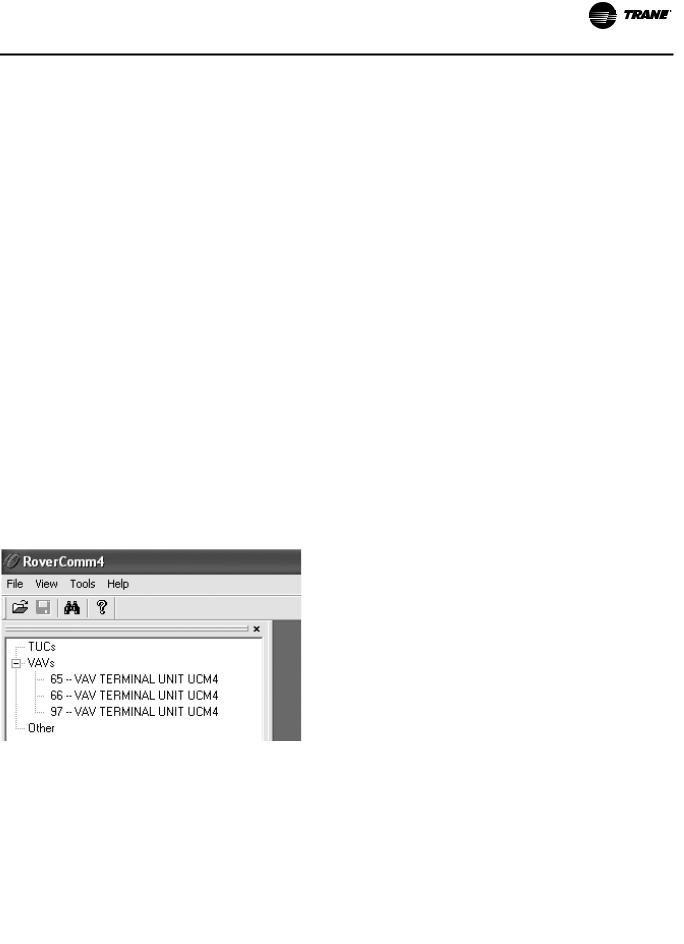
Note: When using Rover™ service tool to communicate to the UCM, you must add 64 to the DIP switch address. For example, a UCM with the DIP switch address set to 1 would be UCM Number 65 in Rover.
Figure 2. Rover screen/application
Table 6. |
DIP switch settings for UCM 4.2 |
|
|
|||||||
|
|
|
|
|
|
|
|
|
|
|
|
UCM |
|
|
|
|
|
Dip |
|
|
|
|
|
|
|
|
|
|
|
|
|
|
|
Unit # |
Address |
1 |
2 |
3 |
|
4 |
5 |
6 |
|
|
|
|
|
|
|
|
|
|
|
|
1 |
|
65 |
OFF |
ON |
ON |
|
ON |
ON |
ON |
|
|
|
|
|
|
|
|
|
|
|
|
2 |
|
66 |
ON |
OFF |
ON |
|
ON |
ON |
ON |
|
|
|
|
|
|
|
|
|
|
|
|
3 |
|
67 |
OFF |
OFF |
ON |
|
ON |
ON |
ON |
|
|
|
|
|
|
|
|
|
|
|
|
4 |
|
68 |
ON |
ON |
OFF |
|
ON |
ON |
ON |
|
|
|
|
|
|
|
|
|
|
|
|
5 |
|
69 |
OFF |
ON |
OFF |
|
ON |
ON |
ON |
|
|
|
|
|
|
|
|
|
|
|
|
6 |
|
70 |
ON |
OFF |
OFF |
|
ON |
ON |
ON |
|
|
|
|
|
|
|
|
|
|
|
|
7 |
|
71 |
OFF |
OFF |
OFF |
|
ON |
ON |
ON |
|
|
|
|
|
|
|
|
|
|
|
|
8 |
|
72 |
ON |
ON |
ON |
|
OFF |
ON |
ON |
|
|
|
|
|
|
|
|
|
|
|
|
Table 6. |
DIP switch settings for UCM 4.2 (continued) |
|||||||||
|
|
|
|
|
|
|
|
|
|
|
|
UCM |
|
|
|
|
|
Dip |
|
|
|
|
|
|
|
|
|
|
|
|
|
|
|
Unit # |
Address |
1 |
2 |
3 |
|
4 |
5 |
6 |
|
|
|
|
|
|
|
|
|
|
|
|
9 |
|
73 |
OFF |
ON |
ON |
|
OFF |
ON |
ON |
|
|
|
|
|
|
|
|
|
|
|
|
10 |
|
74 |
ON |
OFF |
ON |
|
OFF |
ON |
ON |
|
|
|
|
|
|
|
|
|
|
|
|
11 |
|
75 |
OFF |
OFF |
ON |
|
OFF |
ON |
ON |
|
|
|
|
|
|
|
|
|
|
|
|
12 |
|
76 |
ON |
ON |
OFF |
|
OFF |
ON |
ON |
|
|
|
|
|
|
|
|
|
|
|
|
13 |
|
77 |
OFF |
ON |
OFF |
|
OFF |
ON |
ON |
|
|
|
|
|
|
|
|
|
|
|
|
14 |
|
78 |
ON |
OFF |
OFF |
|
OFF |
ON |
ON |
|
|
|
|
|
|
|
|
|
|
|
|
15 |
|
79 |
OFF |
OFF |
OFF |
|
OFF |
ON |
ON |
|
|
|
|
|
|
|
|
|
|
|
|
16 |
|
80 |
ON |
ON |
ON |
|
ON |
OFF |
ON |
|
|
|
|
|
|
|
|
|
|
|
|
17 |
|
81 |
OFF |
ON |
ON |
|
ON |
OFF |
ON |
|
|
|
|
|
|
|
|
|
|
|
|
18 |
|
82 |
ON |
OFF |
ON |
|
ON |
OFF |
ON |
|
|
|
|
|
|
|
|
|
|
|
|
19 |
|
83 |
OFF |
OFF |
ON |
|
ON |
OFF |
ON |
|
|
|
|
|
|
|
|
|
|
|
|
20 |
|
84 |
ON |
ON |
OFF |
|
ON |
OFF |
ON |
|
|
|
|
|
|
|
|
|
|
|
|
21 |
|
85 |
OFF |
ON |
OFF |
|
ON |
OFF |
ON |
|
|
|
|
|
|
|
|
|
|
|
|
22 |
|
86 |
ON |
OFF |
OFF |
|
ON |
OFF |
ON |
|
|
|
|
|
|
|
|
|
|
|
|
23 |
|
87 |
OFF |
OFF |
OFF |
|
ON |
OFF |
ON |
|
|
|
|
|
|
|
|
|
|
|
|
24 |
|
88 |
ON |
ON |
ON |
|
OFF |
OFF |
ON |
|
|
|
|
|
|
|
|
|
|
|
|
25 |
|
89 |
OFF |
ON |
ON |
|
OFF |
OFF |
ON |
|
|
|
|
|
|
|
|
|
|
|
|
26 |
|
90 |
ON |
OFF |
ON |
|
OFF |
OFF |
ON |
|
|
|
|
|
|
|
|
|
|
|
|
27 |
|
91 |
OFF |
OFF |
ON |
|
OFF |
OFF |
ON |
|
|
|
|
|
|
|
|
|
|
|
|
28 |
|
92 |
ON |
ON |
OFF |
|
OFF |
OFF |
ON |
|
|
|
|
|
|
|
|
|
|
|
|
29 |
|
93 |
OFF |
ON |
OFF |
|
OFF |
OFF |
ON |
|
|
|
|
|
|
|
|
|
|
|
|
30 |
|
94 |
ON |
OFF |
OFF |
|
OFF |
OFF |
ON |
|
|
|
|
|
|
|
|
|
|
|
|
31 |
|
95 |
OFF |
OFF |
OFF |
|
OFF |
OFF |
ON |
|
|
|
|
|
|
|
|
|
|
|
|
32 |
|
96 |
ON |
ON |
ON |
|
ON |
ON |
OFF |
|
|
|
|
|
|
|
|
|
|
|
|
33 |
|
97 |
OFF |
ON |
ON |
|
ON |
ON |
OFF |
|
|
|
|
|
|
|
|
|
|
|
|
34 |
|
98 |
ON |
OFF |
ON |
|
ON |
ON |
OFF |
|
|
|
|
|
|
|
|
|
|
|
|
35 |
|
99 |
OFF |
OFF |
ON |
|
ON |
ON |
OFF |
|
|
|
|
|
|
|
|
|
|
|
|
36 |
|
100 |
ON |
ON |
OFF |
|
ON |
ON |
OFF |
|
|
|
|
|
|
|
|
|
|
|
|
37 |
|
101 |
OFF |
ON |
OFF |
|
ON |
ON |
OFF |
|
|
|
|
|
|
|
|
|
|
|
|
38 |
|
102 |
ON |
OFF |
OFF |
|
ON |
ON |
OFF |
|
|
|
|
|
|
|
|
|
|
|
|
39 |
|
103 |
OFF |
OFF |
OFF |
|
ON |
ON |
OFF |
|
|
|
|
|
|
|
|
|
|
|
|
40 |
|
104 |
ON |
ON |
ON |
|
OFF |
ON |
OFF |
|
|
|
|
|
|
|
|
|
|
|
|
41 |
|
105 |
OFF |
ON |
ON |
|
OFF |
ON |
OFF |
|
|
|
|
|
|
|
|
|
|
|
|
42 |
|
106 |
ON |
OFF |
ON |
|
OFF |
ON |
OFF |
|
|
|
|
|
|
|
|
|
|
|
|
43 |
|
107 |
OFF |
OFF |
ON |
|
OFF |
ON |
OFF |
|
|
|
|
|
|
|
|
|
|
|
|
44 |
|
108 |
ON |
ON |
OFF |
|
OFF |
ON |
OFF |
|
|
|
|
|
|
|
|
|
|
|
|
45 |
|
109 |
OFF |
ON |
OFF |
|
OFF |
ON |
OFF |
|
|
|
|
|
|
|
|
|
|
|
|
46 |
|
110 |
ON |
OFF |
OFF |
|
OFF |
ON |
OFF |
|
|
|
|
|
|
|
|
|
|
|
|
47 |
|
111 |
OFF |
OFF |
OFF |
|
OFF |
ON |
OFF |
|
|
|
|
|
|
|
|
|
|
|
|
48 |
|
112 |
ON |
ON |
ON |
|
ON |
OFF |
OFF |
|
|
|
|
|
|
|
|
|
|
|
|
49 |
|
113 |
OFF |
ON |
ON |
|
ON |
OFF |
OFF |
|
|
|
|
|
|
|
|
|
|
|
|
50 |
|
114 |
ON |
OFF |
ON |
|
ON |
OFF |
OFF |
|
|
|
|
|
|
|
|
|
|
|
|
51 |
|
115 |
OFF |
OFF |
ON |
|
ON |
OFF |
OFF |
|
|
|
|
|
|
|
|
|
|
|
|
52 |
|
116 |
ON |
ON |
OFF |
|
ON |
OFF |
OFF |
|
|
|
|
|
|
|
|
|
|
|
|
53 |
|
117 |
OFF |
ON |
OFF |
|
ON |
OFF |
OFF |
|
|
|
|
|
|
|
|
|
|
|
|
54 |
|
118 |
ON |
OFF |
OFF |
|
ON |
OFF |
OFF |
|
|
|
|
|
|
|
|
|
|
|
|
55 |
|
119 |
OFF |
OFF |
OFF |
|
ON |
OFF |
OFF |
|
|
|
|
|
|
|
|
|
|
|
|
56 |
|
120 |
ON |
ON |
ON |
|
OFF |
OFF |
OFF |
|
|
|
|
|
|
|
|
|
|
|
|
57 |
|
121 |
OFF |
ON |
ON |
|
OFF |
OFF |
OFF |
|
|
|
|
|
|
|
|
|
|
|
|
58 |
|
122 |
ON |
OFF |
ON |
|
OFF |
OFF |
OFF |
|
|
|
|
|
|
|
|
|
|
|
|
59 |
|
123 |
OFF |
OFF |
ON |
|
OFF |
OFF |
OFF |
|
|
|
|
|
|
|
|
|
|
|
|
VAV-SVX01D-EN |
13 |
UCM 4.2 Installation and Wiring
Table 6. |
DIP switch settings for UCM 4.2 (continued) |
|
|||||||||
|
|
|
|
|
|
|
|
|
|
|
|
|
UCM |
|
|
|
|
|
Dip |
|
|
|
|
|
|
|
|
|
|
|
|
|
|
|
|
|
Unit # |
Address |
1 |
2 |
3 |
|
4 |
5 |
6 |
|
|
|
|
|
|
|
|
|
|
|
|
|
|
60 |
|
124 |
ON |
ON |
OFF |
|
OFF |
OFF |
OFF |
|
|
|
|
|
|
|
|
|
|
|
|
|
|
61 |
|
125 |
OFF |
ON |
OFF |
|
OFF |
OFF |
OFF |
|
|
|
|
|
|
|
|
|
|
|
|
|
|
62 |
|
126 |
ON |
OFF |
OFF |
|
OFF |
OFF |
OFF |
The following figures show wiring diagrams for typical |
|
|
|
|
|
|
|
|
|
|
|
|
|
63 |
|
127 |
OFF |
OFF |
OFF |
|
OFF |
OFF |
OFF |
||
|
|
applications of UCM 4.2 |
|||||||||
|
|
|
|
|
|
|
|
|
|
|
|
|
|
|
|
|
|
|
|
|
|
|
|
|
|
|
|
|
|
|
|
|
|
|
. |
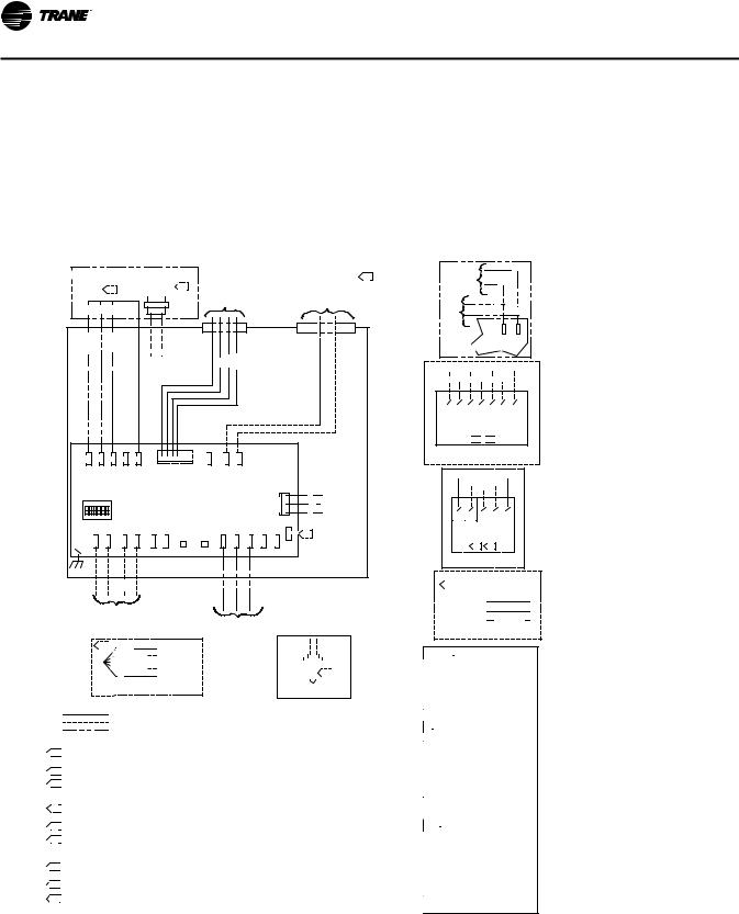
Figure 3. Wiring diagram for single duct units with factory installed electric reheat
HEATER STAGE |
|
|
|
|
|
|
|
|
|
|
|
|
24VAC 60HZ |
8. |
|||
|
|
|
|
|
|
|
|
|
|
|
|
NEC CLASS-2 |
|||||
CONTACTOR(S) |
|
|
|
|
|
DAMPER |
|
|
|
|
|||||||
|
|
OPTIONAL |
10. |
|
|
|
|
|
|||||||||
|
|
9. |
|
|
ACTUATOR |
|
|
|
|
CONTROL CIRCUIT |
|
||||||
|
|
|
|
|
|
|
|
|
|
|
|||||||
|
|
|
|
TRANSFORMER |
|
|
|
|
LOAD= 12VA |
|
|||||||
|
|
|
|
|
|
|
|
|
WIRING |
|
|
|
|
|
|||
|
|
|
|
|
|
|
|
|
|
|
|
|
(WITHOUT HEAT) |
|
|||
3RD |
2ND |
1ST |
|
|
|
|
|
|
|
|
|
|
|
|
|
||
|
|
|
|
|
|
|
|
|
|
|
|
|
|
|
|||
3RDSTG. |
2NDSTG. |
1STSTG. |
|
HOT |
Y |
BL |
|
|
HOT OPEN |
CLOSE |
|
|
|
|
|
|
|
R |
V |
O |
|
BR |
TB1-2 |
TB1-1 |
|
HOT |
|
|
|
|
|
|
|
||
|
|
|
|
|
J1 |
|
|
1 |
TB1-2 |
TB1-1 |
|
|
|
|
|
|
|
J11 |
J10 |
J9 |
J7 |
J8 |
|
|
ACT |
TB41- |
|
|
|
|
|
PRESSURE |
|
||
|
|
|
|
|
|
|
BIP |
GND 24V |
|
|
|
|
|
||||
|
|
|
|
|
|
|
|
|
|
|
|
TRANSDUCER |
|
||||
|
|
|
|
|
|
|
|
|
|
|
|
|
|
|
|
|
|
ADDRESS |
|
|
|
D.D.C.\U.C.M. |
|
|
|
|
J3 |
|
R |
|
|
||||
SWITCH |
|
|
|
CONTROL BOARD |
|
|
|
|
|
|
+ |
|
|||||
|
|
|
|
|
|
|
PRESS |
|
BK |
|
|||||||
|
|
|
|
|
|
|
|
|
|
|
|
|
|
VOUT |
|
||
|
|
|
|
|
|
|
|
|
|
|
|
|
|
|
|
||
|
|
|
|
|
|
|
|
|
|
|
|
|
|
G |
- |
|
|
|
|
|
|
|
|
|
|
|
|
|
|
|
|
|
|
|
|
|
|
|
|
|
|
|
|
|
|
|
|
|
1 |
|
|
|
|
|
+ |
- |
+ |
- |
+ |
- |
|
|
ZONE |
GND |
SET |
A/CO2 |
GND |
|
|
|
|
|
|
|
|
|
|
|
|
|
S |
7. |
|
|
|||||
TB2-1 |
TB2-2 |
|
TB2-3 |
TB2-4 |
TB2-5 |
TB2-6 |
YEL |
GRN |
TB3-1 |
TB3-2 |
TB3-3 |
TB3-5 |
TB3-6 |
|
|
||
|
|
|
|
|
|||||||||||||
|
|
|
|
|
|
|
|||||||||||
IN |
IN |
|
OUT |
OUT |
|
|
|
|
|
|
|
|
|
|
|
D.D.C.\U.C.M. |
|
CONTROL BOX
SHIELDED TWISTED PAIR
COMMUNICATIONS WIRING
OPTIONAL FACTORY INSTALLED
WIRELESS
5. |
R (HOT) |
(TB1-1) 24VAC |
TB3-5 |
|
|
|
|
|
|
|
|
TB3-6 |
|
|
O (COMMON) |
(TB4-1) BIP |
|
|
|
|
|
|
|
|
|
|
|
|
|
|
|
|
|
|
|
|
|
|
|
||
|
GR (NC CONTACT) |
(TB1-1) 24VAC |
|
|
|
|
|
|
|
|
|
|
|
|
BK (RETURN) |
(TB1-2) GND |
|
|
|
|
|
|
6. |
|
|||
|
Y |
NOT CONNECTED |
|
|
|
|
|
|
|
||||
|
|
|
|
|
|
|
|
|
|
|
|
|
|
|
OPTIONAL FIELD INSTALLED |
|
OPTIONAL |
||||||||||
|
OCCUPANCY SENSOR |
AUX TEMP SENSOR |
|||||||||||
|
|
|
|||||||||||
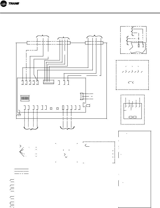
NOTE:
1.FACTORY WIRING FIELD WIRING
OPTIONAL OR ALTERNATE WIRING
2.1/4" QUICK CONNECT REQUIRED FOR ALL FIELD CONNECTIONS.

 3.
3.
 ZONE SENSOR TERMINALS 1 (-) AND 2 (+) REQUIRE SHIELDED TWISTED PAIR
WIRING FOR COMMUNICATIONS JACK EQUIPPED ZONE SENSOR OPTION.

 4.
4.
 NO ADDITIONAL WIRING REQUIRED FOR NIGHT SETBACK OVERRIDE (ON/CANCEL).

 5.
5.
 THE OPTIONAL BINARY INPUT CONNECTS BETWEEN TB4-1 (BIP) AND 24VAC (HOT) FROM TRANSFORMER. THE BINARY INPUT CAN BE RECONFIGURED AS AN OCCUPANCY INPUT VIA THE COMMUNICATIONS INTERFACE.
6.
 AS SHIPPED, THE AUX INPUT IS CONFIGURED AS AN AUX TEMP INPUT. THE AUX INPUT CAN BE RECONFIGURED AS A CO2 SENSOR INPUT VIA THE COMMUNICATIONS INTERFACE.

 7.
7.
 S TERMINAL NOT TO BE USED WITH VARITRANE.

 8.
8.
 IF UNIT MOUNTED TRANFORMER IS NOT PROVIDED, POLARITY FROM UNIT TO UNIT MUST BE MAINTAINED TO PREVENT PERMANENT DAMAGE TO CONTROL BOARD. IF ONE LEG OF 24VAC SUPPLY IS GROUNDED, THEN GROUND LEG MUST BE CONNECTED TO TB1-2.

 9.
9.
 CONTACTORS ARE 24 VAC: 12VA MAX/COIL (MERCURY CONTACTORS). 10VA MAX/COIL (MAGNETIC CONTACTORS)
 10.
10.
 OPTIONAL FUSE, DISCONNECT SWITCH & TRANSFORMER LOCATED IN HEATER.
11.
 ZONE SENSOR TERMINALS 6 AND 7 REQUIRE SHIELDED TWISTED PAIR WIRING FOR OPTIONAL USE OF COMMUNICATIONS JACK.
OPTIONAL |
|
BL |
|
|
|
FACTORY |
Y |
|
INSTALLED |
|
|
WIRELESS |
|
|
|
Y |
|
24VAC |
|
BL |
|
TB1-2 |
TB1-1 |
GND 24V |
UCM or EI Board |
TB1-1
 TB2-6
TB2-6
 TB3-3
TB3-3
 TB3-1
TB3-1

 TB1-2
TB1-2

 TB2-5
TB2-5

 TB3-2
TB3-2
11 |
10 |
7 |
6 |
3 |
2 |
1 |
DIGITAL DISPLAY ZONE SENSOR
W/ COMM. JACK
REMOTE MTD.

 4.
4.

 11.
11.

OPTIONAL FIELD INSTALLED
DIGITAL DISPLAY ZONE SENSOR
TB2-6 |
|
|
TB3-1 |
|
|
TB2-5 |
TB3-2 |
||
|
|
TB3-3 |
|
|
2(+) |
1(-) |
3 |
2 |
1 |
|
ZONE SENSOR |
|
||
|
W/ COMM. JACK |
|
||
|
REMOTE MTD. |
|
||
|
|
3. |
4. |
|
OPTIONAL FIELD
INSTALLED ZONE SENSOR
|
|
|
WALL MOUNTED |
DUCT MOUNTED |
|
|
6. |
|
|
||||
|
|
|
|
|
(TB1-1) 24V |
|
|
CO2 |
24V |
+ |
|
||
|
GND |
|
(TB3-6) GND |
|||
SENSOR |
0 |
|||||
|
||||||
|
|
|
OUT |
V |
(TB3-5) A/CO2 |
|
OPTIONAL FIELD INSTALLED
CO2 SENSOR
 WARNING
HAZARDOUS VOLTAGE!
DISCONNECT ALL ELECTRIC POWER INCLUDING REMOTE DISCONNECTS AND FOLLOW LOCK OUT AND TAG PROCEDURES BEFORE SERVICING. INSURE THAT ALL MOTOR CAPACITORS HAVE DISCHARGED STORED VOLTAGE. UNITS WITH VARIABLE SPEED DRIVE, REFER TO DRIVE INSTRUCTIONS FOR CAPACITOR DISCHARGE.
FAILURE TO DO THE ABOVE COULD RESULT IN DEATH OR SERIOUS INJURY.
 AVERTISSEMENT
TENSION DANGEREUSE!
COUPER TOUTES LES TENSIONS ET OUVRIR LES SECTIONNEURS À DISTANCE, PUIS SUIVRE LES PROCÉDURES DE
VERROUILLAGE ET DES ÉTIQUETTES AVANT
TOUTE INTERVENTION. VÉRIFIER QUE TOUS LES CONDENSATEURS DES MOTEURS SONT
DÉCHARGÉS. DANS LE CAS D'UNITÉS COMPORTANT DES ENTRAÎNEMENTS À VITESSE VARIABLE, SE REPORTER AUX
INSTRUCTIONS DE L'ENTRAÎNEMENT POUR DÉCHARGER LES CONDENSATEURS.
NE PAS RESPECTER CES MESURES DE PRÉCAUTION PEUT ENTRAÎNER DES BLESSURES GRAVES POUVANT ÊTRE MORTELLES.
 ADVERTENCIA
iVOLTAJE PELIGROSO!
DESCONECTE TODA LA ENERGà A ELÉCTRICA, INCLUSO LAS DESCONEXIONES REMOTAS Y SIGA LOS PROCEDIMIENTOS DE CIERRE Y ETIQUETADO ANTES DE PROCEDER AL SERVICIO. ASEGÚRESE DE QUE TODOS
LOS CAPACITORES DEL MOTOR HAYAN DESCARGADO EL VOLTAJE ALMACENADO. PARA LAS UNIDADES CON TRANSMISIÓN DE VELOCIDAD VARIABLE, CONSULTE LAS INSTRUCCIONES PARA LA DESCARGA DEL CONDENSADOR.
EL NO REALIZAR LO ANTERIORMENTE
INDICADO, PODRÃ A OCASIONAR LA MUERTE O SERIAS LESIONES PERSONALES.
14 |
VAV-SVX01D-EN |

UCM 4.2 Installation and Wiring
Figure 4. Wiring diagram for fan-powered units with field installed reheat
VAV-SVX01D-EN |
15 |
UCM 4.2 Installation and Wiring
Figure 5. Wiring diagram for fan-powered units with factory installed electric reheat
|
|
|
|
|
HEATER |
|
DAMPER |
|
|
|
|
|
||||
|
|
|
|
TERMINAL |
|
|
|
FAN CONTROL |
||||||||
|
|
|
|
|
ACTUATOR |
|
|
|||||||||
|
|
|
|
BOX WIRING |
|
|
|
|||||||||
|
|
|
|
|
|
|
|
BOX WIRING |
||||||||
|
|
|
|
|
WIRING |
|
|
|
||||||||
|
|
|
|
|
|
|
|
|
|
|
|
|
||||
|
|
2ND STG HEAT |
|
|
|
|
|
|
|
|
|
|
|
|
||
|
V |
1ST STG HEAT |
BR-HOT |
|
HOT |
HOT OPEN |
CLOSE |
|
|
|
|
|
|
|||
|
|
O |
|
|
|
|
|
|
|
|
|
|
|
|
|
|
|
|
|
|
|
|
|
|
|
|
|
|
|
|
R-FAN |
|
|
|
|
|
|
|
|
|
|
|
|
|
|
|
|
|
BR |
|
|
|
|
|
|
|
|
|
|
|
|
|
|
|
|
|
Y |
|
|
|
|
|
|
|
|
|
|
|
|
|
|
24 VAC |
|
BL |
|
|
|
|
|
J1 |
|
|
1 |
TB1-2 |
TB1-1 |
|
|
|
|
|
|
J11 |
J10 |
J9 |
J7 |
J8 |
|
ACT |
TB41- |
|
|
|
|
|
|
|||
|
|
|
|
|
|
BIP |
GND |
24V |
|
|
|
|
PRESSURE |
|||
|
|
|
|
|
|
|
|
|
|
|
|
|||||
ADDRESS |
|
|
|
D.D.C.\U.C.M. |
|
|
|
|
|
|
|
TRANSDUCER |
||||
|
|
|
|
|
|
|
|
J3 |
R |
+ |
||||||
SWITCH |
|
|
CONTROL BOARD |
|
|
|
|
|
|
|||||||
|
|
|
|
|
|
|
PRESS |
BK |
||||||||
|
|
|
|
|
|
|
|
|
|
|
|
|
|
VOUT |
||
|
|
|
|
|
|
|
|
|
|
|
|
|
|
G |
||
|
|
|
|
|
|
|
|
|
|
|
|
|
|
|
|
- |
|
|
|
|
|
|
|
|
|
|
|
|
|
|
1 |
|
|
|
+ |
- |
+ |
- |
+ |
- |
|
|
ZONE |
GND SET |
A/CO2 |
|
GND |
|
|
|
|
TB2-1 |
TB2-2 |
TB2-3 |
TB2-4 |
TB2-5 |
TB2-6 |
YEL |
GRN |
TB3-1 |
TB3-2 |
TB3-3 |
TB3-5 |
TB3-6 |
S |
7. |
|
|
|
|
|
|||||||||||||
|
|
|
|
|
|
|||||||||||
|
IN |
IN |
OUT |
OUT |
|
|
|
|
|
|
|
|
|
|
D.D.C.\U.C.M. |
|
|
|
|
|
|
|
|
|
|
|
|
CONTROL BOX |
|||||
|
|
|
|
|
|
|
|
|
|
|
|
|
|
|
||
BL
OPTIONAL
FACTORY
INSTALLED 
 Y
Y
WIRELESS
|
Y |
24VAC |
BL |
TB1-2 |
TB1-1 |
|
GND 24V |
UCM or EI Board |
|
TB1-1 |
TB2-6 TB3-3 |
|
TB3-1 |
|||||||||||
|
|
TB1-2 |
|
TB2-5 |
|
TB3-2 |
|
|||||||
|
|
|
|
|
||||||||||
|
|
|
|
|
||||||||||
|
|
|
|
|
|
|
|
|
|
|
|
|
|
|
|
|
|
|
|
|
|
|
|
|
|
|
|
|
|
|
|
|
|
|
|
|
|
|
|
|
|
|
|
|
|
|
|
|
|
|
|
|
|
|
|
|
|
|
|
11 |
10 |
7 |
6 |
|
3 |
|
2 |
1 |
||||||
DIGITAL DISPLAY ZONE SENSOR |
||||||||||||||
|
|
|
|
W/ COMM. JACK |
|
|
|
|||||||
|
|
|
|
REMOTE MTD. |
|
|
|
|||||||
|
|
|
|
|
|
4. |
|
|
|
|
|
|
|
|
|
|
|
|
|
|
|
|
|
6. |
|
|
|
|
|
|
|
|
|
|
|
|
|
|
|
|
|
|
|
|
OPTIONAL FIELD INSTALLED DIGITAL DISPLAY ZONE SENSOR
TB2-6 |
|
|
TB3-1 |
|
|
TB2-5 |
TB3-2 |
||
|
|
TB3-3 |
|
|
2(+) |
1(-) |
3 |
2 |
1 |
|
ZONE SENSOR |
|
||
|
W/ COMM. JACK |
|
||
|
REMOTE MTD. |
|
||
|
|
3. |
4. |
|
OPTIONAL FIELD
INSTALLED ZONE SENSOR
SHIELDED |
OPTIONAL FACTORY INSTALLED |
|
WIRELESS |
||
TWISTED PAIR |
||
|
||
COMMUNICATIONS |
|
|
WIRING |
|
|
|
|
|
|
|
|
|
|
|
|
|
|
|
|
|
|
|
|
|
|
|
|
|
|
|
|
|
|
|
|
|
|
|
|
|
|
|
|
|
|
|
|
|
|
|
|
|
|
|
|
|
|
|
|
|
|
|
|
|
|
|
|
|
|
|
|
|
|
|
|
|
|
|
|
|
WALL MOUNTED |
DUCT MOUNTED |
|
|
|
|
|
|
|
|
|
|
|
|
|
|
||||||||||
|
5. |
|
R (HOT) |
|
|
|
|
|
(TB1-1) 24VAC |
|
|
TB3-5 |
|
|
|
|
|
|
|
|
|
|
|
|
|
|
TB3-6 |
|
|
6. |
|
|
|
|
|
|
|
|
|
|
|
|
|
|
|
|
|
|
|
||||||||||||||||||||||||||||||||||||||||||||||||||||
|
|
|
|
|
O |
|
|
(COMMON) |
|
|
|
|
|
|
|
|
|
|
|
|
|
|
|
|
|
|
|
|
|
|
|
|
|
|
|
|
|
|
|
|
|
|
|
|
|
|
|
|
|
|
|
(TB1-1) 24V |
|||||||||||||||||||||||||||||||||||||||||||||||||
|
|
|
|
|
|
|
|
|
|
|
|
|
|
|
|
|
(TB4-1) BIP |
|
|
|
|
|
|
|
|
|
|
|
|
|
|
|
|
|
|
|
|
|
|
|
|
|
|
|
|
|
|
|
|
|
|
|
|
|
|
|
|
|
|
|
24V |
+ |
|
|
|
|
|
|
|
|
|
|
|
|
|
|
|
||||||||||||||||||||||||
|
|
|
|
|
GR (NC CONTACT) |
(TB1-1) 24VAC |
|
|
|
|
|
|
|
|
|
|
|
|
|
|
|
|
|
|
|
|
|
|
|
|
|
|
|
|
|
|
|
|
|
|
CO2 |
|
|
|
|
|
|
|
|
(TB3-6) GND |
|||||||||||||||||||||||||||||||||||||||||||||||||||
|
|
|
|
|
BK (RETURN) |
|
|
|
|
|
|
|
|
|
|
|
|
|
|
|
|
|
|
|
|
|
|
|
|
|
|
|
|
|
|
|
|
|
|
GND |
|
|
|
|
|
|
|
||||||||||||||||||||||||||||||||||||||||||||||||||||||
|
|
|
|
|
|
Y |
|
|
|
|
|
|
|
|
(TB1-2) GND |
|
|
|
|
|
|
|
|
6. |
|
|
|
|
|
|
|
|
|
|
|
|
|
|
|
|
|
|
|
|
SENSOR |
0 |
|
|
|
|
|
|
|
|
|
|
|
|
|
|
|
||||||||||||||||||||||||||||||||||||||||
|
|
|
|
|
|
|
|
|
|
|
|
|
|
NOT CONNECTED |
|
|
|
|
|
|
|
|
|
|
|
|
|
|
|
|
|
|
|
|
|
|
|
|
|
|
|
|
|
|
|
|
|
|
|
|
|
|
|
|
|
|
OUT |
|
|
|
V |
|
|
(TB3-5) A/CO2 |
|||||||||||||||||||||||||||||||||||||
|
|
|
|
|
|
|
|
|
|
|
|
|
|
|
|
|
|
|
|
|
|
|
|
|
|
|
|
|
|
|
|
|
|
|
|
|
|
|
|
|
|
|
|
OPTIONAL |
|
|
|
|
|
|
|
|
|
|
|
|
|
|
|
|
|
|
|
|
|
|
|
|
|
|
|
|
|
|
|
|
|
|
|
|
|
|
|||||||||||||||||||
|
|
|
|
OPTIONAL FIELD INSTALLED |
|
|
|
|
|
|
|
|
|
|
|
|
|
|
|
|
|
OPTIONAL FIELD INSTALLED |
|||||||||||||||||||||||||||||||||||||||||||||||||||||||||||||||||||||||||||||||
|
|
|
|
|
|
OCCUPANCY SENSOR |
|
|
|
|
|
|
AUX TEMP SENSOR |
|
|
|
|
|
|
|
|
|
|
|
|
|
|
CO2 SENSOR |
|||||||||||||||||||||||||||||||||||||||||||||||||||||||||||||||||||||||||
|
|
|
|
|
|
|
|
|
|
|
|
|
|
|
|
|
|
|
|
|
|
|
|
|
|
|
|
|
|
|
|
|
|
|
|
|
|
|
|
|
|
|
|
|
|
|
|
|
|
|
|
|
|
|
|
|
|
|
|
|
|
|
|
|
|
|
|
|
|
|
|
|
|
|
|
|
|
||||||||||||||||||||||||
|
|
|
|
|
|
|
|
|
|
|
|
|
|
|
|
|
|
|
|
|
|
|
|
|
|
|
|
|
|
|
|
|
|
|
|
|
|
|
|
|
|
|
|
|
|
|
|
|
|
|
|
|
|
|
|
|
|
|
|
|
|
|
|
|
|
|
|
|
|
|
|
|
|
|
|
|
|
|
|
|
|
|
|
|
|
|
|
|
|
|
|
|
|
|
|
|
|
|
|
|
|
NOTE:
1.FACTORY WIRING FIELD WIRING
OPTIONAL OR ALTERNATE WIRING
2.1/4" QUICK CONNECT REQUIRED FOR ALL FIELD CONNECTIONS.

 3.
3.
 ZONE SENSOR TERMINALS 1 (-) AND 2 (+) REQUIRE SHIELDED TWISTED PAIR WIRING FOR COMMUNICATIONS JACK EQUIPPED ZONE SENSOR OPTION.

 4.
4.
 NO ADDITIONAL WIRING REQUIRED FOR NIGHT SETBACK OVERRIDE (ON/CANCEL).

 5.
5.
 THE OPTIONAL BINARY INPUT CONNECTS BETWEEN TB4-1 (BIP) AND 24VAC (HOT) FROM TRANSFORMER. THE BINARY INPUT CAN BE RECONFIGURED AS AN OCCUPANCY INPUT VIA THE COMMUNICATIONS INTERFACE.

 6.
6.
 AS SHIPPED, THE AUX INPUT IS CONFIGURED AS AN AUX TEMP INPUT. THE AUX INPUT CAN BE RECONFIGURED AS A CO2 SENSOR INPUT VIA THE COMMUNICATIONS INTERFACE.
7.
 S TERMINAL NOT TO BE USED WITH VARITRANE.

 8.
8.
 ZONE SENSOR TERMINALS 6 AND 7 REQUIRE SHIELDED TWISTED PAIR WIRING FOR COMMUNICATIONS JACK EQUIPPED ZONE SENSOR OPTION.

 WARNING
HAZARDOUS VOLTAGE!
DISCONNECT ALL ELECTRIC POWER INCLUDING REMOTE DISCONNECTS AND FOLLOW LOCK OUT AND TAG PROCEDURES BEFORE SERVICING. INSURE THAT ALL MOTOR CAPACITORS HAVE DISCHARGED STORED VOLTAGE. UNITS WITH VARIABLE SPEED DRIVE, REFER TO DRIVE INSTRUCTIONS FOR CAPACITOR DISCHARGE.
FAILURE TO DO THE ABOVE COULD RESULT IN DEATH OR SERIOUS INJURY.

 AVERTISSEMENT
TENSION DANGEREUSE!
COUPER TOUTES LES TENSIONS ET OUVRIR LES SECTIONNEURS À DISTANCE, PUIS SUIVRE LES PROCÉDURES DE
VERROUILLAGE ET DES ÉTIQUETTES AVANT
TOUTE INTERVENTION. VÉRIFIER QUE TOUS
LES CONDENSATEURS DES MOTEURS SONT
DÉCHARGÉS. DANS LE CAS D'UNITÉS COMPORTANT DES ENTRAÎNEMENTS À VITESSE VARIABLE, SE REPORTER AUX INSTRUCTIONS DE L'ENTRAÎNEMENT POUR DÉCHARGER LES CONDENSATEURS.
NE PAS RESPECTER CES MESURES DE PRÉCAUTION PEUT ENTRAÎNER DES BLESSURES GRAVES POUVANT ÊTRE MORTELLES.

 ADVERTENCIA
iVOLTAJE PELIGROSO!
DESCONECTE TODA LA ENERGà A ELÉCTRICA, INCLUSO LAS DESCONEXIONES REMOTAS Y
SIGA LOS PROCEDIMIENTOS DE CIERRE Y ETIQUETADO ANTES DE PROCEDER AL SERVICIO. ASEGÚRESE DE QUE TODOS LOS CAPACITORES DEL MOTOR HAYAN DESCARGADO EL VOLTAJE ALMACENADO. PARA LAS UNIDADES CON TRANSMISIÓN DE VELOCIDAD VARIABLE, CONSULTE LAS
INSTRUCCIONES PARA LA DESCARGA DEL CONDENSADOR.
EL NO REALIZAR LO ANTERIORMENTE INDICADO, PODRÃ A OCASIONAR LA MUERTE O SERIAS LESIONES PERSONALES.
16 |
VAV-SVX01D-EN |
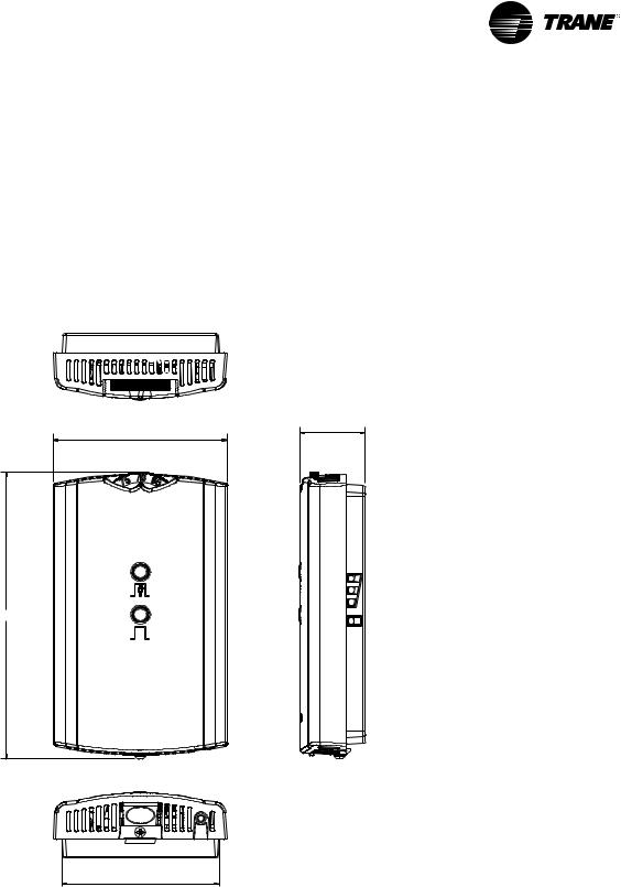
Wireless Zone Sensor
Overview
TheTrane Wireless Zone Sensor set includes a sensor and a receiver that work together to provide the same functions as the equivalentTrane wired sensor (#41901090), such as the standard 10 k temperature input (with the exception of the communication jack). No further software or hardware is necessary for site evaluation, installation, or maintenance.
The sensor transmits the zone temperature, all zone temperature setpoint functions, timed override Occupied
Figure 6. Outside dimensions for sensor
2.90 in (7.35 cm)
4.78 in (12.14 cm)
2.62 in (6.65 cm)
(On) and timed override Unoccupied (Cancel) information to the receiver.The receiver electrically reproduces the zone temperature resistance, all zone temperature setpoint function resistances, and timed override On and timed override Cancel information as sent by the sensor.
Dimensional Diagrams
See Figure 6, p. 17 and Figure 7, p. 18 for dimensions of the Wireless Zone Sensor set.The dimensions are the same for both the sensor and the receiver.
1.08 in (2.75 cm)
Note: The dimensions are the same for both the sensor and the receiver.
VAV-SVX01D-EN |
17 |
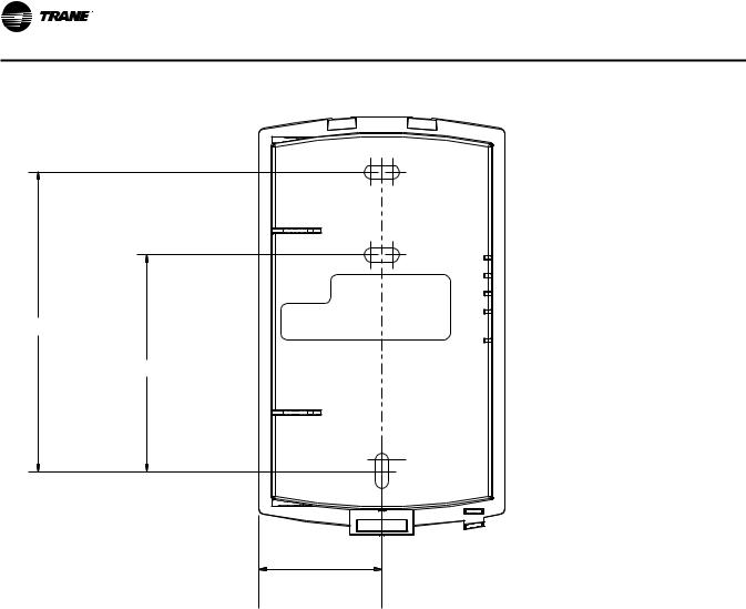
Wireless Zone Sensor
Figure 7. Mounting hole dimensions for sensor
3.27 in (8.30 cm)
2.36 in (6.00 cm)
1.34 in (3.41 cm) |
Note: The dimensions are the same for both the sensor and the receiver.
Setting the Address, Mounting,
Wiring, and Associating the
Receiver and Sensor
The following procedure list shows the recommended order for installation:
•Choosing a location for mounting the sensor
•Setting the rotary address switches on the receiver and on the sensor
•Replacing and securing the receiver cover
•Powering the sensor and associating the sensor to the receiver
•Applying power to the receiver
•Testing signal and battery strength
•Disassociation
Choosing a Location for Mounting the Sensor
Placement of the receiver and the sensor set is critical to proper operation. In most installations, distance is not the limiting factor for proper radio signal quality. It is more greatly affected by walls, barriers, and general clutter. For best radio transmission range and reliability, wherever possible, mount the receiver and sensor in line of sight.Try to minimize the number of barriers between the pair of devices. In general, sheetrock walls and ceiling tiles offer little restriction to the propagation of the radio signal throughout the building; concrete or metal barriers offer the most restriction.The transmission range for the sensor is as follows:
•Open range: 2,500 ft (762 m) (packet error rate = 2%)
•Usable range: 200 ft (61 m)
•Typical range: 75 ft (23 m)
18 |
VAV-SVX01D-EN |

Wireless Zone Sensor
Ambient considerations
Avoid locations that are outside the operating temperature and humidity range (see Table 14, p. 48).
•Avoid placing the sensor inside metal enclosures
•Avoid radio transmissions through thick, solid concrete walls
Location Considerations for the Sensor
When selecting a location for the sensor, consider both thermal and radio transmission characteristics of the location.
Thermal considerations
•Avoid areas of direct sunlight
•Avoid areas in the direct air stream of air diffusers
•Avoid exterior walls and other walls that have a temperature differential between their two sides
•Avoid areas close to sources of heat such as sunlight, appliances, or other equipment
•Avoid drafty areas
•Avoid dead spots behind doors, projection screens, or corners
Radio transmission considerations
•Avoid metal barriers between the sensor and receiver, such as plastered walls with metal lathe as they will decrease radio signal quality.
Setting the Rotary Address Switches on the Receiver and the Sensor
Note: To expedite the installation and association process, set the addresses before applying power to the receiver.
The process of establishing communication between the receiver and sensor is referred to as association.The receiver and the sensor must have their rotary switches set to the same address in order to enable communication between the two devices (see Figure 8, p. 19). Important limitations are as follows:
•Only one associated receiver/sensor set can communicate within the reception range of the wireless system.
•It is not possible to associate more than one sensor to a receiver, nor is it possible to associate more than one receiver to a sensor.
Figure 8. Setting the rotary address switches on the receiver and the sensor
Do not remove the insulation strip yet.
WIRELESS |
! |
INSTALL |
|
LED4 |
LED1 |
|
|
|
|
|
|
|
S4 |
|
|
|
|
|
|
|
|
|
|
|
||
|
|
|
|
|
|
|
|
|
||
|
|
|
|
|
|
|
|
|
|
|
LED2 |
|
|
|
|
|
|
|
|
|
|
LED3 |
|
|
|
|
|
|
|
|
|
|
SIGNAL |
S1 |
S2 |
S3 |
|
|
|
|
|
|
|
|
|
|
|
|
|
|||||
LED5 |
|
ADDRESS |
|
|
|
|
|
|
|
|
POWER |
|
|
C33 |
C34 |
|
|
||||
|
|
|
J1 |
|
|
|||||
|
|
|
|
|
|
|||||
|
|
|
HEATING SET |
|
|
|
|
|
|
|
|
S5 |
|
FAN/SYSTEM |
|
|
|
|
C35 |
|
|
S5 |
|
SETPOINT |
|
|
|
|
|
|
||
|
|
ZONE |
|
|
|
|
R77 |
|
|
|
|
|
GND |
|
|
|
|
|
|
||
24VAC/DC GND COMM + COMM -
Setting the Receiver Address
1.Using a small screwdriver, set the three rotary address switches (locations S1, S2, S3) on the receiver (Figure 8, p. 19) to an address between 001 and 999.
Note: Do not use 000 as an address for installation. If you set the receiver address to 000, it will:
–Return the receiver outputs to their factory defaults indefinitely (zone temperature and setpoint outputs: 72.5°F [22.5°C])
–Remove all association knowledge
B1 +
|
|
|
Pb |
|
|
|
Pb-FREE |
||
LED1 |
|
|
|
|
LED2 |
|
|
|
|
LED3 |
|
|
|
|
SIGNAL |
S1 |
S2 |
S3 |
|
LED4 |
||||
LED5 |
ADDRESS |
|||
BATTERY |
|
|
STATUS |
|
STATUS |
|
|
|
|
S4
WIRELESS
INSTALL
–Make the receiver unable to associate with a sensor
•Read the switches from left to right in the order in which they are numbered (S1, S2, S3).
•Zero is at the 9 o'clock position.
2.Make a notation of the address and location of the receiver.
VAV-SVX01D-EN |
19 |

Wireless Zone Sensor
Setting the Sensor Address
1.Using a small screwdriver, set the three rotary address switches (locations S1, S2, S3) on the sensor (Figure 8, p. 19) to the same address used for the receiver it is to be associated with.
2.Make a notation of the address and location where this sensor is to be mounted.
Note: Do not use 000 as an address for installation. If you set the address to 000, it will:
–Remove all association knowledge
–Revert to a low-power hibernation mode.
–Send a disassociation request to the receiver. If the sensor and receiver are associated and communicating at the time the sensor is set to 000 and theTest button is pressed, the receiver will also become unassociated and will be available for re-association.
•Read the switches from left to right in the order in which they are numbered (S1, S2, S3).
•Zero is at the 9 o'clock position.
3.Make a notation of the address and location of the sensor.
Factory Wiring of the Receiver to the VAV UCM
The required power for the receiver is 24 VAC or 24 Vdc and is less than 1 VA.The receiver is designed to be powered by the VAV UCM controller.
Note: A dedicated transformer is not necessary or advised.
20 |
VAV-SVX01D-EN |
Wireless Zone Sensor
Figure 9. Factory wiring of the receiver to the VAV UCM
W (HOT) |
|
|
24VAC 60HZ |
8. |
PROP. |
|
NEC CLASS-2 |
||
TO J8 |
WATER |
DAMPER |
|
|
BK (CLOSE) |
CONTROL CIRCUIT |
|
||
TO J9 |
VALVE |
ACTUATOR |
|
|
R (OPEN) |
24VAC |
LOAD= 12VA |
|
|
TO J10 |
12VA MAX |
WIRING |
|
|
|
|
(WITHOUT HEAT) |
|
|
OPTIONAL FIELD INSTALLED |
|
|
||
|
|
|
||
PROPORTIONAL WATER VALVE |
|
|
|
|
|
|
|
|
|
|
|
|
HOT |
HOT |
OPEN |
CLOSE |
|
|
|
|
|
|
|
|
|
|
|
J1 |
|
|
1 |
|
TB1-2 |
TB1-1 |
|
|
|
|
|
|
J11 |
J10 |
J9 |
J7 |
J8 |
|
|
ACT |
TB41- |
|
|
|
|
|
|
PRESSURE |
||
|
|
|
|
|
|
|
BIP |
|
GND |
24V |
|
|
|
|
|||
|
|
|
|
|
|
|
|
|
|
|
|
|
TRANSDUCER |
||||
|
|
|
|
|
|
|
|
|
|
|
|
|
|
|
|
|
|
ADDRESS |
|
|
|
D.D.C.\U.C.M. |
|
|
|
|
|
J3 |
|
R |
|
||||
SWITCH |
|
|
|
CONTROL BOARD |
|
|
|
|
|
|
|
+ |
|||||
|
|
|
|
|
|
|
|
PRESS |
|
BK |
|||||||
|
|
|
|
|
|
|
|
|
|
|
|
|
|
|
VOUT |
||
|
|
|
|
|
|
|
|
|
|
|
|
|
|
|
G |
||
|
|
|
|
|
|
|
|
|
|
|
|
|
|
|
|
|
- |
|
|
|
|
|
|
|
|
|
|
|
|
|
|
1 |
|
|
|
|
+ |
- |
+ |
- |
+ |
|
- |
|
ZONE |
GND |
SET |
A/CO2 |
GND |
|
|
|
|
|
TB2-1 |
TB2-2 |
TB2-3 |
TB2-4 |
TB2-5 |
TB2-6 |
YEL |
GRN |
TB3-1 |
|
TB3-2 |
TB3-3 |
TB3-5 |
TB3-6 |
S |
7. |
|
|
|
|
|
||||||||||||||
|
|
|
|
|
|||||||||||||
|
|
|
|
|
|
|
|||||||||||
|
IN |
IN |
OUT |
OUT |
|
|
|
|
|
|
|
|
|
|
|
|
D.D.C.\U.C.M. |
CONTROL BOX
SHIELDED TWISTED PAIR |
OPTIONAL FACTORY INSTALLED |
6. |
WALL MOUNTED |
DUCT MOUNTED |
|
||||
|
|
|
|||||||
COMMUNICATIONS WIRING |
|
|
|
||||||
WIRELESS |
|
|
|
|
|||||
|
|
|
|
|
|
|
|||
|
|
|
|
|
|
|
24V |
+ |
(TB1-1) 24V |
|
|
TB2-6 |
|
TB3-1 |
|
|
|||
|
|
|
CO2 |
|
|||||
|
|
|
|
(TB3-6) GND |
|||||
|
|
TB2-5 |
TB3-2 |
|
SENSOR GND |
0 |
|||
TB3-5 |
TB3-6 |
|
|
||||||
TB3-3 |
|
|
|
OUT |
V |
(TB3-5) A/CO2 |
|||
|
|
|
|
|
|||||
|
|
|
|
|
|
|
|
||
|
|
|
|
|
|
OPTIONAL FIELD INSTALLED |
|||
|
|
|
|
|
|
|
CO2 SENSOR |
||
|
6. |
2(+) 1(-) |
3 |
2 |
1 |
|
|
|
|
|
|
|
2ND STG. |
|
|||||
|
|
ZONE SENSOR |
|
TO J10 |
HEATER STAGE |
||||
|
OPTIONAL |
|
1ST STG. |
||||||
|
W/ COMM. JACK |
|
TO J9 |
CONTACTOR(S) |
|||||
AUX TEMP SENSOR |
REMOTE MTD. |
|
TO J8 |
HOT |
|
24VAC, 12VA |
|||
|
|
|
|
|
|
|
|
MAX/COIL |
|
|
|
3. |
4. |
|
|
|
|
|
|
|
|
|
|
OPTIONAL FIELD INSTALLED |
|||||
NOTE: |
|
|
|
|
|
||||
|
OPTIONAL FIELD |
|
|
ELECTRIC HEATER |
|||||
|
|
|
|
|
|
|
|||
1. |
FACTORY WIRING |
INSTALLED ZONE SENSOR |
|
|
|
|
|||
|
FIELD WIRING |
|
|
|
|
|
|
|
ON - OFF |
|
OPTIONAL OR ALTERNATE WIRING |
|
|
|
TO J9 |
|
|||
|
|
|
|
|
|
|
WATER VALVE |
||
|
|
|
|
|
|
TO J8 |
|
||
2. 1/4" QUICK CONNECT REQUIRED FOR ALL FIELD CONNECTIONS. |
|
|
|
|
24 VAC |
||||
|
|
|
|
|
|
12VA MAX |
|||
3. ZONE SENSOR TERMINALS 1 (-) AND 2 (+) REQUIRE SHIELDED TWISTED PAIR |
|
|
OPTIONAL FIELD INSTALLED |
||||||
WIRING FOR COMMUNICATIONS JACK EQUIPPED ZONE SENSOR OPTION. |
|
|
|
0N-OFF WATER VALVE |
|||||
4.
 NO ADDITIONAL WIRING REQUIRED FOR NIGHT SETBACK OVERRIDE (ON/CANCEL).
5.
 THE OPTIONAL BINARY INPUT CONNECTS BETWEEN TB4-1 (BIP) AND 24VAC (HOT) FROM TRANSFORMER. THE BINARY INPUT CAN BE RECONFIGURED AS AN OCCUPANCY INPUT VIA THE COMMUNICATIONS INTERFACE.

 6.
6.
 AS SHIPPED, THE AUX INPUT IS CONFIGURED AS AN AUX TEMP INPUT. THE AUX INPUT CAN BE
RECONFIGURED AS A CO2 SENSOR INPUT VIA THE COMMUNICATIONS INTERFACE.

 7.
7.
 S TERMINAL NOT TO BE USED WITH VARITRANE.

 8.
8.
 IF UNIT MOUNTED TRANFORMER IS NOT PROVIDED, POLARITY FROM UNIT TO UNIT MUST BE
MAINTAINED TO PREVENT PERMANENT DAMAGE TO CONTROL BOARD. IF ONE LEG OF 24VAC
SUPPLY IS GROUNDED, THEN GROUND LEG MUST BE CONNECTED TO TB1-2.

 9.
9.
 OPTIONAL FUSE, DISCONNECT SWITCH & TRANSFORMER WIRING. WIRINGS GOES THRU TO
NEXT COMPONENT WHEN OPTIONS ARE NOT CHOSEN/
 10.
10.
 TRANSFORMER WIRE COLORS: 120V - W, 208V - R, 240V - O, 277V - BR, 480V - R/BK 575V -R, 190V - R, 220V - R, 347V - R.
 11.
11.
 ZONE SENSOR TERMINALS 6 AND 7 REQUIRE SHIELDED TWISTED PAIR
WIRING FOR OPTIONAL USE OF COMMUNICATIONS JACK.
OPTIONAL |
|
BL |
|
|
|
FACTORY |
Y |
|
INSTALLED |
|
|
WIRELESS |
|
|
|
Y |
|
24VAC |
|
BL |
|
TB1-2 |
TB1-1 |
GND 24V
UCM or EI Board
|
|
|
|
|
|
|
|
|
|
|
|
|
|
|
|
|
|
|
|
|
|
|
|
|
|
|
|
|
|
|
|
|
|
|
|
|
OPTIONAL |
|
|
|
|
|
|
|
|
|
|
|
|
|
|
|
|
|
|
|
|
|
|
|
|||||
FUSE, DISCONNECT |
|
|
|
|
(BK) |
|
|
|
|
GREEN |
|
|
||||||||||||||||||||
& TRANSFORMER |
|
(W)orY |
|
|
|
|
GROUND |
|
|
|||||||||||||||||||||||
|
|
|
|
|
|
|
|
|
|
|
orBL |
|
|
|
|
SCREW |
|
|
||||||||||||||
|
|
|
|
|
|
|
|
|
|
|
|
|
|
|
|
|
|
|
|
|
|
|
||||||||||
|
|
|
|
|
|
|
|
|
|
|
|
|
|
|
|
|
|
|
|
OPTIONAL |
|
|
||||||||||
|
|
|
|
|
|
|
|
|
|
|
|
|
|
|
|
|
|
|
|
|
|
|||||||||||
|
|
|
|
|
|
|
|
|
|
|
|
|
|
|
|
|
|
|
|
|
|
|||||||||||
|
|
|
|
|
|
|
|
|
|
|
|
|
|
|
|
|
|
|
|
|
DISCONNECT |
|
|
|||||||||
|
|
|
|
|
|
|
|
|
|
|
|
|
|
|
|
|
|
|
|
|
SWITCH |
|
|
|||||||||
|
|
|
|
|
|
|
|
|
|
|
|
|
|
|
BK |
|
|
|
|
|
|
|
|
|
|
|
|
|||||
|
|
|
|
|
|
|
|
|
|
|
|
|
|
|
|
|
|
BK |
|
|
|
|
|
|
|
|
|
|
|
|
||
OPTIONAL POWER |
|
|
|
|
|
|
|
|
OPTIONAL |
|
|
|||||||||||||||||||||
|
|
|
|
|
|
|
|
|
BL |
|
|
|||||||||||||||||||||
|
|
TRANSFORMER |
|
|
|
|
|
|
|
|
|
|
|
|
|
|
|
FUSE |
|
|
||||||||||||
|
|
|
|
(50VA) |
|
|
|
|
|
|
|
|
|
|
|
|
Y |
|
|
|
|
|
|
|
|
|
|
|
|
|||
|
|
|
|
|
|
|
|
|
|
|
|
|
|
|
|
|
|
|
|
|
|
|
|
|
|
|
|
|
|
|
|
|
|
|
|
|
|
|
|
|
|
|
|
|
|
|
|
|
|
|
|
|
|
|
|
|
|
|
|
|
|
|
|
|
|
|
|
|
|
|
|
|
|
|
|
|
|
|
|
|
|
|
|
|
|
|
|
|
|
|
|
|
|
|
|
|
|
|
|
|
|
|
|
|
|
|
|
|
|
|
|
|
|
|
|
|
TB1-2 |
|
TB1-1 |
|
|
|
|
|
|
|
|
|
|||
|
|
|
|
|
|
|
|
|
|
|
|
|
|
|
|
|
|
|
|
|
|
|
|
|
|
|
|
|||||
|
|
|
|
|
|
|
|
|
|
|
|
|
|
|
|
|
|
|
|
|
|
|
||||||||||
|
|
|
|
|
|
|
|
|
|
|
|
|
|
|
|
|
|
|
GND 24V |
|
|
|
|
|
||||||||
|
|
|
|
|
|
|
|
|
|
|
UCM or EI Board |
|
|
|
|
|
|
|
|
|
|
|
||||||||||
|
|
|
|
|
|
|
|
|
|
|
|
|
|
|
|
|
|
|
|
|
|
|
|
|
|
|
|
|
|
|
|
|
|
|
|
|
|
|
|
|
|
|
|
|
|
|
|
|
|
|
|
|
|
|
|
|
|
|
|
|
|
||||
5. |
|
|
R (HOT) |
|
|
|
|
|
|
|
(TB1-1) 24VAC |
|
|
|||||||||||||||||||
|
|
|
|
|
|
|
|
|
|
|
||||||||||||||||||||||
|
|
|
|
|
|
O (COMMON) |
|
|
|
|
(TB4-1) BIP |
|
|
|||||||||||||||||||
|
|
|
|
|
GR (NC CONTACT) |
|
|
|
||||||||||||||||||||||||
|
|
|
|
|
|
(TB1-1) 24VAC |
|
|
||||||||||||||||||||||||
|
|
|
|
|
|
BK (RETURN) |
|
|
|
|
|
|
||||||||||||||||||||
|
|
|
|
|
|
|
|
|
|
(TB1-2) GND |
|
|
||||||||||||||||||||
|
|
|
|
|
|
|
Y |
|
|
|
|
|
|
|
|
|
|
|||||||||||||||
|
|
|
|
|
|
|
|
|
|
|
|
|
|
NOT CONNECTED |
|
|
||||||||||||||||
|
|
|
|
|
|
|
|
|
|
|
|
|
|
|
|
|
|
|
||||||||||||||
|
|
|
|
|
OPTIONAL FIELD INSTALLED |
|
|
|
|
|
|
|
|
|
|
|
||||||||||||||||
|
|
|
|
|
|
OCCUPANCY SENSOR |
|
|
|
|
|
|
|
|
|
|
|
|
||||||||||||||
|
|
|
|
|
TB1-1 TB2-6 |
TB3-3 |
|
TB3-1 |
|
|
||||||||||||||||||||||
|
|
|
|
|
|
|
TB1-2 |
|
TB2-5 |
|
|
|
|
|
|
|
|
|
|
|
|
|
|
|
|
|
||||||
|
|
|
|
|
|
|
|
|
TB3-2 |
|
|
|||||||||||||||||||||
|
|
|
|
|
|
|
|
|
|
|
|
|||||||||||||||||||||
|
|
|
|
|
|
|
|
|
|
|
|
|
|
|
|
|
|
|
|
|
|
|
|
|
|
|
||||||
|
|
|
|
11 |
10 |
7 |
6 |
3 |
2 |
|
1 |
|
|
|
|
|
|
|
|
|||||||||||||
DIGITAL DISPLAY ZONE SENSOR
W/ COMM. JACK
REMOTE MTD.

 4.
4.

 11.
11.

OPTIONAL FIELD INSTALLED
DIGITAL DISPLAY ZONE SENSOR
 WARNING
HAZARDOUS VOLTAGE!
DISCONNECT ALL ELECTRIC POWER INCLUDING REMOTE DISCONNECTS AND FOLLOW LOCK OUT AND TAG PROCEDURES BEFORE SERVICING. INSURE THAT ALL MOTOR CAPACITORS HAVE DISCHARGED STORED VOLTAGE. UNITS WITH VARIABLE SPEED DRIVE, REFER TO DRIVE INSTRUCTIONS FOR CAPACITOR DISCHARGE.
FAILURE TO DO THE ABOVE COULD RESULT IN DEATH OR SERIOUS INJURY.
 AVERTISSEMENT
TENSION DANGEREUSE!
COUPER TOUTES LES TENSIONS ET OUVRIR LES SECTIONNEURS À DISTANCE, PUIS SUIVRE LES PROCÉDURES DE
VERROUILLAGE ET DES ÉTIQUETTES AVANT TOUTE INTERVENTION. VÉRIFIER QUE TOUS LES CONDENSATEURS DES MOTEURS SONT DÉCHARGÉS. DANS LE CAS D'UNITÉS COMPORTANT DES ENTRAÎNEMENTS À VITESSE VARIABLE, SE REPORTER AUX INSTRUCTIONS DE L'ENTRAÎNEMENT POUR DÉCHARGER LES CONDENSATEURS.
NE PAS RESPECTER CES MESURES DE PRÉCAUTION PEUT ENTRAÎNER DES BLESSURES GRAVES POUVANT ÊTRE MORTELLES.
 ADVERTENCIA
iVOLTAJE PELIGROSO!
DESCONECTE TODA LA ENERGà A ELÉCTRICA, INCLUSO LAS DESCONEXIONES REMOTAS Y SIGA LOS PROCEDIMIENTOS DE CIERRE Y ETIQUETADO ANTES DE PROCEDER AL SERVICIO. ASEGÚRESE DE QUE TODOS
LOS CAPACITORES DEL MOTOR HAYAN DESCARGADO EL VOLTAJE ALMACENADO. PARA LAS UNIDADES CON TRANSMISIÓN DE VELOCIDAD VARIABLE, CONSULTE LAS INSTRUCCIONES PARA LA DESCARGA DEL CONDENSADOR.
EL NO REALIZAR LO ANTERIORMENTE INDICADO, PODRÃ A OCASIONAR LA MUERTE O SERIAS LESIONES PERSONALES.
Table 7. |
Wiring harness: wire identification |
Table 7. |
Wiring harness: wire identification (continued) |
Wire Label |
Color |
Function |
|
|
|
HEATING SET |
N/A |
Not used. For future use. |
|
|
|
FAN/SYSTEM |
N/A |
Not used. For future use. |
|
|
|
SETPOINT |
Red |
Space temperature setpoint |
|
|
|
ZONE |
White |
Zone temperature |
|
|
|
GND-SIGNAL |
Black |
Ground for setpoint and zone signal |
|
|
|
Wire Label |
Color |
Function |
|
|
|
24 VAC/DC |
Blue |
24 VAC/Vdc power |
|
|
|
GND-POWER |
Yellow |
Ground for 24 VAC/dc |
|
|
|
COMM + |
N/A |
Not used. For future use. |
|
|
|
COMM - |
N/A |
Not used. For future use. |
|
|
|
Note: Both GND-SGNAL and GND-POWER must be wired for the receiver to operate (See Figure 3, p. 14, Figure 4, p. 15,Figure 5, p. 16).
VAV-SVX01D-EN |
21 |
Loading...