


Air-Cooled Series R™
Helical-Rotary LiquidChiller
Model RTAC 120 to 200 (400 to 760kw - 50 Hz) Built for the Industrial and Commercial Markets
RLC-PRC005-E4

Introduction
The newTrane Model RTAC Air-Cooled Helical-Rotary Chiller is the result of a search for higher reliability, higher energy efficiency, and lower sound levels for today’s environment.
In an effort to reduce energy consumed by HVAC equipment and to continually produce chilled water,Trane has developed the Model RTAC chiller with higher efficiencies and a more reliable design than any other air cooled chiller available on the market today.
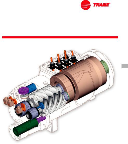
The Model RTAC chiller uses the proven design of theTrane helical-rotary compressor, which embraces all of the design features that have made the Trane helical-rotary compressor liquid chillers such a success since 1987.
What Is New
The RTAC offers the same high reliability coupled with greatly improved energy efficiency, vastly reduced physical footprint, and improved acoustical performance, due to its advanced design, low-speed, directdrive compressor, and proven
Series R™ performance.
The major differences between the Series R, Model RTAC and Model RTAA are:
•Smaller physical footprint
•Lower sound levels
•Higher energy efficiency
•Designed specifically for operating with environmentally-safe HFC-134a.
The Series R Model RTAC helical-rotary chiller is an industrial-grade design, built for both the industrial and commercial markets. It is ideal for schools, hospitals, retailers, office buildings, and industrial applications.
Figure 1
©American Standard Inc. 2000 |
RLC-PRC005-E4 |

Contents
Introduction |
2 |
|
Features and Benefits |
|
|
4 |
||
|
|
|
Improved Acoustical Performance |
5 |
|
Simple Installation |
|
|
6 |
||
Superior Control withTracer™ Chiller Controls |
|
|
7 |
||
Options |
|
|
8 |
||
Application Considerations |
|
|
9 |
||
Selection Procedure |
|
|
12 |
||
General Data |
|
|
13 |
||
Performance Data |
|
|
19 |
||
Performance Adjustment Factors |
|
|
33 |
||
Controls |
|
|
36 |
||
|
|
|
Generic Building Automation System Controls |
36 |
|
TypicalWiring Diagrams |
|
|
39 |
||
Job Site Data |
|
|
44 |
||
Electrical Data |
|
|
45 |
||
Dimensional Data |
|
|
47 |
||
Mechanical Specifications |
|
|
50 |
RLC-PRC005-E4 |
3 |
Features and
Benefits
|
Water Chiller Systems Business Unit |
The Series R™ |
||
|
|
|
|
Helical-Rotary Compressor |
|
|
|
|
• Unequaled reliability.The next |
|
|
|
|
|
|
|
|
|
generationTrane helical-rotary |
|
|
|
|
compressor is designed, built, and |
|
|
|
|
tested to the same demanding and |
|
|
|
|
|
|
|
|
|
rugged standards as theTrane scroll |
|
|
|
|
compressors, the centrifugal |
|
|
|
|
compressors, and the previous |
|
|
|
|
generation helical-rotary compressors |
|
|
|
|
used in both airand water-cooled |
|
|
|
|
chillers for more than 13 years. |
|
|
|
|
• Years of research and testing.The |
|
|
|
|
Trane helical-rotary compressor has |
|
|
|
|
amassed thousands of hours of |
|
|
|
|
testing, much of it at severe operating |
|
|
|
|
conditions beyond normal commercial |
|
|
|
|
air-conditioning applications. |
|
|
|
|
• Proven track record.TheTrane |
|
|
|
|
Company is the world’s largest |
|
|
|
|
manufacturer of large helical-rotary |
|
|
|
|
compressors used for refrigeration. |
|
|
|
|
Over 90,000 compressors worldwide |
|
|
|
|
have proven that theTrane helical- |
|
|
|
|
rotary compressor has a reliability rate |
|
|
|
|
of greater than 99.5 percent in the first |
|
|
|
|
year of operation—unequalled in the |
|
|
|
|
industry. |
•Resistance to liquid slugging.The robust design of the Series R compressor can ingest amounts of liquid refrigerant that normally would severely damage reciprocating compressor valves, piston rods, and cylinders.
•Fewer moving parts.The helical-rotary compressor has only two rotating parts: the male rotor and the female rotor. Unlike reciprocating compressors, theTrane helical-rotary compressor has no pistons, connecting rods, suction and discharge valves, or mechanical oil pump. In fact, a typical reciprocating compressor has 15 times as many critical parts as the Series R compressor. Fewer moving parts leads to increased reliability and longer life.
•Direct-drive, low-speed, semi-hermetic compressor for high efficiency and high reliability.
•Field-serviceable compressor for easy maintenance.
•Suction-gas-cooled motor.The motor operates at lower temperatures for longer motor life.
•Five minute start-to-start and two minute stop-to-start anti-recycle timer allows for closer water-loop temperature control.
4 |
RLC-PRC005-E4 |
Improved
Acoustical
Performance
Figure 2 — Cutaway of a compressor
The sound levels of the Series R Model RTAA have been steadily improved since its introduction.With the advent of the Model RTAC, sound levels are reduced significantly by addressing two major sources: the compressor and the refrigerant piping. First, the compressor has been specifically designed to minimize sound generation. Second, the refrigerant components and piping have been optimized to reduce sound propagation throughout the system.The result: sound levels achieved on the Model RTAC represent the lowest sound levels ever onTrane air-cooled helicalrotary compressor water chillers.
Superior Efficiency Levels:
The Bar Has Been Raised
The standard-efficiencyTrane Model RTAC has COP levels up to 2.90 kW/kW [9.9 EER] (including fans), while the premium-efficiency, or high-efficiency, units leap to COP levels of 3.08 kW/kW [10.51 EER] (including fans).
The modern technology of the RTAC with the efficient direct-drive compressor, the flooded evaporator, the unique design to separate liquid and vapor, the electronic expansion valve, and the revolutionaryTracer™ Chiller Controls, has permittedTrane to achieve these efficiency levels, unmatched in the industry.
Precise RotorTip Clearances
Higher energy efficiency in a helicalrotary compressor is obtained by reducing the rotor tip clearances.This next-generation compressor is no exception.With today’s advanced manufacturing technology, clearances can be controlled to even tighter tolerances.This reduces the leakage between highand low-pressure cavities during compression, allowing for more efficient compressor operation.
Capacity Control and Load Matching
The combination patented unloading system onTrane helical-rotary compressors uses the variable
unloading valve for the majority of the unloading function.This allows the compressor to modulate infinitely, to exactly match building load and to maintain chilled-water supply temperatures within ± 0.3°C [±0.5°F] of the set point. Reciprocating and helicalrotary chillers that rely on stepped capacity control must run at a capacity equal to or greater than the load, and typically can only maintain water temperature to around ± 1°C [±2°F]. Much of this excess capacity is lost because overcooling goes toward removing building latent heat, causing the building to be dried beyond normal comfort requirements.When the load becomes very low, the compressor also uses a step unloader valve, which is a single unloading step to achieve the minimum unloading point of the compressor.The result of this design is optimized part-load performance far superior to single reciprocating compressors and step-only helicalrotary compressors.
RLC-PRC005-E4 |
5 |
Simple Installation
Compact Physical Size
TheTrane Model RTAC chiller averages a 20 percent reduction in physical footprint, while the greatest change is actually 40 percent smaller when compared against the previous design. This improvement makes the RTAC the smallest air-cooled chiller in the industry and a prime candidate for installations that have space constraints. All physical sizes were changed without sacrificing the side clearances needed to supply fresh airflow without coil starvation—the tightest operational clearances in the industry.
Close Spacing Installation
The air-cooled Series R™ chiller has the tightest recommended side clearance in the industry, 1.2 meters, but that is not all. In situations where equipment must be installed with less clearance than recommended, which frequently occurs in retrofit applications, restricted airflow is common. Conventional chillers may not work at all. However, the air-cooled Series R chiller with the Adaptive Control™ microprocessor will make as much chilled water as possible given the actual installed conditions, stay on-line during any unforeseen abnormal conditions, and optimize its performance. Consult yourTrane sales engineer for more details.
Factory estingMeans rouble-Free Start-up
All air-cooled Series R chillers are given a complete functional test at the factory. This computer-based test program completely checks the sensors, wiring, electrical components, microprocessor function, communication capability, expansion valve performance, and fans. In addition, each compressor is runtested to verify capacity and efficiency. Where applicable, each unit is factory preset to the customer’s design conditions. An example would be the leaving-liquid temperature set point.The result of this test program is that the chiller arrives at the job site fully tested and ready for operation.
Factory-Installedand estedControls and Options Speed Installation
All Series R chiller options, including main power-supply disconnect, low ambient control, ambient temperature sensor, low ambient lockout, communication interface and icemaking controls are factory installed and tested. Some manufacturers send accessories in pieces to be field installed.WithTrane, the customer saves on installation expense and has assurance that ALL chiller controls and options have been tested and will function as expected.
6 |
RLC-PRC005-E4 |
Superior Control with Tracer™ Chiller Controls
The End of Nuisance
Trip-Outsand
Unnecessary Service Calls?
The Adaptive Control™ microprocessor system enhances the air-cooled Series R chiller by providing the very latest chiller control technology.With the Adaptive Control microprocessor, unnecessary service calls and unhappy tenants are avoided.The unit does not nuisance-trip or unnecessarily shut down. Only when theTracer chiller controls have exhausted all possible corrective actions, and the unit is still violating an operating limit, will the chiller shut down. Controls on other equipment typically shut down the chiller, usually just when it is needed the most.
For Example:
A typical five-year-old chiller with dirty coils might trip out on high-pressure cutout on a 38°C [100°F] day in August. A hot day is just when comfort cooling is needed the most. In contrast, the aircooled Series R chiller with an Adaptive Control microprocessor will stage fans on, modulate the electronic expansion valve, and modulate the slide valve as it approaches a high-pressure cutout, thereby keeping the chiller on line when you need it the most.
System Options: Ice Storage
Trane air-cooled chillers are well-suited for ice production.The unique ability to operate at decreased ambient temperature while producing ice results in approximately the same amount of work for the compressor. An air-cooled machine typically switches to ice production at night.Two things happen under this assumption. First, the leaving brine temperature from the evaporator
is lowered to around -5.5 to -5°C [22 to 24°F]. Second, the ambient temperature has typically dropped about 8.3 to 11°C [15 to 20°F] from the peak daytime ambient.This effectively places a lift on the compressors that is similar to daytime running conditions.The chiller can operate in lower ambient at night and successfully produce ice to supplement the next day’s cooling demands.
The Model RTAC produces ice by supplying ice storage tanks with a constant supply of glycol solution. Aircooled chillers selected for these lower leaving-fluid temperatures are also selected for efficient production of chilled fluid at nominal comfort-cooling conditions.The ability ofTrane chillers to serve “double duty” in ice production and comfort cooling greatly reduces the capital cost of ice-storage systems.
When cooling is required, ice-chilled glycol is pumped from the ice storage tanks directly to the cooling coils. No expensive heat exchanger is required. The glycol loop is a sealed system, eliminating expensive annual chemical treatment costs.The air-cooled chiller is also available for comfort-cooling duty at nominal cooling conditions and efficiencies.The modular concept of glycol ice-storage systems, and the proven simplicity ofTraneTracer™ controls, allow the successful blend of reliability and energy-saving performance in any ice-storage application.
The ice-storage system is operated in six different modes, each optimized for the utility cost at a particular time of day.
1.Provide comfort cooling with chiller
2.Provide comfort cooling with ice
3.Provide comfort cooling with ice and chiller
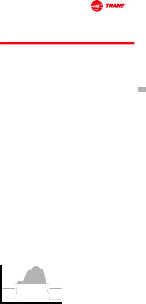
Figure 3 — Ice storage demand cost savings
4.Freeze ice storage
5.Freeze ice storage when comfort cooling is required
6.Off
Tracer optimization software controls operation of the required equipment and accessories to easily move from one mode of operation to another. For example: even with ice-storage systems, there are numerous hours when ice is neither produced nor consumed, but saved. In this mode, the chiller is the sole source of cooling. For example, to cool the building after all ice is produced but before high electrical-demand charges take effect,Tracer sets the aircooled chiller leaving-fluid set point to its most efficient setting and starts the chiller, chiller pump, and load pump.
When electrical demand is high, the ice pump is started and the chiller is either demand limited or shut down completely.Tracer controls have the intelligence to optimally balance the contribution of the ice and the chiller in meeting the cooling load.
The capacity of the chiller plant is extended by operating the chiller and ice in tandem.Tracer rations the ice, augmenting chiller capacity while reducing cooling costs.When ice is produced,Tracer will lower the aircooled chiller leaving-fluid set point and start the chiller, ice and chiller pumps, and other accessories. Any incidental loads that persists while producing ice can be addressed by starting the load pump and drawing spent cooling fluid from the ice storage tanks.
For specific information on ice storage applications, contact your localTrane sales office.
LOAD |
|
|
|
ICE |
|
|
CHILLER |
|
MN |
6 A.M. NOON |
6 P.M. MN |
RLC-PRC005-E4 |
|
7 |
Options
Premium Efficiency and
Performance Option
This option provides oversized heat exchangers with two purposes. One, it allows the unit to be more energy efficient.Two, the unit will have enhanced operation in high-ambient conditions.
Low-TemperatureBrine
The hardware and software on the unit are factory set to handle lowtemperature brine applications, typically below 5°C [41°F].
Ice Making
The unit controls are factory set to handle ice making for thermal storage applications.
TracerSummit™Communication
Interface
Permits bi-directional communication to theTrane Integrated Comfort™ system.
Remote Input Options
Permits remote chilled-liquid set point, remote current-limit set point, or both, by accepting a 4-20 mA or 2-10VDC analog signal.
Remote Output Options
Permits alarm relay outputs, ice-making outputs, or both.
Chilled-Water Reset
This option provides the control logic and field-installed sensors to reset leaving-chilled-water temperature.The set point can be reset based on either ambient temperature or return evaporator-water temperature.
Protection Grilles
Protection grilles cover the complete condensing coils and the service areas beneath the coils.
Coil Protection
A coated wire mesh that covers the condenser coils only.
Access Protection
A coated wire mesh that covers the access area underneath the condenser coils.
ServiceValves
Provides a service valve on the suction and discharge lines of each circuit to facilitate compressor servicing.
High-Ambient Option
The high-ambient option consists of special control logic to permit highambient (up to 52°C [125°F]) operation. This option offers the best performance when coupled with the premium efficiency and performance option.
Low-Ambient Option
The low-ambient option consists of special control logic and fans to permit low-ambient (down to -23°C [-9°F]) operation.
Low-Ambient Lockout
A factory-installed ambient sensor and control logic will prevent starting below the recommended ambient temperature.
Power Disconnect Switch
A disconnect switch with a through-the- door handle, plus compressor protection fuses, is provided to disconnect main power.
Night Noise Setback
At night, on contact closure all the fans run at low speed, bringing the overall sound level further down.
SCR (Short-Circuit Rating)
Offers a measure of safety for what the starter-panel enclosure is able to withstand in the event of an explosion caused by a short circuit; protection up to 35,000 amps is available on most voltages.
Neoprene Isolators
Isolators provide isolation between the chiller and the structure to help eliminate vibration transmission. Neoprene isolators are more effective and recommended over spring isolators.
Victaulic Connection Kit
Provides a kit that includes a set of two pipe stubs andVictaulic couplings.
Low NoiseVersion
The unit is equipped with low-speed fans and a compressor soundattenuating enclosure. All the sound-emitting parts, like refrigerant lines and panels subject to vibration, are acoustically treated with soundabsorbent material.
Evaporator Freeze Protection
Factory-installed and -wired trace heaters on the water boxes and on the intermediate tube plate, with an ambient thermostat and protected by a circuit breaker.
Ground Fault Detection
Sensing ground current for improved chiller protection.
8 |
RLC-PRC005-E4 |
Application Considerations
Certain application constraints should be considered when sizing, selecting, and installingTrane air-cooled Series R chillers. Unit and system reliability is often dependent on properly and completely complying with these considerations.When the application varies from the guidelines presented, it should be reviewed with your local Trane sales engineer.
Unit Sizing
Unit capacities are listed in the performance data section. Intentionally oversizing a unit to ensure adequate capacity is not recommended. Erratic system operation and excessive compressor cycling are often a direct result of an oversized chiller. In addition, an oversized unit is usually more expensive to purchase, install, and operate. If oversizing is desired, consider using two units.
Water reatment
Dirt, scale, products of corrosion, and other foreign material will adversely affect heat transfer between the water and system components. Foreign matter in the chilled-water system can also increase pressure drop and, consequently, reduce water flow. Proper water treatment must be determined locally, depending on the type of system
and local water characteristics. Neither salt nor brackish water is recommended for use inTrane air-cooled Series R chillers. Use of either will lead to a shortened chiller life.TheTrane Company encourages the employment of a reputable water-treatment specialist, familiar with local water conditions, to assist in this determination and in the establishment of a proper watertreatment program.
Effect of Altitude on Capacity
Air-cooled Series R chiller capacities given in the performance data tables are for use at sea level. At elevations substantially above sea level, the decreased air density will reduce condenser capacity and, therefore, unit capacity and efficiency.The adjustment factors inTable F-1 can be applied directly to the catalog performance data to determine the unit’s adjusted performance.
Ambient Limitations
Trane air-cooled Series R chillers are designed for year-round operation over a range of ambient temperatures.The air-cooled Model RTAC chiller will operate in ambient temperatures of 4 to 46°C [25 to 115°F]. Selecting the highambient option will allow the chiller to operate in ambient temperatures of
51°C [125°F], and selecting the lowambient option will increase the operational capability of the water chiller to ambient temperatures as low as 18°C [0°F]. For operation outside of these ranges, contact the localTrane sales office.
Water Flow Limits
The minimum water flow rates are given inTables G-1 and G-2. Evaporator flow rates below the tabulated values will result in laminar flow and cause freeze-up problems, scaling, stratification, and poor control.The maximum evaporator water flow rate is also given in the general data section. Flow rates exceeding those listed may result in excessive tube erosion.
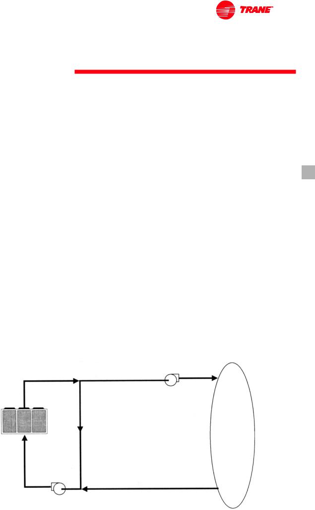
Flow Rates Out of Range
Many process cooling jobs require flow rates that cannot be met with the minimum and maximum published values within the Model RTAC evaporator. A simple piping change can alleviate this problem. For example: a plastic injection molding process requires 5.0 Lps [80 gpm] of 10°C [50°F] water and returns that water at 15.6°C [60°F].The selected chiller can operate at these temperatures, but has a minimum flow rate of 7.6 Lps [120 gpm].The following system can satisfy the process.
Figure 4 — GPM Out of Range |
10°C |
|
|
5 Lps |
|
10°C |
CV Pump |
|
7.6 Lps |
||
5 Lps |
||
|
|
|
Load |
|
|
10°C |
|
|
2.5 Lps |
|
13.7°C |
|
|
7.6 Lps |
|
|
CV pump |
15.6°C |
|
5 Lps |
|
|
7.5 Lps |
|
|
|
|
RLC-PRC005-E4 |
|
9 |
Application Considerations
Figure 5 — GPM Out of Range |
15.6°C |
29.4°C |
|
2.2 Lps |
7.6 Lps |
15.6°C |
|
CV Pump |
7.6 Lps |
|
|
|
|
Load
|
15°C |
35°C |
|
5.4 Lps |
5.4 Lps |
21°C 7.6 Lps
CV Pump |
35°C |
35°C |
|
7.6 Lps |
|||
2.2 Lps |
|||
|
|||
|
|
Leaving-WaterTemperature Range
Trane air-cooled Series R chillers have three distinct leaving-water categories: standard, low temperature, and ice making.The standard leaving-solution temperature range is 4.4 to 15.6°C [40 to 60°F]. Low-temperature machines produce leaving-liquid temperatures less than 4.4°C [40°F]. Since liquid supply temperature set points less than 4.4°C [40°F] result in suction temperatures at or below the freezing point of water, a glycol solution is required for all low-temperature machines. Ice-making machines have a leaving-liquid temperature range of -6.7 to 15.6°C [20 to 60°F]. Ice-making controls include dual set point controls and safeties for ice making and standard cooling capabilities. Consult your local Trane sales engineer for applications or selections involving low temperature or ice making machines.The maximum water temperature that can be circulated through an evaporator when the unit is not operating is 42°C [108°F].
Leaving-WaterTemperature
Out of Range
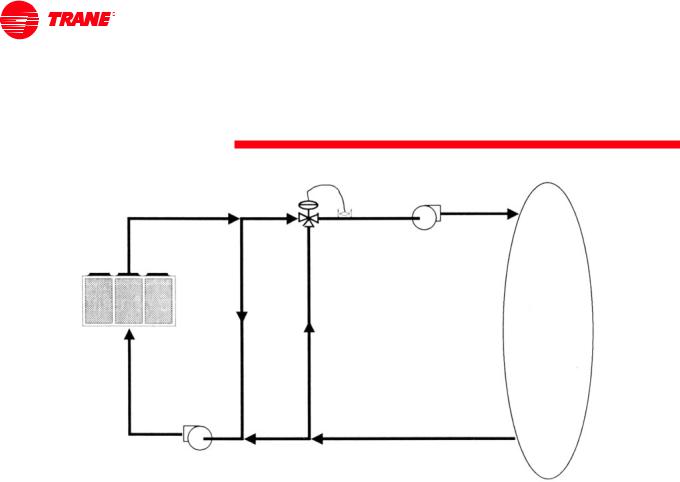
Similar to the flow rates above, many process cooling jobs require temperature ranges that cannot be met with the minimum and maximum published values for the Model RTAC evaporator. A simple piping change can alleviate this problem. For example: a laboratory load requires 7.6 Lps [120 gpm] of water entering the process at
29.4°C [85°F] and returning at 35°C [95°F].The accuracy required is higher than the cooling tower can give.The selected chiller has adequate capacity, but has a maximum leaving-chilled- water temperature of 15.6°C [60°F].
In the example shown, both the chiller and process flow rates are equal.This is not necessary. For example, if the chiller had a higher flow rate, there would be more water bypassing and mixing with warm water.
Supply-WaterTemperature Drop
The performance data for theTrane aircooled Series R chiller is based on a chilled-water temperature drop of 6°C [10.8°F]. Chilled-water temperature drops from 3.3 to 10°C [6 to 18°F] may be used as long as minimum and maximum water temperature, and minimum and maximum flow rates, are not violated.Temperature drops outside this range are beyond the optimum range for control, and may adversely affect the microcomputer’s ability to maintain an acceptable supply-water temperature range. Further, temperature drops of less than 3.3°C [6°F] may result in inadequate refrigerant superheat. Sufficient superheat is always a primary concern in any direct-expansion refrigerant system and is especially important in a package chiller where the evaporator is closely coupled to the compressor.When temperature drops are less than 3.3°C [6°F], an evaporator runaround loop may be required.
10 |
RLC-PRC005-E4 |
Application Considerations
Variable Flow in the Evaporator
An attractive chilled-water system option may be a variable primary flow (VPF) system.VPF systems present building owners with several costsaving benefits that are directly related to the pumps.The most obvious cost savings result from eliminating the secondary distribution pump, which in turn avoids the expense incurred with the associated piping connections (material, labor), electrical service, and variable-frequency drive. Building owners often cite pump-related energy savings as the reason that prompted them to install aVPF system.With the help of a software analysis tool such as System Analyzer™,TRACE™, or DOE-2, you can determine whether the anticipated energy savings justify the use of variable primary flow in a particular application. It may also be easier to apply variable primary flow in an existing chilled-water plant. Unlike the “decoupled” design, the bypass can be positioned at various points in the chilled-water loop and an additional pump is unnecessary.The evaporator in the Model RTAC can withstand up to 50 percent water flow reduction as long as this flow is equal to or above the minimum flow-rate requirements.The microprocessor and capacity control algorithms are designed to take a minimum of 10 percent change in water flow rate per minute.
Ice Storage Provides
Reduced Electrical Demand
An ice-storage system uses a standard chiller to make ice at night, when utilities charge less for electricity.The ice supplements, or even replaces, mechanical cooling during the day, when utility rates are at their highest. This reduced need for cooling results in big utility cost savings.
Another advantage of ice storage is standby cooling capacity. If the chiller is unable to operate, one or two days of ice may still be available to provide cooling. In that period of time, the chiller can be repaired before building occupants feel any loss of comfort.
TheTrane Model RTAC chiller is uniquely suited to low-temperature applications like ice storage because of the ambient relief experienced at night.This allows the Model RTAC chiller to produce ice efficiently, with less stress on the machine.
Simple and smart control strategies are another advantage the Model RTAC chiller offers for ice-storage applications. TraneTracer™ building management systems can actually anticipate how much ice needs to be made at night, and operate the system accordingly.The controls are integrated right into the chiller.Two wires and preprogrammed software dramatically reduce field installation cost and complex programming.
ShortWater Loops
The proper location of the temperature control sensor is in the supply (outlet) water connection or pipe.This location allows the building to act as a buffer and assures a slowly-changing return-water temperature. If there is not a sufficient volume of water in the system to provide an adequate buffer, temperature control can be lost, resulting in erratic system operation and excessive compressor cycling. A short water loop has the same effect as attempting to control using the building return water. Typically, a two-minute water loop is sufficient to prevent a short water loop. Therefore, as a guideline, ensure that the volume of water in the evaporator loop equals or exceeds two times the evaporator flow rate. For a rapidly changing load profile, the amount of volume should be increased.To prevent the effect of a short water loop, the following item should be given careful consideration: a storage tank or larger header pipe to increase the volume of water in the system and, therefore, reduce the rate of change of the return water temperature.
ApplicationsTypes
•Comfort cooling
•Industrial process cooling
•Ice or thermal storage
•Low-temperature process cooling.
RLC-PRC005-E4 |
11 |
Selection Procedure
The chiller capacity tables cover the most frequently encountered leavingliquid temperatures.The tables reflect a 6°C [10.8°F] temperature drop through the evaporator. For other temperature drops, apply the appropriate performance data adjustment factors. For chilled brine selections, refer to Figures F-3 and F-4 for ethylene and propylene glycol adjustment factors.
To select aTrane air-cooled Series R™ chiller, the following information is required:
Selection Procedure SI Units
The chiller capacity tables P-1 through P-4 cover the most frequently encountered leaving-water temperatures.The tables reflect a 6°C temperature drop through the evaporator
To select aTrane air-cooled RTAC chiller, the following information is required:
1
Design load in kW of refrigeration
2
Design chilled-water temperature drop
3
Design leaving-chilled-water temperature
4
Design ambient temperature
Evaporator flow rates can be determined by using the following formula:
Lps = kW (capacity) x 0.239 ÷ temperature drop (°C)
To determine the evaporator pressure drop we use the flow rate (Lps) and the evaporator water pressure drop Figure F1.
For selection of chilled brine units, or applications where the altitude is significantly greater than sea level or the temperature drop is different than 6°C, the performance adjustment factors fromTable F-1 should be applied at this point.
For example:
Corrected Capacity = Capacity
(unadjusted) x Glycol Capacity
Adjustment Factor
Corrected Flow Rate = Flow Rate
(unadjusted) x Glycol Flow Rate
Adjustment Factor
5
The final unit selection is:
•Quantity (1) RTAA 140
•Cooling capacity = 505.9 kW
•Design ambient temperature 35°C
•Entering chilled-water temperatures = 12°C
•Leaving chilled-water temperatures = 7°C
•Chilled-water flow rate = 24.2 Lps
•Evaporator water pressure drop = 53 kPa
•Compressor power input = 159 kW
•Unit COP = 2.9 kW/kW
Contact the localTrane sales engineer for a proper selection at the given operating conditions.
For a selection in English units:
•1 ton = 3.5168 kW
•Evaporator flow rate in gpm = 24 x tons ÷ deltaT (°F)
•DeltaT (°F) = deltaT (°C) x 1.8
•1 gpm = 0.06309 Lps
•1 ftWG = 3 kPa
•EER = COP ÷ 0.293
12 |
RLC-PRC005-E4 |
General Data
SI Units
Table G-1 — RTAC Standard
Size |
|
140 |
155 |
170 |
185 |
200 |
|
|
Compressor |
|
|
|
|
|
|
|
|
Quantity |
|
2 |
2 |
2 |
2 |
2 |
|
|
Nominal Size (1) |
tons |
70/70 |
70/85 |
85/85 |
85/100 |
100/100 |
|
|
Evaporator |
|
|
|
|
|
|
|
|
Evaporator Model |
|
F140 |
F155 |
F170 |
F185 |
F200 |
|
|
Water Storage |
L |
132.3 |
141.3 |
150.7 |
156 |
163.5 |
|
|
Minimum Flow |
Lps |
10.8 |
11.5 |
12.5 |
13.6 |
13.6 |
|
|
Maximum Flow |
Lps |
33.1 |
38.2 |
43.1 |
39.5 |
48.4 |
|
|
Condenser |
|
|
|
|
|
|
|
|
Qty of Coils |
|
4 |
4 |
4 |
4 |
4 |
|
|
Coil Length |
mm |
3962/3962 |
4572/3962 |
4572/4572 |
5486/4572 |
5486/5486 |
|
|
Coil Height |
mm |
1067 |
1067 |
1067 |
1067 |
1067 |
|
|
Fin series |
fins/ft |
192 |
192 |
192 |
192 |
192 |
|
|
Number of Rows |
|
3 |
3 |
3 |
3 |
3 |
|
|
Condenser Fans |
|
|
|
|
|
|
|
|
|
|
|
|
|
|
|
|
|
Quantity (1) |
|
4/4 |
5/4 |
5/5 |
6/5 |
6/6 |
|
|
Diameter |
mm |
762 |
762 |
762 |
762 |
762 |
|
|
Total Air Flow |
m3/s |
35.82 |
39.53 |
43.22 |
47.55 |
51.88 |
|
|
Nominal RPM |
|
915 |
915 |
915 |
915 |
915 |
|
|
Tip Speed |
m/s |
36.48 |
36.48 |
36.48 |
36.48 |
36.48 |
|
|
Motor kW |
kW |
1.9 |
1.9 |
1.9 |
1.9 |
1.9 |
|
|
Min Starting/Operating Ambient(2) |
|
|
|
|
|
|
|
|
Standard Unit |
°C |
-4 |
-4 |
-4 |
-4 |
-4 |
|
|
Low-Ambient Unit |
°C |
-23 |
-23 |
-23 |
-23 |
-23 |
|
|
General Unit |
|
|
|
|
|
|
|
|
Refrigerant |
|
HFC 134a |
HFC 134a |
HFC 134a |
HFC 134a |
HFC 134a |
|
|
Number of Independent |
|
|
|
|
|
|
|
|
Refrigerant Circuits |
|
2 |
2 |
2 |
2 |
2 |
|
|
% Minimum Load (3) |
|
15 |
15 |
15 |
15 |
15 |
|
|
Refrigerant Charge (1) |
kg |
65.8/65.8 |
70.3/65.8 |
70.3/70.3 |
99.8/95.3 |
99.8/99.8 |
|
|
Oil Charge (1) |
L |
7.6/7.6 |
7.6/7.6 |
7.6/7.6 |
9.9/7.6 |
9.9/9.9 |
|
|
Operating Weight |
kg |
5216 |
5407 |
5586 |
6268 |
6396 |
|
|
Shipping Weight |
kg |
5107 |
5265 |
5434 |
6111 |
6232 |
|
|
Table G-2 — RTAC High Efficiency
Size |
|
120 |
130 |
140 |
155 |
170 |
185 |
200 |
Compressor |
|
|
|
|
|
|
|
|
Quantity |
|
2 |
2 |
2 |
2 |
2 |
2 |
2 |
Nominal Size (1) |
tons |
60/60 |
60/70 |
70/70 |
70/85 |
85/85 |
85/100 |
100/100 |
Evaporator |
|
|
|
|
|
|
|
|
Evaporator Model |
|
F140 |
F155 |
F170 |
F185 |
F200 |
F220 |
F240 |
Water Storage |
L |
132.3 |
141.3 |
150.7 |
156 |
163.5 |
175.9 |
188.3 |
Minimum Flow |
Lps |
10.8 |
11.5 |
12.5 |
13.6 |
13.6 |
14.9 |
16.3 |
Maximum Flow |
Lps |
33.1 |
38.2 |
43.3 |
39.5 |
48.4 |
53.5 |
58.6 |
Condenser |
|
|
|
|
|
|
|
|
Qty of Coils |
|
4 |
4 |
4 |
4 |
4 |
4 |
4 |
Coil Length |
mm |
3962/3962 |
4572/3962 |
4572/4572 |
5486/4572 |
5486/5486 |
6400/2486 |
6400/6400 |
Coil Height |
mm |
1067 |
1067 |
1067 |
1067 |
1067 |
1067 |
1067 |
Fin series |
fins/ft |
192 |
192 |
192 |
192 |
192 |
192 |
192 |
Number of Rows |
|
3 |
3 |
3 |
3 |
3 |
3 |
3 |
Condenser Fans |
|
|
|
|
|
|
|
|
Quantity (1) |
|
4/4 |
5/4 |
5/5 |
6/5 |
6/6 |
7/6 |
7/7 |
Diameter |
mm |
762 |
762 |
762 |
762 |
762 |
762 |
762 |
Total Air Flow |
m3/s |
35.82 |
39.53 |
43.22 |
47.55 |
51.88 |
56.17 |
60.47 |
Nominal RPM |
|
915 |
915 |
915 |
915 |
915 |
915 |
915 |
Tip Speed |
m/s |
36.48 |
36.48 |
36.48 |
36.48 |
36.48 |
36.48 |
36.48 |
Motor kW |
kW |
1.9 |
1.9 |
1.9 |
1.9 |
1.9 |
1.9 |
1.9 |
Min Starting/Operating Ambient(2) |
|
|
|
|
|
|
|
|
Standard Unit |
°C |
-4 |
-4 |
-4 |
-4 |
-4 |
-4 |
-4 |
Low-Ambient Unit |
°C |
-23 |
-23 |
-23 |
-23 |
-23 |
-23 |
-23 |
General Unit |
|
|
|
|
|
|
|
|
Refrigerant |
|
HFC 134a |
HFC 134a |
HFC 134a |
HFC 134a |
HFC 134a |
HFC 134a |
HFC 134a |
Number of Independent |
|
|
|
|
|
|
|
|
Refrigerant Circuits |
|
2 |
2 |
2 |
2 |
2 |
2 |
2 |
% Minimum Load (3) |
|
15 |
15 |
15 |
15 |
15 |
15 |
15 |
Refrigerant Charge (1) |
kg |
65.8/65.8 |
70.3/65.8 |
70.3/70.3 |
99.8/95.3 |
99.8/99.8 |
104.4/99.8 |
104.4/104.4 |
Oil Charge (1) |
L |
7.6/7.6 |
7.6/7.6 |
7.6/7.6 |
7.6/7.6 |
7.6/7.6 |
9.9/7.6 |
9.9/9.9 |
Operating Weight |
kg |
5198 |
5271 |
5274 |
6073 |
6323 |
6555 |
6759 |
Shipping Weight |
kg |
5089 |
5129 |
5122 |
5916 |
6159 |
6378 |
6569 |
RLC-PRC005-E4 |
|
|
|
|
|
|
|
13 |
General Data
SI Units
Table G-3 — RTAC Low Noise Standard
|
|
Size |
|
140 |
155 |
170 |
185 |
200 |
|
|
Compressor |
|
|
|
|
|
|
|
|
Quantity |
|
2 |
2 |
2 |
2 |
2 |
|
|
Nominal Size (1) |
tons |
70/70 |
70/85 |
85/85 |
85/100 |
100/100 |
|
|
Evaporator |
|
|
|
|
|
|
|
|
Evaporator Model |
|
F140 |
F155 |
F170 |
F185 |
F200 |
|
|
Water Storage |
L |
132.3 |
141.3 |
150.7 |
156 |
163.5 |
|
|
Minimum Flow |
Lps |
10.8 |
11.5 |
12.5 |
13.6 |
13.6 |
|
|
Maximum Flow |
Lps |
33.1 |
38.2 |
43.1 |
39.5 |
48.4 |
|
|
Condenser |
|
|
|
|
|
|
|
|
Qty of Coils |
|
4 |
4 |
4 |
4 |
4 |
|
|
Coil Length |
mm |
3962/3962 |
4572/3962 |
4572/4572 |
5486/4572 |
5486/5486 |
|
|
Coil Height |
mm |
1067 |
1067 |
1067 |
1067 |
1067 |
|
|
Fin series |
fins/ft |
192 |
192 |
192 |
192 |
192 |
|
|
Number of Rows |
|
3 |
3 |
3 |
3 |
3 |
|
|
Condenser Fans |
|
|
|
|
|
|
|
|
Quantity (1) |
|
4/4 |
5/4 |
5/5 |
6/5 |
6/6 |
|
|
Diameter |
mm |
762 |
762 |
762 |
762 |
762 |
|
|
Total Air Flow |
m3/s |
25.61 |
28.27 |
30.93 |
34.02 |
37.11 |
|
|
Nominal RPM |
|
680 |
680 |
680 |
680 |
680 |
|
|
Tip Speed |
m/s |
27.5 |
27.5 |
27.5 |
27.5 |
27.5 |
|
|
Motor kW |
kW |
0.85 |
0.85 |
0.85 |
0.85 |
0.85 |
|
|
Min Starting/Operating Ambient(2) |
|
|
|
|
|
|
|
|
Standard Unit |
°C |
-4 |
-4 |
-4 |
-4 |
-4 |
|
|
Low-Ambient Unit |
°C |
-23 |
-23 |
-23 |
-23 |
-23 |
|
|
General Unit |
|
|
|
|
|
|
|
|
Refrigerant |
|
HFC 134a |
HFC 134a |
HFC 134a |
HFC 134a |
HFC 134a |
|
|
Number of Independent |
|
|
|
|
|
|
|
|
Refrigerant Circuits |
|
2 |
2 |
2 |
2 |
2 |
|
|
% Minimum Load (3) |
|
15 |
15 |
15 |
15 |
15 |
|
|
Refrigerant Charge (1) |
kg |
65.8/65.8 |
70.3/65.8 |
70.3/70.3 |
99.8/95.3 |
99.8/99.8 |
|
|
Oil Charge (1) |
L |
7.6/7.6 |
7.6/7.6 |
7.6/7.6 |
9.9/7.6 |
9.9/9.9 |
|
|
Operating Weight |
kg |
5306 |
5497 |
5676 |
6358 |
6486 |
|
|
Shipping Weight |
kg |
5197 |
5355 |
5524 |
6201 |
6322 |
14 |
RLC-PRC005-E4 |
General Data
SI Units
Table G-4 — RTAC High Efficiency Low Noise
Size |
|
120 |
130 |
140 |
155 |
170 |
185 |
200 |
|
|
Compressor |
|
|
|
|
|
|
|
|
|
|
Quantity |
|
2 |
2 |
2 |
2 |
2 |
2 |
2 |
|
|
Nominal Size (1) |
tons |
60/60 |
60/70 |
70/70 |
70/85 |
85/85 |
85/100 |
100/100 |
|
|
Evaporator |
|
|
|
|
|
|
|
|
|
|
Evaporator Model |
|
F140 |
F155 |
F170 |
F185 |
F200 |
F220 |
F240 |
|
|
Water Storage |
L |
132.3 |
141.3 |
150.7 |
156 |
163.5 |
175.9 |
188.3 |
|
|
Minimum Flow |
Lps |
10.8 |
11.5 |
12.5 |
13.6 |
13.6 |
14.9 |
16.3 |
|
|
Maximum Flow |
Lps |
33.1 |
38.2 |
43.3 |
39.5 |
48.4 |
53.5 |
58.6 |
|
|
Condenser |
|
|
|
|
|
|
|
|
|
|
Qty of Coils |
|
4 |
4 |
4 |
4 |
4 |
4 |
4 |
|
|
Coil Length |
mm |
3962/3962 |
4572/3962 |
4572/4572 |
5486/4572 |
5486/5486 |
6400/2486 |
6400/6400 |
|
|
Coil Height |
mm |
1067 |
1067 |
1067 |
1067 |
1067 |
1067 |
1067 |
|
|
Fin series |
fins/ft |
192 |
192 |
192 |
192 |
192 |
192 |
192 |
|
|
Number of Rows |
|
3 |
3 |
3 |
3 |
3 |
3 |
3 |
|
|
Condenser Fans |
|
|
|
|
|
|
|
|
|
|
Quantity (1) |
|
4/4 |
5/4 |
5/5 |
6/5 |
6/6 |
7/6 |
7/7 |
|
|
Diameter |
mm |
762 |
762 |
762 |
762 |
762 |
762 |
762 |
|
|
Total Air Flow |
m3/s |
25.61 |
28.27 |
30.93 |
34.02 |
37.11 |
40.23 |
43.34 |
|
|
Nominal RPM |
|
680 |
680 |
680 |
680 |
680 |
680 |
680 |
|
|
Tip Speed |
m/s |
27.5 |
27.5 |
27.5 |
27.5 |
27.5 |
27.5 |
27.5 |
|
|
Motor kW |
kW |
0.85 |
0.85 |
0.85 |
0.85 |
0.85 |
0.85 |
0.85 |
|
|
Min Starting/Operating Ambient(2) |
|
|
|
|
|
|
|
|
|
|
Standard Unit |
°C |
-4 |
-4 |
-4 |
-4 |
-4 |
-4 |
-4 |
|
|
Low-Ambient Unit |
°C |
-23 |
-23 |
-23 |
-23 |
-23 |
-23 |
-23 |
|
|
General Unit |
|
|
|
|
|
|
|
|
|
|
Refrigerant |
|
HFC 134a |
HFC 134a |
HFC 134a |
HFC 134a |
HFC 134a |
HFC 134a |
HFC 134a |
|
|
Number of Independent |
|
|
|
|
|
|
|
|
|
|
Refrigerant Circuits |
|
2 |
2 |
2 |
2 |
2 |
2 |
2 |
|
|
% Minimum Load (3) |
|
15 |
15 |
15 |
15 |
15 |
15 |
15 |
|
|
Refrigerant Charge (1) |
kg |
65.8/65.8 |
70.3/65.8 |
70.3/70.3 |
99.8/95.3 |
99.8/99.8 |
104.4/99.8 |
104.4/104.4 |
|
|
Oil Charge (1) |
L |
7.6/7.6 |
7.6/7.6 |
7.6/7.6 |
7.6/7.6 |
7.6/7.6 |
9.9/7.6 |
9.9/9.9 |
|
|
Operating Weight |
kg |
5288 |
5361 |
5364 |
6163 |
6413 |
6645 |
6849 |
|
|
Shipping Weight |
kg |
5179 |
5219 |
5212 |
6006 |
6249 |
6468 |
6659 |
|
|
Notes:
1.Data containing information on two circuits shown as follows: ckt1/ckt2
2.Minimum start-up/operation ambient based on a 2.22 m/s (5mph) wind across the condenser.
3.Percent minimum load is for total machine at 10°C (50°F) ambient and 7°C (44°F) leaving chilled water temperature. Not each individual circuit.
RLC-PRC005-E4 |
15 |
General Data
English Units
Table G-5 — RTAC Standard
|
|
Size |
|
140 |
155 |
170 |
185 |
200 |
|
|
Compressor |
|
|
|
|
|
|
|
|
Quantity |
|
2 |
2 |
2 |
2 |
2 |
|
|
Nominal Size (1) |
tons |
70/70 |
70/85 |
85/85 |
85/100 |
100/100 |
|
|
Evaporator |
|
|
|
|
|
|
|
|
Evaporator Model |
|
F140 |
F155 |
F170 |
F185 |
F200 |
|
|
Water Storage |
gal |
35 |
37.3 |
39.8 |
41.2 |
43.2 |
|
|
Minimum Flow |
gpm |
171.2 |
182.3 |
198.2 |
215.6 |
215.6 |
|
|
Maximum Flow |
gpm |
524.7 |
605.6 |
683.2 |
626.2 |
767.2 |
|
|
Condenser |
|
|
|
|
|
|
|
|
Quantity of Coils |
|
4 |
4 |
4 |
4 |
4 |
|
|
Coil Length |
ft |
13/13 |
15/13 |
15/15 |
18/15 |
18/18 |
|
|
Coil Height |
ft |
3.5 |
3.5 |
3.5 |
3.5 |
3.5 |
|
|
Fin Series |
fins/ft |
192 |
192 |
192 |
192 |
192 |
|
|
Number of Rows |
|
3 |
3 |
3 |
3 |
3 |
|
|
Condenser Fans |
|
|
|
|
|
|
|
|
Quantity (1) |
|
4/4 |
5/4 |
5/5 |
6/5 |
6/6 |
|
|
Diameter |
in. |
30 |
30 |
30 |
30 |
30 |
|
|
Total Air Flow |
cfm |
75867 |
83725 |
91540 |
100710 |
109882 |
|
|
Nominal RPM |
|
915 |
915 |
915 |
915 |
915 |
|
|
Tip Speed |
ft/s |
120 |
120 |
120 |
120 |
120 |
|
|
Motor kW |
kW |
1.9 |
1.9 |
1.9 |
1.9 |
1.9 |
|
|
Minimum Starting/Operating Ambient(2) |
|
|
|
|
|
|
|
|
Standard Unit |
°F |
25 |
25 |
25 |
25 |
25 |
|
|
Low-Ambient Unit |
°F |
-9 |
-9 |
-9 |
-9 |
-9 |
|
|
General Unit |
|
|
|
|
|
|
|
|
Refrigerant |
|
HFC 134a |
HFC 134a |
HFC 134a |
HFC 134a |
HFC 134a |
|
|
Number of Independent |
|
|
|
|
|
|
|
|
Refrigerant Circuits |
|
2 |
2 |
2 |
2 |
2 |
|
|
% Minimum Load (3) |
|
15 |
15 |
15 |
15 |
15 |
|
|
Refrigerant Charge (1) |
lb |
145/145 |
155/145 |
155/155 |
220/210 |
220/220 |
|
|
Oil Charge (1) |
gal |
2/2 |
2.2 |
2.2 |
2.6/2 |
2.6/2.6 |
|
|
Operating Weight |
lb |
12018 |
12459 |
12871 |
14442 |
14737 |
|
|
Shipping Weight |
lb |
11767 |
12131 |
12521 |
14081 |
14359 |
|
|
|
|
|
|
|
|
|
Table G-6 — RTAC High Efficiency
Size |
|
120 |
130 |
140 |
155 |
170 |
185 |
200 |
Compressor |
|
|
|
|
|
|
|
|
Quantity |
|
2 |
2 |
2 |
2 |
2 |
2 |
2 |
Nominal Size (1) |
tons |
60/60 |
60/70 |
70/70 |
70/85 |
85/85 |
85/100 |
100/100 |
Evaporator |
|
|
|
|
|
|
|
|
Evaporator Model |
|
F140 |
F155 |
F170 |
F185 |
F200 |
F220 |
F240 |
Water Storage |
gal |
35 |
37.3 |
39.8 |
41.2 |
43.2 |
46.5 |
49.8 |
Minimum Flow |
gpm |
171.2 |
182.3 |
198.2 |
215.6 |
215.6 |
231.4 |
258.4 |
Maximum Flow |
gpm |
524.7 |
605.6 |
683.2 |
626.2 |
767.2 |
848.1 |
928.9 |
Condenser |
|
|
|
|
|
|
|
|
Quantity of Coils |
|
4 |
4 |
4 |
4 |
4 |
4 |
4 |
Coil Length |
ft |
13/13 |
15/13 |
15/15 |
18/15 |
18/18 |
21/18 |
21/21 |
Coil Height |
ft |
3.5 |
3.5 |
3.5 |
3.5 |
3.5 |
3.5 |
3.5 |
Fin Series |
fins/ft |
192 |
192 |
192 |
192 |
192 |
192 |
192 |
Number of Rows |
|
3 |
3 |
3 |
3 |
3 |
3 |
3 |
Condenser Fans |
|
|
|
|
|
|
|
|
Quantity (1) |
|
4/4 |
5/4 |
5/5 |
6/5 |
6/6 |
7/6 |
7/7 |
Diameter |
in. |
30 |
30 |
30 |
30 |
30 |
30 |
30 |
Total Air Flow |
cfm |
75867 |
83725 |
91540 |
100710 |
109882 |
118968 |
128075 |
Nominal RPM |
|
915 |
915 |
915 |
915 |
915 |
915 |
915 |
Tip Speed |
ft/s |
120 |
120 |
120 |
120 |
120 |
120 |
120 |
Motor kW |
kW |
1.9 |
1.9 |
1.9 |
1.9 |
1.9 |
1.9 |
1.9 |
Minimum Starting/Operating Ambient(2) |
|
|
|
|
|
|
|
|
Standard Unit |
°F |
25 |
25 |
25 |
25 |
25 |
25 |
25 |
Low-Ambient Unit |
°F |
-9 |
-9 |
-9 |
-9 |
-9 |
-9 |
-9 |
General Unit |
|
|
|
|
|
|
|
|
Refrigerant |
|
HFC 134a |
HFC 134a |
HFC 134a |
HFC 134a |
HFC 134a |
HFC 134a |
HFC 134a |
Number of Independent |
|
|
|
|
|
|
|
|
Refrigerant Circuits |
|
2 |
2 |
2 |
2 |
2 |
2 |
2 |
% Minimum Load (3) |
|
15 |
15 |
15 |
15 |
15 |
15 |
15 |
Refrigerant Charge (1) |
lb |
145/145 |
155/145 |
155/155 |
220/210 |
220/220 |
230/220 |
230/230 |
Oil Charge (1) |
gal |
2/2 |
2.2 |
2.2 |
2.6/2 |
2.6/2.6 |
2.6/2 |
2.6/2.6 |
Operating Weight |
lb |
11977 |
12145 |
12152 |
13993 |
14569 |
15104 |
15574 |
Shipping Weight |
lb |
11726 |
11818 |
11802 |
13631 |
14191 |
14696 |
15136 |
16 |
|
|
|
|
|
|
|
RLC-PRC005-E4 |
 Loading...