


 Loading...
|
|
SelfDiagnosis |
|
|
Supportedmodel |
SERVICEMANUAL |
RA-6CHASSIS |
|
|
|
|
MODEL NAME |
REMOTE COMMANDER DESTINATION |
CHASSIS NO. |
KP-51WS500
KP-57WS500
KP-65WS500
RM-Y909 |
US/CND |
SCC-P65HA |
RM-Y909 |
US/CND |
SCC-P65JA |
RM-Y909 |
US/CND |
SCC-P65KA |
KP-65WS500 |
RM-Y909 |
COLOR REAR VIDEO PROJECTOR
9-965-932-06
|
|
|
|
KP-51WS500/57WS500/65WS500 |
||
|
|
|
|
|
||
|
TABLE OF |
CONTENTS |
|
|
||
|
|
|
|
|
||
SECTION TITLE |
PAGE |
SECTION TITLE |
PAGE |
|||
|
SpeciÞcations ...................................................................... |
4 |
4. Circuit Adjustments |
|
|
|
|
Warnings and Cautions ....................................................... |
5 |
4-1. |
Blue Offset Adjustment ........................................................ |
47 |
|
|
Safety Check-Out ................................................................ |
6 |
4-2. |
P&P Sub Contrast Adjustment |
|
|
|
Self-Diagnostic Function...................................................... |
7 |
|
(Video) (SCON) ................................................................... |
47 |
|
1. Disassembly |
|
4-3. |
P&P Sub Contrast Adjustment |
|
|
|
|
|
(RF) (SCON)........................................................................ |
47 |
|
||
1-1. |
Rear Board Removal ........................................................... |
10 |
4-4. P&P Sub-Hue and Sub-Color Adjustment |
|
|
|
1-2. |
Chassis Assembly Removal ................................................ |
10 |
|
(Video) (SHUE, SCOL)........................................................ |
47 |
|
1-3. |
Service Position................................................................... |
10 |
4-5. P&P Sub-Hue and Sub-Color Adjustment |
|
|
|
1-4. |
H2 Board Removal .............................................................. |
11 |
|
(RF) (SHUE, SCOL) ............................................................ |
48 |
|
1-5. |
H1 Board Removal .............................................................. |
11 |
5. Diagrams |
|
|
|
1-6. |
H3 Board Removal .............................................................. |
11 |
|
|
||
1-7. |
Mirror Cover Removal ......................................................... |
12 |
5-1. |
Circuit Boards Location ....................................................... |
49 |
|
1-8. |
Beznet Assembly Removal.................................................. |
12 |
5-2. |
Printed Wiring Boards |
|
|
1-9. |
S Board Removal ................................................................ |
12 |
|
and Schematic Diagrams Information ................................. |
49 |
|
1-10. AD Board and B Board Removal......................................... |
12 |
5-3. |
Block Diagrams ................................................................... |
51 |
|
|
1-11. |
G Board Removal ................................................................ |
13 |
5-4. Schematics and Supporting Information.............................. |
54 |
|
|
1-12. Terminal Board, A Board, D Board, |
|
|
V Board................................................................................ |
54 |
|
|
|
U Board, and UD Board Removal ....................................... |
13 |
|
CR Board............................................................................. |
55 |
|
1-13. Picture Tube Removal ......................................................... |
14 |
|
CG Board............................................................................. |
56 |
|
|
1-14. High-Voltage Cable Installation and Removal ..................... |
14 |
|
CB Board ............................................................................. |
57 |
|
|
2. Set-up Adjustments |
|
|
UD Board............................................................................. |
58 |
|
|
|
|
D Board ............................................................................... |
60 |
|
||
2-1. |
Screen Voltage Adjustment (Coarse Adjustment)................ |
15 |
|
B Board................................................................................ |
63 |
|
2-2. |
Screen (G2) Voltage Adjustment (Fine Adjustment) ............ |
15 |
|
AD Board ............................................................................. |
66 |
|
2-3. |
Deßection Yoke Tilt Adjustment ........................................... |
15 |
|
A Board................................................................................ |
67 |
|
2-4. |
Focus Lens Adjustment ....................................................... |
16 |
|
U Board ............................................................................... |
74 |
|
2-5. |
Focus VR Adjustment .......................................................... |
16 |
|
G Board ............................................................................... |
76 |
|
2-6. |
2-Pole Magnet and Centering Magnet Adjustment.............. |
17 |
|
H2 Board ............................................................................. |
77 |
|
2-7. |
Centering Magnet Adjustment ............................................. |
17 |
|
H1 Board ............................................................................. |
78 |
|
2-8. |
4-Pole Magnet Adjustment .................................................. |
17 |
|
H3 Board ............................................................................. |
79 |
|
2-9. |
Blue Defocus Adjustment .................................................... |
17 |
|
S Board................................................................................ |
79 |
|
2-10. Electrical Adjustments |
|
5-5. |
IC Block Diagrams............................................................... |
80 |
|
|
|
By Remote Commander ...................................................... |
18 |
5-6. |
Semiconductors................................................................... |
84 |
|
2-11. |
Service Data Lists................................................................ |
19 |
6. Exploded Views |
|
|
|
2-12. Registration Adjustment....................................................... |
38 |
|
|
|||
2-13. PJE Adjustment (Sub Deßection Adjustment)...................... |
40 |
6-1. |
Cover (KP-51WS500/57WS500 Only)................................. |
85 |
|
|
2-14. Auto Convergence Offsets .................................................. |
42 |
6-2. |
Cover (KP-65WS500 Only) ................................................. |
86 |
|
|
2-15. Auto Registration Error Codes............................................. |
43 |
6-3. |
Chassis................................................................................ |
87 |
|
|
3. Safety Related Adjustments |
|
6-4. |
Picture Tube ....................................................................... |
88 |
|
|
|
7. Electrical Parts List |
|
|
|||
(D Board) |
|
89 |
|
|||
3-1. |
HV Regulation Circuit Check and Adjustment ..................... |
45 |
|
|
|
|
3-2. |
HV Hold Down Circuit Operation Check and Adjustment .... 45 |
|
|
|
|
|
(G Board) |
|
|
|
|
|
|
3-3. |
+B Max Voltage ConÞrmation.............................................. |
46 |
|
|
|
|
3-4. |
+B OVP ConÞrmation .......................................................... |
46 |
|
|
|
|
|
|
|
|
|
|
|
— 3 —

KP-51WS500/57WS500/65WS500
SPECIFICATIONS
Power Requirements |
120V AC, 60Hz |
Power Consumption (W) |
|
In Use (Max) |
230W |
In Standby |
Under 1 W |
Inputs/Outputs |
DVI-HDTV |
|
1 terminal, 3.3V T.M.D.S., 50 ohms |
|
The DVI-HDTV input terminal is compliant with the EIA-861 |
|
standard and is not intended for use with personal computers. |
|
Video (IN) |
|
4 total (1 on front panel) |
|
1Vp-p, 75ohms unbalanced, sync negative |
Audio (VAR/RIX)
1 total
500 mVrms at the maximum volume setting (Variable)
500 mVrms (Fixed) Impedance (Output):1 kilo ohm
TV Out
1 total
Video: 1 Vp-p 75 ohms unbalanced, Sync negative Audio: 500 m Vrms (100% modulation) Impedance (output): 1 kilo ohms
Control S (IN/OUT)
S Video (IN) |
|
1 total |
|
|
3 total (1 on front panel) |
|
Minijacks |
|
|
Y: 1Vp-p, 75ohms unbalanced, sync negative |
|
|
|
|
C: 0.286Vp-p (Burst signal), 75ohms |
Component Video Input |
|||
Audio (IN) |
|
2 (Y, PB, PR) |
|
|
|
Y: 1.0 Vp-p, 75 ohms unbalanced, sync negative |
|||
6 total (1 on front panel) |
|
PB: 0.7 Vp-p, 75 ohms; |
||
500 mVrms (100% modulation) |
PR: 0.7 Vp-p, 75 ohms |
|||
Impedance:47 kilo ohms |
|
|
|
|
|
|
RF Inputs |
|
|
|
|
2 total |
|
|
|
|
Converter |
|
|
|
|
1 total |
|
|
|
|
|
|
|
|
KP-51WS500 |
KP-57WS500 |
KP-65WS500 |
|
Speaker Output (W) |
|
20W x 2 |
|
|
|
|
|
|
|
Dimensions (W x H x D) |
|
|
|
|
mm |
1194 x 1310 x 630 mm |
1326 x 1377 x 690 mm |
1542 x 1452 x 735 mm |
|
in |
471/8 x 515/8 x 247/8 in |
521/4 x 541/4 x 271/4 in |
61 x 57 x 29 in |
|
|
|
|
|
|
Mass kg |
76 kg |
89 kg |
125 kg |
|
lbs |
167 lbs 9 oz |
196 lbs 3 oz |
275 lbs 8 oz |
|
|
|
|
|
|
Projection System |
Screen Size (measured diagonally) |
|
3 picture tubes, 3 lenses, horizontal in-line system |
51 inches (KP-51WS500) |
|
|
57 inches (KP-57WS500) |
|
Picture Tube |
65 inches (KP-65WS500) |
|
7-inch high-brightness monochrome tubes (6.3 raster size), |
Supplied Accessories |
|
with optical coupling and liquid cooling system. |
||
|
Remote Control RM-Y909 |
|
Projection Lenses |
Batteries (2) size AA (R6) |
|
High performance, large diameter hybrid lens F1.1 |
Optional Accessories |
|
Antenna |
||
A/V Cable (VMC-810/820/830 HG) |
||
75 ohm external terminal for VHF/UHF |
Audio Cable (RKC-515HG) |
|
|
Component Video Cable (VMC-10/30 HG) |
|
Television System |
Control S Cable (RK-G69HG) |
|
NTSC, American TV Standard |
AV Receiver (STR-V555ES or equivalent) |
|
Channel Coverage |
|
|
VHF: 2-13/ VHF: 14-69/ CATV: 1-125 |
|
Design and specifi cations are subject to change without notice.
— 4 —

KP-51WS500/57WS500/65WS500
WARNINGS AND CAUTIONS
CAUTION
Short circuit the anode of the picture tube and the anode cap to the metal chassis, CRT shield, or carbon painted on the CRT, after removing the anode.
WARNING!!
An isolation transformer should be used during any service to avoid possible shock hazard, because of live chassis. The chassis of this receiver is directly connected to the ac power line.
! SAFETY-RELATED COMPONENT WARNING!!
Components identifi ed by shading and ! mark on the schematic diagrams, exploded views, and in the parts list are critical for safe operation. Replace these components with Sony parts whose part numbers appear as shown in this manual or in supplements published by Sony. Circuit adjustments that are critical for safe operation are identifi ed in this manual. Follow these procedures whenever critical components are replaced or improper operation is suspected.
ATTENTION!!
Apres avoir deconnecte le cap de l’anode, court-circuiter l’anode du tube cathodique et celui de l’anode du cap au chassis metallique de l’appareil, ou la couche de carbone peinte sur le tube cathodique ou au blindage du tube cathodique.
Afi n d’eviter tout risque d’electrocution provenant d’un chássis sous tension, un transformateur d’isolement doit etre utilisé lors de tout dépannage. Le chássis de ce récepteur est directement raccordé à l’alimentation du secteur.
! ATTENTION AUX COMPOSANTS RELATIFS A LA SECURITE!!
Les composants identifi es par une trame et par une marque ! sur les schemas de principe, les vues explosees et les listes de pieces sont d’une importance critique pour la securite du fonctionnement. Ne les remplacer que par des composants Sony dont le numero de piece est indique dans le present manuel ou dans des supplements publies par Sony. Les reglages de circuit dont l’importance est critique pour la securite du fonctionnement sont identifi es dans le present manuel. Suivre ces procedures lors de chaque remplacement de composants critiques, ou lorsqu’un mauvais fonctionnement suspecte.
— 5 —

KP-51WS500/57WS500/65WS500
SAFETY CHECK-OUT
After correcting the original service problem, perform the following safety checks before releasing the set to the customer:
1.Check the area of your repair for unsoldered or poorly soldered connections. Check the entire board surface for solder splashes and bridges.
2.Check the interboard wiring to ensure that no wires are “pinched” or touching high-wattage resistors.
3.Check that all control knobs, shields, covers, ground straps, and mounting hardware have been replaced. Be absolutely certain that you have replaced all the insulators.
4.Look for unauthorized replacement parts, particularly transistors, that were installed during a previous repair. Point them out to the customer and recommend their replacement.
5.Look for parts which, though functioning, show obvious signs of deterioration. Point them out to the customer and recommend their replacement.
6.Check the line cords for cracks and abrasion. Recommend the replacement of any such line cord to the customer.
7.Check the B+ and HV to see if they are specifi ed values. Make sure your instruments are accurate; be suspicious of your HV meter if sets always have low HV.
8.Check the antenna terminals, metal trim, “metallized” knobs, screws, and all other exposed metal parts for AC leakage. Check leakage as described below.
Leakage Test
The AC leakage from any exposed metal part to earth ground and from all exposed metal parts to any exposed metal part having a return to chassis, must not exceed 0.5 mA (500 microamperes). Leakage current can be measured by any one of three methods.
1.A commercial leakage tester, such as the Simpson 229 or
RCA WT-540A. Follow the manufacturers’ instructions to use these instructions.
2.A battery-operated AC milliammeter. The Data Precision 245 digital multimeter is suitable for this job.
3.Measuring the voltage drop across a resistor by means of a VOM or battery-operated AC voltmeter. The “limit” indication is 0.75 V, so analog meters must have an accurate low voltage scale. The Simpson’s 250 and Sanwa SH-63TRD are examples of passive
VOMs that are suitable. Nearly all battery-operated digital multimeters that have a 2 VAC range are suitable (see Figure A).
How to Find a Good Earth Ground
A cold-water pipe is a guaranteed earth ground; the cover-plate retaining screw on most AC outlet boxes is also at earth ground. If the retaining screw is to be used as your earth ground, verify that it is at ground
by measuring the resistance between it and a cold-water pipe with an ohmmeter. The reading should be zero ohms.
If a cold-water pipe is not accessible, connect a 60to 100-watt troublelight (not a neon lamp) between the hot side of the receptacle and the retaining screw. Try both slots, if necessary, to locate the hot side on the line; the lamp should light at normal brilliance if the screw is at ground potential (see Figure B).
To Exposed Metal
Parts on Set
Trouble Light
Ohmmeter
AC Outlet Box
0.15 µ F |
|
|
|
1.5 kΩ |
AC Voltmeter |
|
|
|
(0.75 V) |
Cold-water Pipe
Earth Ground
Figure A. Using an AC voltmeter to check AC leakage. |
Figure B. Checking for earth ground. |
— 6 —

KP-51WS500/57WS500/65WS500
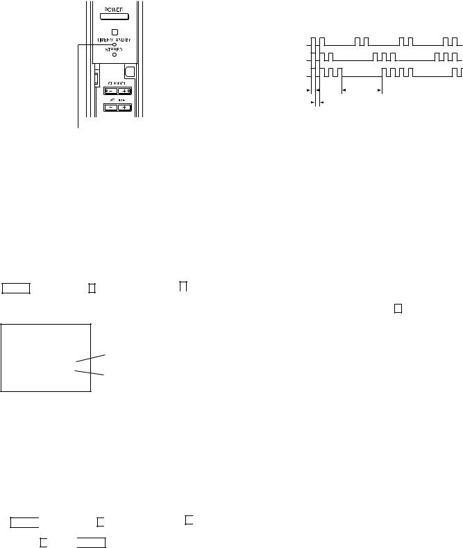
SELF-DIAGNOSTIC FUNCTION |
Self Diagnosis |
Supported model |
The units in this manual contain a self-diagnostic function. If an error occurs, the STANDBY/TIMER LED will automatically begin to fl ash. The number of times the LED fl ashes translates to a probable source of the problem. A defi nition of the STANDBY/TIMER LED fl ash indicators is listed in the instruction manual for the user’s knowledge and reference. If an error symptom cannot be reproduced, the Remote Commander can be used to review the failure occurrence data stored in memory to reveal past problems and how often these problems occur.
Diagnostic Test Indicators
When an error occurs, the STANDBY/TIMER LED will fl ash a set number of times to indicate the possible cause of the problem. If there is more than one error, the LED will identify the fi rst of the problem areas.
Results for all of the following diagnostic items are displayed on screen. If the screen displays a “0”, no error has occurred.
|
No. of times |
|
|
|
|
Diagnostic Item |
STAND BY / |
|
Probable Cause Location |
|
Detected Symptoms |
TIMER |
|
|
|||
|
|
|
|
|
|
|
lamp flashes |
|
|
|
|
Power does not turn on |
Does not light |
• |
Power cord is not plugged in. |
• Power does not come on. |
|
|
|
• |
Fuse is burned out (F6001). (G Board) |
• No power is supplied to the TV. |
|
|
|
|
|
• AC Power supply is faulty. |
|
+B overcurrent (OCP)* |
2 times |
• |
H.OUT (Q8024) is shorted. (D Board) |
• Power does not come on. |
|
|
|
• |
+B PWM (Q8035, Q8038) is shorted. |
• Load on power line shorted. |
|
|
|
|
(D Board) |
|
|
+B overvoltage (OVP) |
3 times |
• |
IC501 is faulty. (G Board) |
• |
Has entered standby mode. |
|
|
• |
IC5002 is faulty. (G Board) |
|
|
Vertical deflection stopped |
4 times |
• |
± 15V is not supplied. (D Board) |
• Has entered standby state after |
|
|
|
• |
IC8003 is faulty. (A Board) |
|
horizontal raster. |
|
|
• Vertical deflection pulse is |
|||
|
|
|
|
||
|
|
|
|
|
stopped. |
|
|
|
|
• Power line is shorted, or |
|
|
|
|
|
|
power supply is stopped. |
White Balance Failure |
5 times |
• |
Video OUT (IC7101, IC7201, IC7301) |
• No raster is generated. |
|
(Not Balanced) |
|
• |
is faulty. (CR, CG, CB Boards) |
• CRT Cathode current detection |
|
|
|
CRT drive (IC309) is faulty. (A Board) |
|
reference pulse output is small. |
|
|
|
• |
Screen (G2) is improperly adjusted. ** |
|
|
Low B OCP/OVP |
6 times |
• |
+5 line is overloaded. (A, B Boards) |
• |
No picture |
(Overcurrent/Overvoltage) *** |
|
• |
+5 line is shorted. (A, B Boards) |
|
|
Horizontal deflection stopped |
7 times |
• |
Q8035, Q8038 is shorted. (D Board) |
|
|
High-voltage error |
8 times |
• |
T8005 is faulty. (D Board) |
|
|
Audio error |
9 times |
• |
± 19V line is shorted. (A, B Boards) |
• |
No sound |
|
|
• |
IC708 is faulty. (A Board) |
|
|
|
|
• |
PS701 or PS702 is opened. |
|
|
|
|
|
(A Board) |
|
|
*If a +B overcurrent is detected, stoppage of the vertical deflection is detected simultaneously. The symptom that is diagnosed first by the microcontroller is displayed on the screen.
**Refer to Screen (G2) Adjustments in Section 2-2 of this manual
***If TIMER or STAND BY indicator blinks six (6) times, unplug the unit and wait 10 minutes before performing the adjustment.
— 7 —
KP-51WS500/57WS500/65WS500
Display of Standby/Timer LED Flash Count
* One blink is not used for self-diagnosis.
< FRONT PANEL >
• EXAMPLE
<Diagnosis Items> <Number of Blinks>
• +B overcurrent |
2 times |
• +B overvoltage |
3 times |
• Vertical deflection stop |
4 times |
Lamp ON : 0.3 seconds |
|
|
|
|
|
|
|
|
|
|
|
|
|
|
|
|
|
Lamp OFF : |
|||
Lamp OFF : 0.3 seconds |
|
|
|
|
|
|
|
|||
|
|
|
|
|
|
|
3.0 seconds |
|||
|
|
|
|
|
|
|
|
|||
TIMER/STAND BY indicator
Release of TIMER STAND BY indicator blinking
The TIMER/STANDBY indicator blinking display is released by turning OFF the power switch on the TV main unit or removing the plug from the power.
Self-Diagnosis Screen Displays
In cases of malfunctions where it is not possible to determine the symptom such as when the power goes off occasionally or when the screen disappears occasionally, there is a screen display on whether the malfunction occurred or not in the past (and whether the detection circuit operated or not) in order to allow confi rmation.
Screen Display Method
Quickly press the remote command button in the following order from the standby state.
_
Display  Channel 5
  Sound Volume*
 Power ON
*Note that this differs from entering the service mode (sound volume + )
SELF DIAGNOSIS
2 |
: +B OCP |
N/A |
3 |
: +B OVP |
N/A |
4 |
: V STOP |
0 |
5 |
: AKB |
1 |
10 : WDT |
24 |
|
Numeral "0" means that no fault was detected.
Numeral "1" means a fault was detected one time or more
Self-Diagnosis Screen Display
The results display is not automatically cleared. In case of repairs and after repairs, check the self-diagnosis screen and be sure to return the results display to “ 0 ”.
If the results display is not returned to “ 0 ” it will not be possible to judge a new malfunction after completing repairs.
Method of Clearing Results Display
1.Power off (Set to the standby mode.)
2.Display 
 Channel 5
 Sound Volume +
 Power ON (Service Mode)
3.Channel 8

 ENTER (Test reset = Factory preset condition)
Method of Ending Self Diagnosis Screen
When ending the self-diagnosis screen completely, turn the power switch OFF on the remote commander or the main unit.
— 8 —
|
KP-51WS500/57WS500/65WS500 |
Self-Diagnosis Function Operation |
|
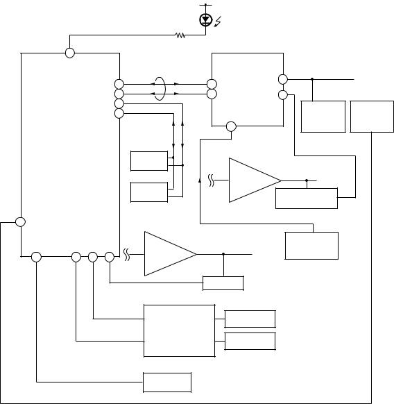
OCP |
Low B and +B line detect DET SHORT, and shut-down POWER ON RELAY. |
|
Reset by turning power on/off. In case of +B is loaded approx. 1.5A or more, microcomputer detects it via IC5005. |
OVP |
In case of +B becomes approx. 150V or more, POWER ON RELAY shuts down and microcomputer detects it via IC5005. |
|
Reset by turning power on/off just the same as OCP. |
Low B |
Occurs when set +5V is out |
V Stop |
In the case of the V Drive disappearing, Q8001 detects it and shuts-down the POWER ON RELAY. The microcomputer detects it and |
|
causes the LED to blink. |
AKB |
IK detection. Makes LED blink when microcomputer doesn’t detect IK, returns of IC309 (CXA2150AQ) 20 seconds or more. |
H Stop |
In case H DRIVE disappears, Q378 detects it and shuts-down POWER ON RELAY. |
|
Microcomputer receives H Stop data from Q378 and makes the LED blink. |
HV Stop |
In case HV becomes 33kV or more, IC8006 detects it and shuts-down POWER ON RELAY. |
|
The microcomputer makes the LED blink. |
Audio |
In case of DC component overlaps the output of Audio Amp., the microcomputer detects it and shuts-down POWER ON RELAY. |
|
The microcomputer makes the LED blink. |
Self-Diagnosis Block Diagram |
D9101 |
|
TIMER/STANDBY |
||
|
R765
49
5. AKB
|
|
|
31 |
|
25 |
IC309 |
34 |
|
|
|
|
|
CXA2150AQ |
6. H STOP |
|
||
|
|
|
28 |
|
26 |
|
||
|
|
|
BUS |
Y/C JUNGLE |
35 |
|
||
|
|
|
29 |
|
Q378 |
|
||
|
|
|
|
|
|
|
||
|
|
|
|
|
|
|
IC8006 |
|
|
|
|
30 |
|
|
|
H PULSE |
|
|
|
|
|
|
|
|
||
|
|
|
|
|
|
|
HV Detector |
|
|
|
|
|
|
|
58 |
Detector |
|
|
|
|
|
|
|
|
||
|
IC704 |
|
|
|
|
|
4. V STOP |
|
|
|
|
|
IC702 |
|
|
|
|
|
MAIN-CPU |
|
|
|
|
|
|
|
|
|
|
|
EEPROM |
|
|
|
|
|
|
|
|
|
|
IC8003 |
|
|
|
|
|
|
IC703 |
|
V Drive |
|
|
|
|
|
|
|
|
Q8001 |
|
|
|
|
|
|
EEPROM |
|
|
|
|
|
|
|
|
|
|
V Pulse Detector |
|
|
|
|
|
|
|
|
|
|
|
53 |
|
|
|
|
5. AKB |
|
|
|
|
|
|
|
|
|
|
|
|
|
|
|
|
IC708 |
|
|
|
|
|
|
|
|
|
|
|
C Board |
|
43 |
44 |
45 |
24 |
Audio AMP |
|
|
|
|
|
|
|
|
|
||||
|
|
|
9. Audio |
DC Detect |
|
|
||
|
|
|
|
|
|
|
||
|
|
3. OVP |
IC5005 |
|
OVP DETECT |
|
|
|
|
|
|
|
|
|
|
||
|
|
|
|
OVP Buffer |
|
|
|
|
|
|
2. OCP |
OCP Buffer |
|
OCP DETECT |
|
|
|
|
|
|
|
|
|
|
||
|
|
|
|
|
|
|
|
|
|
6. LOW B |
|
|
Q714 |
|
|
|
|
|
|
|
|
|
|
|
|
|
|
|
|
|
+5V DETECT |
|
|
|
|
|
8. HV.STOP |
|
|
|
|
|
|
|
|
|
|
|
— 9 — |
|
|
|
|
KP-51WS500/57WS500/65WS500
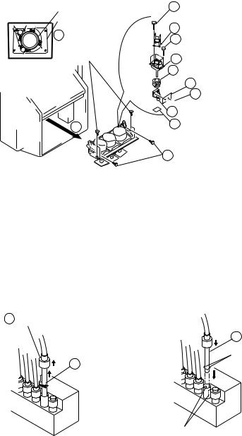
SECTION 1: DISASSEMBLY
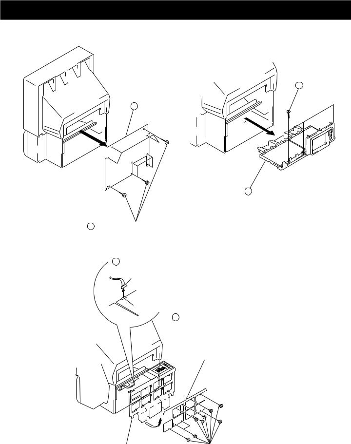
1-1. REAR BOARD REMOVAL |
1-2. CHASSIS ASSEMBLY REMOVAL |
1 Three screws, dome washer
HEX tap 4 x 20
2 Rear board
2 Chassis assy
1Nine Screws, dome washer HEX tap 4 x 20
1-3. SERVICE POSITION
1Disconnect CN17, 18, and 19 on the A board.
From V board CN9001.
(The extension cable is not
|
supplied because of the |
A board |
countermeasure for radiation.) |
CN17, 18, and 19 |
|
D board |
2 Covers |
Remove covers from chassis assembly
with pliers when checking printed circuit boards. After checking, turn the covers over
and re-secure them with the screws.
Chassis assembly |
Screws |
|
(+BVTP 3x12) |
— 10 —
KP-51WS500/57WS500/65WS500
1-4. H2 BOARD REMOVAL
2 Screw, dome washer |
3 Six screws |
|
HEX tap 4x20 |
(+BVTP 4x12 |
|
4 H2 board |
||
|
||
1 Cap, speaker grille |
5 Button, multi |
|
|
||
2 Screw, dome washer |
||
HEX tap 4x20 |
|
|
1 |
Cap, speaker grille |
|
1-5. H1 BOARD REMOVAL
2 Bracket H1
6 Button, power
7 Guide, LED
1-6. H3 BOARD REMOVAL
2 Holder, front teminal |
1 Screws |
|
(+BVTP 4x12)
3 Two screws (+BVTP 3x12)
4 Bracket, H3
7 H3 board


 6 Screw
(+BVTP 3x12)
5 Door, front terminal
1 Two screws (+BVTP 4x12)
4 H1 board
3 Screw
(+BVTP 3x12)
5 Screw
(+BVTP 4x12)
— 11 —

KP-51WS500/57WS500/65WS500
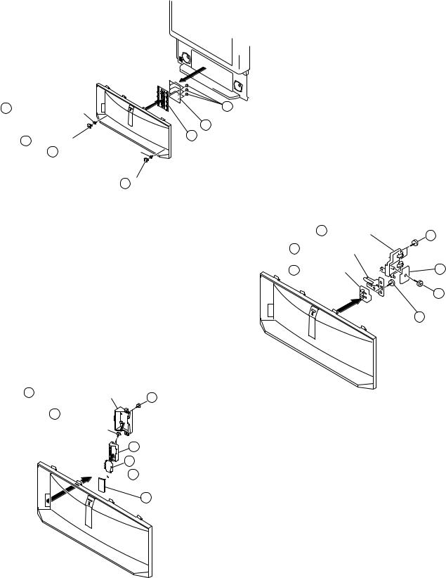
1-7. MIRROR COVER REMOVAL |
1-8. BEZNET ASSEMBLY REMOVAL |
1 Twenty three screws, |
2 Screws, |
dome washer HEX tap 4x20 |
dome washer HEX tap 4x20 |
3 Beznet assy
2 Mirror cover
1 Screws,
dome washer HEX tap 4x20
1-9. S BOARD REMOVAL |
1-10.AD BOARD AND B BOARD REMOVAL |
||
Sensor |
7 S board |
|
|
bracket (B) |
|
1 B board |
|
|
|
||
6 |
|
|
|
|
5 Claws |
1 AD board |
|
Sensor |
3 Two screws |
||
(+BVTP 4x12) |
|||
bracket (A) |
|||
|
|
||
|
|
1 Four screws |
|
|
|
(+BVTP 4x12) |
|
|
2 |
L screen holder |
|
4 |
Two screws |
Main bracket |
|
(+BVTP 4x12)
— 12 —

KP-51WS500/57WS500/65WS500
1-11.G BOARD REMOVAL
|
2 Claws |
3 Bracket G |
|
|
|
2 Claw |
|
2 Claw |
|
1 screw |
|
|
|
(+BVTP 4x12) |
4 Four screws (+BVTP 3x12)
5 G board
Main bracket
1-12.TERMINAL BOARD, A BOARD, D BOARD, U BOARD, AND UD BOARD REMOVAL
3 Two screws (+BVTP 3x12)
6 Screws 5 U board |
4 UD board |
(+BVTP 3x12) |
|
6 Six screws 7 A board (+BVTP 3x12) 
2 Terminal board
1 Five screws
(+BVTP 3x12)
8 D board
1 Two screws
(+BVTP 4x20 dome washer)
5 Claws
Main bracket
— 13 —
KP-51WS500/57WS500/65WS500
1-13.PICTURE TUBE REMOVAL
CAUTION Removing the arrow-marked screws is strictly prohibited.
If removed, it may cause liquid spill.
Lens
Picture tube
2Four screws, dome washer HEX tap 4x20
3
4Four screws,
dome washer HEX tap 4x20
5 Lens
11Four screws (+BVTP 4x12)
12 Picture tube
10 Deflection yoke
9 V board
8 Two screws

 (+BVTP 3x12) 7 Neck assy
6CR board
1 Four screws,
dome washer HEX tap 4x20
1-14.HIGH-VOLTAGE CABLE INSTALLATION AND REMOVAL
(1) Removal |
(2) Installation |
1 Rubber cap |
|
1 HV cable Hook
2 HV cable turn 90°
Gutter
— 14 —

KP-51WS500/57WS500/65WS500
SECTION 2: SET-UP ADJUSTMENTS
2-1. SCREEN VOLTAGE ADJUSTMENT |
2-3. DEFLECTION YOKE TILT ADJUSTMENT |
||||
(COARSE ADJUSTMENT) |
1. Connect the color bar generator monoscope pattern to Video 1 input. |
||||
|
|
|
|||
1. Receive the Monoscope signal.. |
|
2. Cover the red and blue CRT lenses with lens caps to allow only green |
|||
|
to show (or use the method shown in the note below for turning off the |
||||
2. Set BRIGHTNESS to 50% and PICTURE to minimum. |
|||||
CRTs individually without using lens caps). |
|||||
3. Turn the red VR on the focus block all the way to the left and then |
3. Loosen the CRT’s deßection yoke set screw and align the tilt of |
||||
gradually turn it to the right until the retrace line is barely visible. |
the deßection yoke so that the horizontal bars at the center of the |
||||
4. Gradually turn the control to the left until the retrace line disappears. |
monoscope pattern are horizontal. |
||||
|
|
|
4. After aligning the deßection yoke fasten it securely to the |
||
|
|
|
funnel-shaped portion (neck) of the CRT. |
||
R |
G |
B |
The tilt of the deßection yoke is aligned in the mode. |
||
|
|
|
5. Cover the green and blue CRT lenses with lens caps to allow only |
||
|
SCREEN |
|
green to show (or use the method shown in the note below for turning |
||
R |
G |
B |
off the CRTs individually without using lens caps), then repeat steps |
||
|
FOCUS |
|
3 and 4 for the red CRT. |
|
|
|
|
Cover the green and red CRT lenses with lens caps to allow only |
|||
|
|
|
|||
|
FOCUS Block |
green to show (or use the method shown in the note below for turning |
|||
|
off the CRTs individually without using lens caps), then repeat steps |
||||
|
|
|
3 and 4 for the blue CRT. |
|
|
2-2. SCREEN (G2) ADJUSTMENT |
Note: If lens caps are unavailable, you can cut off the unnecessary color |
||||
(FINE ADJUSTMENT) |
beams by controlling the service mode 2150P-2 1 RGBS. |
||||
|
|
||||
|
|
|
|
4-pole magnet |
|
If the jig described below is available, it is recommended that the G2 |
2-pole magnet |
Deflection yoke |
|||
Fine Mode Adjustment be performed to set the screen controls to their |
|
|
|||
optimal condition. If desired, you can build the jig illustrated below, |
|
|
|||
using 3-watt resistors. Please note that if the proper voltage is not |
|
|
|||
obtained with the listed resistor’s values, then increase or decrease one |
|
|
|||
of the values in the resistor network to obtain the correct voltage. |
|
|
|||
1. Select VIDEO-1 mode no signal applied (the screen must be black). |
Centering magnet |
||||
2. Connect the G2 JIG. |
|
|
|
Anode cap |
|
3.SW on JIG.
4.Connect an oscilloscope to the TP7101(KR), TP7202(KG) and TP7301(KB) of CR board, CG board, and CB board.
5.Adjust red, green, and blue screen voltage to 177.5+/-0.5V with screen VR on the focus block.
|
|
|
K |
G2 JIG |
|
SW |
|
|
|
|
|
TO CG BOARD |
3.3k |
3.9k |
5.6k 6.8k |
TP7202 |
|
|
GND |
(210V) |
|
|
All resistors are 3W type |
|
|
|
|
|
177.5V +/- 0.5V |
pedestal level |
|
GND |
|
|
|
— 15 —

2-4. FOCUS LENS ADJUSTMENT
In this adjustment, use the remote commander while in service mode. For details on the usage of the service mode and the remote commander, please refer to section
2-10. ELECTRICAL ADJUSTMENTS BY REMOTE COMMANDER.
1.Loosen the lens screw.
2.Cover the red and blue CRT lenses with lens caps to allow only green to show (or use the method shown in the note below for turning off the CRTs individually without using lens caps).
3.Turn the green lens to adjust to the optimum focus point with the crosshatch signal.
4.Tighten the lens screw.
5.Cover the green and blue CRT lenses with the lens caps to allow only red to show (or use the method shown in the note below for turning off the CRTs individually without using lens caps).
6.Turn the red lens to adjust to the optimum focus point with the crosshatch signal.
7.Tighten the lens screw.
8.Cover the green and red CRT lenses with the lens caps to allow only blue to show (or use the method shown in the note below for turning off the CRTs individually without using lens caps).
9.Turn the blue lens to adjust to the optimum focus point with the crosshatch signal.
10.Tighten the lens screw.
11.After adjusting the items:
2-5. FOCUS VR ADJUSTMENT,
2-6. 2-POLE MAGNET ADJUSTMENT,
2-8. 4-POLE MAGNET ADJUSTMENT,
reconÞrm the optimum focus point and adjust again if necessary.
* Every time 6 is pressed, the test signal changes to: “crosshatch+video signal” → “crosshatch+borderline(black)” → ”crosshatch(black)” → “dots(black)” → off
Test Signal
Note: If lens caps are unavailable, you can cut off the unnecessary color beams by controlling the service mode 2150P-2 1 RGBS.
KP-51WS500/57WS500/65WS500
2-5. FOCUS VR ADJUSTMENT
1.Set generator to crosshatch.
2.Cover the red and blue CRT lenses with lens caps to allow only green to show (or use the method shown in the note below for turning off the CRTs individually without using lens caps).
3.Turn the green focus VR on the focus block to adjust to the optimum focus point with the crosshatch signal.
4.Cover the green and blue picture lenses with lens caps to allow only red to show (or use the method shown in the note below for turning off the CRTs individually without using lens caps).
5.Turn the red focus VR on the focus block to adjust to the optimum focus point with the crosshatch signal.
6.Cover the green and red picture lenses with lens caps to allow only blue to show (or use the method shown in the note below for turning off the CRTs individually without using lens caps).
7.Turn the blue focus VR on the focus block to adjust to the optimum focus point with the crosshatch signal.
8.After adjusting the items:
2-4. FOCUS LENS ADJUSTMENT,
2-6. 2-POLE MAGNET ADJUSTMENT,
2-8. 4-POLE MAGNET ADJUSTMENT,
reconÞrm the optimum focus point and adjust again if necessary.
Note: If lens caps are unavailable, you can cut off the unnecessary color beams by controlling the service mode 2150P-2 1 RGBS.
Scanning line visible.
A
 Minimize both A and B.
Lens |
B |
Center of crosshatch |
— 16 —
Loading...