


 Loading...
HD CAMCORDER
HDW-790 HDW-790P
OPERATION MANUAL [English] 1st Edition

WARNING
To reduce the risk of fire or electric shock, do not expose this apparatus to rain or moisture.
To avoid electrical shock, do not open the cabinet. Refer servicing to qualified personnel only.
For the customers in the U.S.A.
This equipment has been tested and found to comply with the limits for a Class B digital device, pursuant to Part 15 of the FCC Rules. These limits are designed to provide reasonable protection against harmful interference in a residential installation. This equipment generates, uses, and can radiate radio frequency energy and, if not installed and used in accordance with the instructions, may cause harmful interference to radio communications. However, there is no guarantee that interference will not occur in a particular installation. If this equipment does cause harmful interference to radio or television reception, which can be determined by turning the equipment off and on, the user is encouraged to try to correct the interference by one or more of the following measures:
—Reorient or relocate the receiving antenna.
—Increase the separation between the equipment and receiver.
—Connect the equipment into an outlet on a circuit different from that to which the receiver is connected.
—Consult the dealer or an experienced radio/TV technician for help.
You are cautioned that any changes or modifications not expressly approved in this manual could void your authority to operate this equipment.
All interface cables used to connect peripherals must be shielded in order to comply with the limits for a digital device pursuant to Subpart B of Part 15 of FCC Rules.
For the State of California, USA only
Perchlorate Material - special handling may apply, See www.dtsc.ca.gov/hazardouswaste/perchlorate Perchlorate Material : Lithium battery contains perchlorate.
For the customers in Europe
This product with the CE marking complies with the EMC Directive issued by the Commission of the European Community.
Compliance with this directive implies conformity to the following European standards:
•EN55103-1 : Electromagnetic Interference (Emission)
•EN55103-2 : Electromagnetic Susceptibility (Immunity) This product is intended for use in the following Electromagnetic Environments: E1 (residential), E2 (commercial and light industrial), E3 (urban outdoors), E4 (controlled EMC environment, ex. TV studio).
For the customers in Europe
The manufacturer of this product is Sony Corporation, 1-7-1 Konan, Minato-ku, Tokyo,Japan.
The Authorized Representative for EMC and product safety is Sony Deutschland GmbH,Hedelfinger Strasse 61, 70327 Stuttgart, Germany. For any service or guarantee matters please refer to the addresses given in separate service or guarantee documents.
For the customers in the USA and Canada RECYCLING LITHIUM-ION BATTERIES
Lithium-Ion batteries are recyclable.
You can help preserve our environment by returning your used rechargeable batteries to the collection and recycling location nearest you.
For more information regarding recycling of rechargeable batteries, call toll free 1-800-822-8837, or visit http://www.rbrc.org/
Caution: Do not handle damaged or leaking Lithium-Ion batteries.
Voor de Klanten in Nederland
•Gooi de batterij niet weg maar lever deze in als klein chemisch afval (KCA).
•Dit apparaat bevat een vast ingebouwde batterij die niet vervangen hoeft te worden tijdens de levensduur van het apparaat.
•Raadpleeg uw leverancier indien de batterij toch vervangen moet worden. De batterij mag alleen vervangen worden door vakbekwaam servicepersoneel.
•Lever het apparaat aan het einde van de levensduur in voor recycling, de batterij zal dan op correcte wijze verwerkt worden.
For the customers in Taiwan only
2

AVERTISSEMENT
Afin de réduire les risques d’incendie ou d’électrocution, ne pas exposer cet appareil à la pluie ou à l’humidité.
Afin d’écarter tout risque d’électrocution, garder le coffret fermé. Ne confier l’entretien de l’appareil qu’à un personnel qualifié.
Pour les clients européens
Ce produit portant la marque CE est conforme à la Directive sur la compatibilité électromagnétique (EMC) émise par la Commission de la Communauté européenne.
La conformité à cette directive implique la conformité aux normes européennes suivantes :
•EN55103-1 : Interférences électromagnétiques (émission)
•EN55103-2 : Sensibilité électromagnétique (immunité)
Ce produit est prévu pour être utilisé dans les environnements électromagnétiques suivants : E1 (résidentiel), E2 (commercial et industrie légère), E3 (urbain extérieur) et E4 (environnement EMC contrôlé, ex. studio de télévision).
Pour les clients en Europe
Le fabricant de ce produit est Sony Corporation, 1-7-1 Konan, Minato-ku, Tokyo, Japon.
Le représentant autorisé pour EMC et la sécurité des produits est Sony Deutschland GmbH, Hedelfinger Strasse 61, 70327 Stuttgart, Allemagne. Pour toute question concernant le service ou la garantie, veuillez consulter les adresses indiquées dans les documents de service ou de garantie séparés.
Pour les utilisateurs aux Etats-Unis et au Canada. RECYCLAGE DES ACCUMULATEURS AUX IONS DE LITHIUM
Les accumulateurs aux ions de lithium sont recyclables. Vous pouvez contribuer à préserver l’environnement en rapportant les piles usées dans un point de collection et recyclage le plus proche.
Pour plus d’informations sur le recyclage des accumulateurs, téléphonez le numéro gratuit 1-800-822-8837 (Etats-Unis et Canada uniquement), ou visitez http://www.rbrc.org/ Avertissment: Ne pas utiliser des accumulateurs aux ions de lithium qui sont endommagées ou qui fuient.
WARNUNG
Um die Gefahr von Bränden oder elektrischen Schlägen zu verringern, darf dieses Gerät nicht Regen oder Feuchtigkeit ausgesetzt werden.
Um einen elektrischen Schlag zu vermeiden, darf das Gehäuse nicht geöffnet werden. Überlassen Sie Wartungsarbeiten stets nur qualifiziertem Fachpersonal.
Für Kunden in Europa
Dieses Produkt besitzt die CE-Kennzeichnung und erfüllt die EMV-Richtlinie der EG-Kommission.
Angewandte Normen:
•EN55103-1: Elektromagnetische Verträglichkeit (Störaussendung)
•EN55103-2: Elektromagnetische Verträglichkeit (Störfestigkeit),
für die folgenden elektromagnetischen Umgebungen: E1 (Wohnbereich), E2 (kommerzieller und in beschränktem Maße industrieller Bereich), E3 (Stadtbereich im Freien) und E4 (kontrollierter EMV-Bereich, z.B. Fernsehstudio).
Für Kunden in Europa
Der Hersteller dieses Produkts ist Sony Corporation, 1-7-1 Konan, Minato-ku, Tokyo, Japan.
Der autorisierte Repräsentant für EMV und Produktsicherheit ist Sony Deutschland GmbH, Hedelfinger Strasse 61, 70327 Stuttgart, Deutschland. Bei jeglichen Angelegenheiten in Bezug auf Kundendienst oder Garantie wenden Sie sich bitte an die in den separaten Kundendienstoder Garantiedokumenten aufgeführten Anschriften.
Für Kunden in Deutschland
Entsorgungshinweis: Bitte werfen Sie nur entladene Batterien in die Sammelboxen beim Handel oder den Kommunen. Entladen sind Batterien in der Regel dann, wenn das Gerät abschaltet und signalisiert „Batterie leer“ oder nach längerer Gebrauchsdauer der Batterien „nicht mehr einwandfrei funktioniert“. Um sicherzugehen, kleben Sie die Batteriepole z.B. mit einem Klebestreifen ab oder geben Sie die Batterien einzeln in einen Plastikbeutel.
3

Table of Contents
Setting the Frame Frequency ............................................... |
9 |
Chapter 1 Overview
1-1 |
Features ......................................................................... |
11 |
|
|
1-1-1 |
Camera Features ............................................................. |
11 |
|
1-1-2 |
VTR Features.................................................................. |
12 |
|
1-1-3 |
Other Features................................................................. |
12 |
1-2 |
Example of System Configuration .............................. |
14 |
|
1-3 |
Precautions ................................................................... |
15 |
|
Chapter 2 Locations and Functions of Parts and Controls
2-1 Power Supply ................................................................ |
16 |
|
2-2 Accessory Attachments ............................................... |
17 |
|
2-3 Audio Functions............................................................ |
18 |
|
2-4 Shooting and Recording/Playback Functions ........... |
21 |
|
2-5 Menu Operating Section............................................... |
26 |
|
2-6 |
Time Code System........................................................ |
28 |
2-7 |
Warnings and Indications ............................................ |
30 |
2-8 |
Warnings and Indications on the Display Panel ........ |
31 |
2-9 |
Indicators in the Viewfinder ......................................... |
33 |
Chapter 3 Recording and Playback
3-1 About Cassettes............................................................ |
34 |
|
3-1-1 Loading and Unloading a Cassette ................................. |
34 |
|
3-1-2 |
Preventing Accidental Erasure........................................ |
35 |
3-2 Recording ...................................................................... |
36 |
|
3-2-1 |
Basic Procedures............................................................. |
36 |
3-2-2 Continuous Recording .................................................... |
37 |
|
3-2-3 Recording Good Shot Marks .......................................... |
38 |
|
3-2-4 Recording a Recording Start Mark ................................. |
39 |
|
3-2-5 |
Starting a Shoot with a Few Seconds of Pre-Stored Picture |
|
|
Data (Picture Cache Function: with the HKDW-703).... |
40 |
3-2-6 |
Shooting Picture at Intervals (Interval Rec Function: with |
|
|
the HKDW-703) ............................................................. |
42 |
3-2-7 Continuous Recording on Previous Cut.......................... |
49 |
|
4 |
Table of Contents |
|
|

3-2-8 Searching for the Last Recorded Portion and Turning on |
|
Recording Pause Mode (End Search Function) .............. |
50 |
3-3 Checking Recording and Playback.............................. |
50 |
3-3-1 Checking the Last Two Seconds of the Recording — |
|
Recording Review........................................................... |
50 |
3-3-2 Checking the Recording on the Color Video Monitor — |
|
Playback in Color............................................................ |
51 |
3-3-3 Checking the Camera Picture on the Viewfinder and/or |
|
Color Video Monitor....................................................... |
51 |
3-4 Recording the Recording Start Time Code onto the |
|
Memory Label — Tele-File ............................................ |
52 |
3-4-1 Recording the Recording Start Time Code onto the |
|
Memory Label................................................................. |
52 |
3-4-2 Recording a Tele-File Mark (OK/NG/KP) onto the |
|
Memory Label................................................................. |
52 |
3-4-3 Warning/Error Messages in Memory Label Operation... |
54 |
3-4-4 Confirming the Remaining Capacity on the Memory |
|
Label .............................................................................. |
55 |
3-4-5 Clearing Recorded Data .................................................. |
55 |
3-5 Freezing a Picture During Playback............................. |
56 |
3-6 Setting the Stand-by off Timer During Rec-Pause ..... |
57 |
Chapter 4 Adjustments and Settings for Recording
4-1 Adjusting the Black Balance and the White Balance .58
|
4-1-1 |
Adjusting the Black Balance........................................... |
58 |
|
4-1-2 |
Adjusting the White Balance .......................................... |
59 |
4-2 |
Setting the Electronic Shutter ...................................... |
61 |
|
|
4-2-1 |
Shutter Modes ................................................................. |
61 |
|
4-2-2 |
Selecting the Shutter Mode and Shutter Speed............... |
62 |
4-3 |
Changing the Reference Value for Automatic Iris |
|
|
|
Adjustment..................................................................... |
65 |
|
4-4 |
Adjusting the Audio Level ............................................ |
67 |
|
|
4-4-1 Manually Adjusting the Audio Input Level of the AUDIO |
||
|
|
IN CH-1/CH-2 Connectors ............................................. |
67 |
|
4-4-2 |
Manually Adjusting the Audio Level of the Front |
|
|
|
Microphone ..................................................................... |
68 |
|
4-4-3 Input Level of Audio Channels CH-3 and CH-4 ............ |
69 |
|
4-5 |
Setting the Time Data .................................................... |
70 |
|
|
4-5-1 |
Setting the Time Code..................................................... |
70 |
|
4-5-2 Saving the Actual Time in the Time Code...................... |
71 |
|
|
4-5-3 |
Setting the User Bits........................................................ |
71 |
|
4-5-4 Synchronizing the Time Code......................................... |
72 |
|
Table of Contents |
5 |
|
|

Chapter 5 Menu Displays and Detailed Settings
5-1 Menu Organization and Operation .............................. |
74 |
|
5-1-1 Menu Organization ......................................................... |
74 |
|
5-1-2 Basic Menu Operations................................................... |
75 |
|
5-1-3 Editing the USER Menu ................................................. |
77 |
|
5-1-4 |
Adding Functions to be Assigned to Assignable |
|
|
Switches.......................................................................... |
79 |
5-2 Status Display on the Viewfinder Screen ................... |
81 |
|
5-2-1 |
Layout of the Status Display on the Viewfinder Screen.81 |
|
5-2-2 |
Selecting Display Items .................................................. |
83 |
5-2-3 Display Modes and Setting Change Confirmation/ |
|
|
|
Adjustment Progress Messages ...................................... |
84 |
5-2-4 |
Selecting the Items for Which the ‘!’ LED is to Light ... |
85 |
5-2-5 |
Setting Marker Display................................................... |
86 |
5-2-6 |
Setting the Viewfinder .................................................... |
87 |
5-2-7 Recording Shot Data Superimposed on the Color Bars..87 |
||
5-2-8 |
Setting the Shot ID.......................................................... |
88 |
5-2-9 |
Displaying the Status Confirmation Windows ............... |
90 |
5-2-10 |
Confirming the Image of the Return Video Signal in the |
|
|
Viewfinder ...................................................................... |
91 |
5-3 Adjustments and Settings from Menus ...................... |
92 |
|
5-3-1 |
Setting Gain Values for the GAIN Selector Positions.... |
92 |
5-3-2 |
Selecting Output Signals................................................. |
93 |
5-3-3 |
Setting the Color Temperature Manually ....................... |
94 |
5-3-4 |
Specifying an Offset for the Auto White Balance |
|
|
Setting............................................................................. |
94 |
5-3-5 |
Assigning Functions to Assignable Switches ................. |
95 |
5-3-6 |
Setting the Date/Time of the Internal Clock................... |
97 |
5-3-7 |
Selecting a Lens File....................................................... |
98 |
5-3-8 Using AMID Data........................................................... |
99 |
|
5-3-9 Using the Hyper Gamma .............................................. |
101 |
|
5-3-10 Using the Freeze Mix Function .................................. |
102 |
|
5-4 Resetting USER Menu Settings to the Standard |
|
|
Settings........................................................................ |
105 |
|
Chapter 6 Saving and Loading User Setting Data
6-1 Saving and Loading User Files.................................. |
107 |
|
6-1-1 |
Handling the “Memory Stick” ...................................... |
107 |
6-1-2 |
Saving USER Menu Data (User File) to the “Memory |
|
|
Stick” ............................................................................ |
108 |
6-1-3 |
Loading Saved Data from a “Memory Stick”............... |
110 |
6 |
Table of Contents |
|
|

6-2 |
Saving and Loading Scene Files................................ |
111 |
|
|
6-2-1 |
Saving a Scene File ....................................................... |
111 |
|
6-2-2 |
Loading a Scene File..................................................... |
113 |
|
6-2-3 |
Resetting the Camcorder Settings to the Standard Settings |
|
|
|
Saved in the Reference File .......................................... |
114 |
6-3 |
Jumping to a File-Related Menu Page When Inserting a |
||
|
“Memory Stick”............................................................ |
115 |
|
Chapter 7 Setting Up the Camcorder
7-1 Power Supply ............................................................... |
117 |
|
7-1-1 |
Using a Battery Pack..................................................... |
117 |
7-1-2 |
Avoiding Breaks in Operation Due to an Exhausted |
|
|
Battery........................................................................... |
117 |
7-1-3 Using an AC Adaptor.................................................... |
118 |
|
7-1-4 |
Using the Anton Bauer Ultralight System .................... |
118 |
7-2 Adjusting the Viewfinder............................................. |
118 |
|
7-2-1 |
Adjusting the Viewfinder Position................................ |
118 |
7-2-2 |
Adjusting the Viewfinder Focus and Screen................. |
119 |
7-2-3 |
Detaching the Viewfinder ............................................. |
119 |
7-2-4 |
Detaching the Eyepiece................................................. |
120 |
7-3 Mounting the Lens....................................................... |
121 |
|
7-4 Adjusting the Flange Focal Length............................ |
121 |
|
7-5 Audio Input System ..................................................... |
122 |
|
7-5-1 |
Using the Supplied Microphone.................................... |
122 |
7-5-2 |
Using an External Microphone ..................................... |
123 |
7-5-3 |
Attaching a UHF Portable Tuner (for a UHF Wireless |
|
|
Microphone System)..................................................... |
125 |
7-5-4 Connecting Line Input Audio Equipment..................... |
126 |
|
7-6 Tripod Mounting .......................................................... |
126 |
|
7-7 Attaching/Detaching the Shoulder Strap................... |
127 |
|
7-8 Adjusting the Shoulder Pad Position ........................ |
128 |
|
7-9 Attaching the Rain Cover (Not Supplied) .................. |
128 |
|
7-10 Connecting the Remote Control Unit....................... |
129 |
|
Chapter 8 Maintenance
8-1 |
Testing the Camcorder Before Shooting................... |
131 |
|
|
8-1-1 |
Preparations for Testing ................................................ |
131 |
|
8-1-2 |
Testing the Camera ....................................................... |
131 |
|
8-1-3 |
Testing the VTR............................................................ |
133 |
8-2 |
Maintenance ................................................................. |
135 |
|
Table of Contents |
7 |
|
|

|
8-2-1 Cleaning the Video Heads ............................................ |
135 |
|
|
8-2-2 |
Cleaning the Viewfinder............................................... |
135 |
|
8-2-3 Cleaning the Tape Transport System............................ |
135 |
|
|
8-2-4 |
Performing Maintenance After Use Under Severe |
|
|
|
Condition ...................................................................... |
135 |
8-3 |
Periodic Inspection..................................................... |
136 |
|
|
8-3-1 |
Hours Meter .................................................................. |
136 |
|
8-3-2 |
List of Parts for the Periodic Inspection ....................... |
136 |
8-4 |
Operation Warnings.................................................... |
138 |
|
Appendixes
Specifications..................................................................... |
140 |
General .................................................................................... |
140 |
Video Camera Section............................................................. |
140 |
VTR Section ............................................................................ |
141 |
Recommended Additional Equipment .................................... |
141 |
Menu List ............................................................................ |
143 |
OPERATION Menu ................................................................ |
143 |
PAINT Menu ........................................................................... |
150 |
MAINTENANCE Menu ......................................................... |
155 |
FILE Menu .............................................................................. |
164 |
DIAGNOSIS Menu ................................................................. |
167 |
About a “Memory Stick”.................................................... |
168 |
Index.................................................................................... |
170 |
8 |
Table of Contents |
|
|

Setting the Frame
Frequency
The factory setting of the frame frequency of the HDW790 is 59.94i. On the HDW-790P, the frame frequency is factory-set to 50i. To use the camcorder with a format other than the one set at the factory, you should change the setting of the frame frequency first.
|
Switch cover |
MENU knob |
MENU ON/OFF switch |
|
POWER switch |
Note
In the procedure below, the HDW-790 is used for illustration purposes.
1 Set the POWER switch to ON.
2 Open the switch cover, and then set the MENU ON/ OFF switch to ON while pushing the MENU knob.
The TOP menu appears.
3 Turn the MENU knob to move the b mark to MAINTENANCE, then push the MENU knob.
When the MAINTENANCE menu is used for the first time, the CONTENTS page appears.
When a question mark 


 appears at the top left of the
title page, you can switch pages by turning the MENU knob
Or, if you have used the MAINTENANCE menu before, the page that was on the screen when the last menu operation ended appears.
4 When the CONTENTS page is displayed, push the MENU knob once, and then turn the MENU knob to move the b mark to FORMAT.
Or, turn the MENU knob until the FORMAT page appears from the CONTENTS page.
When any page of the MAINTENANCE menu is displayed, turn the MENU knob until the FORMAT page appears.
5 Push the MENU knob.
The FORMAT page appears.
Frame frequency currently selected
6 Confirm the b mark is positioned at NEXT, then push the MENU knob.
The b mark to the left of NEXT changes to a z mark, and the z mark to the left of the setting changes to a ? mark.
Setting the Frame Frequency |
9 |
|
|

7 Turn the MENU knob clockwise or counterclockwise until the desired frame frequency appears.
The message “PLEASE POWER OFF b ON TO CHANGE FORMAT” appears.
8 Set the POWER switch to OFF once, and then to ON.
The camcorder will operate at the desired frame frequency.
Even if you do not push the MENU knob to execute the change, the frame frequency selected in step 7 becomes effective only by turning the power of the camcorder off and on again.
10 |
Setting the Frame Frequency |
|
|
Overview
1-1 Features
The HDW-790/790P camcorder is a color video camera with 1920 (H) × 1080 (V) effective picture elements; it incorporates 2/3-inch CCDs with 2,000,000 picture elements and an HDCAM format recorder combined integrally. The introduction of new integrated circuit technology (LSI) for processing the HD digital signal improves the image quality even further, and simplifies setup (initialization) operations.
Note
In this manual, the HDW-790 is used for illustration purposes.
1-1-1 Camera Features
2/3-inch Power HAD1) CCDs
The high sensitivity, low smear 2/3-inch Power HAD CCDs (FIT-type CCDs) provide high image quality, which puts this HD camcorder at the top of its class.
The HDW-790 is compatible with the 59.94i and 50i formats. And the HDW-790P is compatible with the 50i and 25PsF formats.
1)Abbreviation of “Power Hole-Accumulated Diode.” “Power HAD” is a registered trademark of Sony Corporation.
Camera signal processing for high quality video
•The 12-bit A/D converter provides stable, high-quality images and reliability.
•Blur-free shooting is ensured by a built-in, high
performance electronic shutter that provides a variety of modes, such as ECS1) mode which reduces flickering on the monitor screen, and S-EVS2) mode that improves vertical resolution.
1)ECS: Extended Clear Scan
2)S-EVS: Super Enhanced Vertical Definition System
Chapter 1
Shooting functions to cope with different shooting conditions
•With the scene file function, you can easily recall sets of adjustment values from the built-in memory, to match particular lighting conditions.
•The ATW1) function provides automatic white balance adjustment in response to changing lighting conditions.
•The TruEye™2) process yields distortion-free video, even with high intensity colors.
•The TURBO GAIN button enables an instantaneous boost of the video gain to the maximum 42 dB.
1)ATW: Auto Tracing White balance
2)TruEye: “TruEye” is a trademark of Sony Corporation.
Wide range of menu settings
The menus provide a wide variety of operations and settings, including:
•Status display, message, and marker display settings
•Camera adjustment settings
•Assignable switch function assignment
•“Memory Stick1)” operations
You can assign any settings to a USER menu, to create customized menus.
1) “Memory Stick” is a registered trademark of Sony Corporation.
Saving and recalling settings from a “Memory Stick”
Using an optional “Memory Stick,” you can save menu settings for particular shooting conditions, for recall as required.
Down converter function
•Attaching an optional HKDW-702 extension board (converting to a 525/59.94i and 625/50i signal) allows you to monitor the camera image and playback image in 1080/59.94i, 1080/50i, and 1080/25PsF formats on an NTSC/PAL monitor.
•The HKDW-702 extension board makes it possible to output an SDI signal (corresponding to Embedded Audio).
•Three down-conversion modes are available: SQEZE, LETTR BOX and CROP.
Overview 1 Chapter
Features 11

Overview 1 Chapter
Slow shutter mode function
Installing an optional HKDW-905R extension board enables the camcorder to store up to 64 frames. The slow shutter function is useful not only for shooting in extremely dark conditions without noise, but also for shooting moving objects with a special afterimage effect.
Image inversion function
Installing an optional HKDW-905R extension board, which has an anti-image inversion function, allows you to cancel the image inversion phenomena that occurs when a cine-lens converter is used.
Note
The slow shutter and image inversion functions of the optional HKDW-905R extension board cannot be used at the same time.
ARIB color bar output
When the HKDW-905R Slow Shutter and Image Inverter Board is installed and when the OUTPUT/DCC switch is set to BARS, ARIB multi-format color bar signal is output.
Remote control connectors
By connecting an optional RM-B150/B750 or similar remote control unit, you can control the camera settings of the camcorder externally.
1-1-2 VTR Features
HDCAM format
•Use of the HDCAM format allows high performance HD digital recording and playback while preserving the same ease of use as conventional camcorder equipment.
•The same cassette size (S size) as Digital Betacam can be used to achieve the following long recording times. For 30 frames (59.94i): Approximately 40 minutes
For 25 frames (50i and 25PsF): Approximately 48 minutes
Time Code operations
•LTC1) and VITC2) recording and LTC playback are available.
•The built-in time code generator can be synchronized with an external generator.
•A lithium battery provides the back-up power supply for the built-in time code generator enabling the camcorder to hold the time code for approximately 5 years without supplying the power to the camcorder.
•The time code can be displayed in the LCD window screen even when the power is off. The automatic power
shut-off function allows you to set the time to be displayed from among three patterns.
1)LTC: Longitudinal Time Code
2)VITC: Vertical Interval Time Code
Picture cache recording/interval recording function
Installing an optional HKDW-703 extension board allows the camcorder to constantly store a few seconds (up to 8 seconds) of the most current picture and sound data in the board’s memory. As a result, when you press the VTR START button, the recording starts with the data stored a few seconds before. Installing an optional HKDW-703 extension board enables the camcorder to record pictures intermittently.
Other VTR functions
•Recording continuity from the very next frame is ensured.
•You can automatically rewind and review the last 2 seconds of the recording on the tape for a quick check immediately after shooting.
•A four-times-normal speed color search function provides quick positioning of the tape.
•With the RE-TAKE function, the camcorder searches for the most recently recorded cut and records the new cut over it.
•With the End-Search function, the camcorder searches for the point most recently recorded on the tape and automatically switches to recording pause mode (REC pause).
•The freeze function is provided to obtain a freeze-frame picture from the playback picture on the VTR by pressing the STOP button during playback.
•The camcorder is compatible with the Tele-File1) Memory Label system. When you press the RET button on the lens while recording, the time code valid when you pressed the button is recorded on an optional MLB- 1M-100 memory label attached to the cassette. This is very helpful for management of cassette tapes and to improve the efficiency of tape editing.
1)Tele-File: The Tele-File system is a non-contact data reading/writing system that allows data about recorded material to be stored on a tape label with a non-contact IC memory.
1-1-3 Other Features
HD-SDI output connectors
Two HD-SDI (Embedded Audio) output connectors allow you to monitor camera and playback images without attaching a camera adaptor.
12 Features

Audio functions
•The MIC IN (microphone input) connector (XLR type, 5-pin, female) allows you to connect the supplied stereo microphone. You can record either stereo or monaural sound.
•An optional slot-in UHF portable tuner, WRR-855A/ 855B, can be attached.
•The two AUDIO IN connectors (XLR type, 3-pin) on the rear panel can be switched to line input, microphone input, or + 48V external power, and also to AES/EBU digital audio inputs.
•Four channels of 20-bit digital audio can be recorded.
•The AUDIO OUT connector (XLR 5-pin) allows the camcorder to output signals as stereo audio.
Proper balancing design
The camcorder features a new shoulder-pad system that enables you to adjust the front-to-rear direction position (to ensure proper balance) without the use of any tools.
Freeze Mix function
Apart from the freeze function to obtain a freeze-frame picture from the playback picture on the VTR, a freezeframe picture of the video signal input from the camera can be obtained. The obitained freeze-frame picture and the video from the camera can then be mixed and displayed. This function is available only when the HKDW-905R Slow Shutter and Image Inverter Board is installed.
Function extension interface and optional boards
An extension connector can be attached to the battery attachment on the rear panel.
Use of the following optional boards permits you to expand the existing functions.
•HKDW-702 Down Converter Board
•HKDW-703 Picture Cache Board
•HKDW-905R Slow Shutter and Image Inverter Board
Overview 1 Chapter
Features 13

Overview 1 Chapter
1-2 Example of System Configuration
The diagram below shows a typical configuration of the |
For more information about the fittings, connections, or |
camcorder for ENG and EFP. |
use of additional equipment and accessories, see “Chapter |
In this manual, an optional HDVF-20A HD Electronic |
7 Setting Up the Camcorder” as well as the operation |
Viewfinder is used to instruct how to operate the unit. |
manuals for the connected equipment. |
Viewfinder-related equipment
Name / Purpose |
Magnification |
Part No. |
Fog-proof filter |
— |
1-547-341-11 |
|
|
|
Lens assembly |
–2.8 D to +2.0 D |
A-8262-537-A |
|
|
|
Lens assembly |
–3.6 D to –0.8 D |
A-8262-538-A |
|
|
|
Lens assembly |
–3.6 D to +0.4 D |
A-8267-737-A |
|
|
|
Lens assembly |
–2.4 D to +0.5 D |
A-8314-798-A |
(3 × magnification) |
|
|
|
|
|
BKW-401 Viewfinder Rotation Bracket
Viewfinder
HDVF-20A HD Electronic Viewfinder
HDVF-C30W HD Electronic Viewfinder
Audio input signals
External microphone ECM-674/678 or similar microphone
CAC-12 Microphone Holder
Analog audio equipment
CCXA-53 audio cable
WRR-861A/861B/862A/862B UHF Portable Tuner
WRR-855A/855B UHF Synthesized Tuner Unit
Control signals
RM-B150/B750 Remote Control Unit
“Memory Stick” (see page 142)
AC power supply
Product |
Model name |
AC Adaptor |
AC-DN10 |
|
|
Battery |
|
|
|
Product |
Model name |
Battery Charger |
BC-L70/M150 |
|
|
Battery Pack |
BP-GL65/GL95/L60S |
|
|
Extension board
Product |
Model name |
Down Converter Board |
HKDW-702 |
|
|
Picture Cache Board |
HKDW-703 |
|
|
Slow Shutter and |
HKDW-905R |
Image Inverter Board |
|
|
|
Video output
Video monitor for color image check during shooting
Audio output
Audio equipment for monitoring (XLR 5-pin connector)
14 |
Example of System Configuration |
|
|

1-3 Precautions
Use and Storage
Do not subject the unit to severe shocks
The internal mechanism may be damaged or the body warped.
After use
Always turn off the power.
Before storing the unit for a long period
Remove the battery pack.
Use and storage locations
Store in a level, ventilated place. Avoid using or storing the unit in the following places:
•Places subject to temperature extremes
•Very damp places
•Places subject to severe vibration
•Near strong magnetic fields
•In direct sunlight or close to heaters for extended periods
To prevent electromagnetic interference from portable communications devices
The use of portable telephones and other communications devices near this unit can result in malfunctions and interference with audio and video signals.
It is recommended that the portable communications devices near this unit be powered off.
Note on laser beams
Laser beams may damage the CCDs. If you shoot a scene that includes a laser beam, be careful not to let the laser beam be directed into the lens of the camera.
Phenomena specific to CCD image sensors
The following phenomena that may appear in images are specific to CCD (Charge Coupled Device) image sensors. They do not indicate malfunctions.
White flecks
Although the CCD image sensors are produced with highprecision technologies, fine white flecks may be generated on the screen in rare cases, caused by cosmic rays, etc.
This is related to the principle of CCD image sensors and is not a malfunction.
The white flecks especially tend to be seen in the following cases:
• when operating at a high environmental temperature
•when you have raised the master gain (sensitivity)
•when operating in Slow-Shutter mode
This product has a compensation function and the problem may be alleviated by automatic black balance adjustment
(see page 58).
Vertical smear
When an extremely bright object, such as a strong spotlight or flashlight, is being shot, vertical tails may be produced on the screen, or the image may be distorted.
Monitor screen
Aliasing
Vertical tails shown on the image.
Bright object (e.g. strong  spotlight, strong reflected
light, flashlight, the sun)
When fine patterns, stripes, or lines are shot, they may appear jagged or flicker.
Overview 1 Chapter
Precautions 15

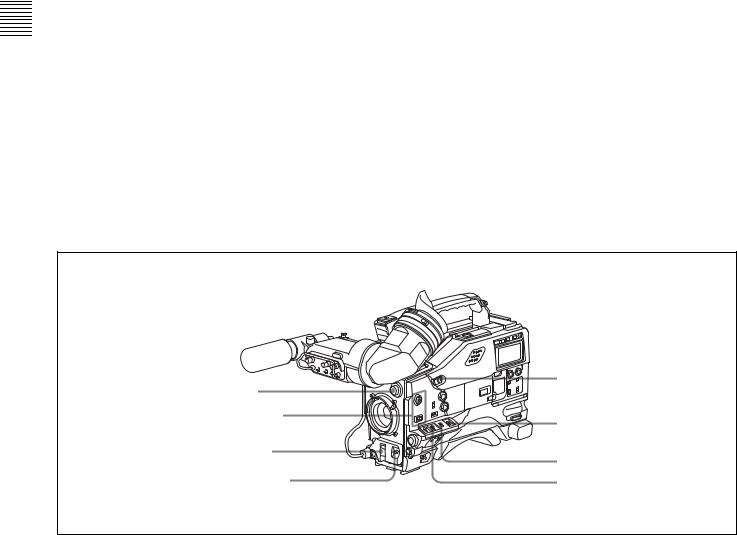
Locations and Functions |
Chapter 2 |
of Parts and Controls |
Controls and Parts of Functions and Locations 2 Chapter
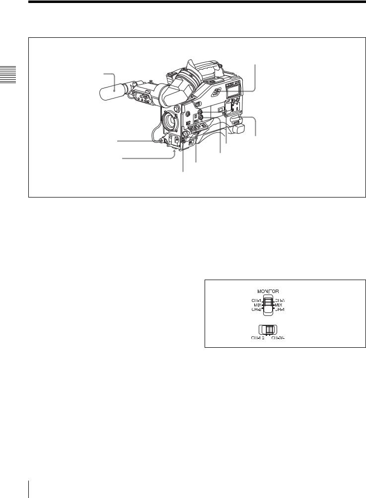
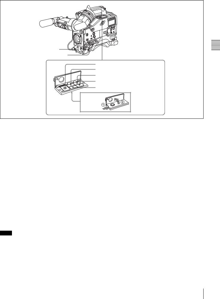
2-1 Power Supply
 aBattery attachment


 bDC IN connector
cPOWER switch
dLIGHT switch
a Battery attachment
Attach a battery pack, BP-GL65, BP-GL95, or BP-L60S. Alternatively, by attaching an AC-DN10 AC Adaptor, you can operate the camcorder from AC power.
b DC IN connector (XLR type, 4-pin, male)
To operate the camcorder using an AC power supply, connect an AC-550/550CE AC Adaptor with the DC output cable supplied with the adaptor.
To use an external battery, connect its DC output cable to the DC IN connector.
When this connector is not being used, attach the supplied XLR connector cover onto it.
c POWER switch
Turns the main power supply on and off.
d LIGHT switch
Determines how a video light connected to the LIGHT connector is turned on and off.
AUTO: When the switch on the video light is in the on position, putting the camcorder in recording mode turns the video light on automatically. When using the auto interval recording mode, the video light is automatically turned on immediately before recording starts.
MANUAL: You can turn the video? light on or off manually, using its own switch.
16 Power Supply

2-2 Accessory Attachments
aShoulder strap posts
bLight shoe
cLIGHT connector
dLens mount
eLens mount lever
fLens mount cap
gLENS connector
iShoulder pad |
|
|
hTripod mount |
||
Lens cable clamp
a Shoulder strap posts
Attach the supplied shoulder strap to these posts.
For details, see “7-7 Attaching/Detaching the Shoulder Strap” on page 127.
b Light shoe
Attach an optional accessory such as a video light to this shoe.
c LIGHT connector (2-pin, female)
Connect the cable of an Anton Bauer Ultralight System attached to the light shoe. The system operates with lights powered by 12 V, with a maximum power consumption of 50 W.
d Lens mount (special bayonet mount)
Use this for mounting the lens.
e Lens mount lever
After inserting the lens in the lens mount, rotate the lens mount ring with this lever to lock the lens in position.
f Lens mount cap
Remove this cap by pushing up the lens mounting lever. When no lens is mounted, keep this cap fitted for protection from dust.
g LENS connector (12-pin)
Fit the lens cable to this connector. Contact your Sony representative for more information about the lenses you can use.
h Tripod mount
When using the camcorder on a tripod, attach the tripod adaptor (optional).
i Shoulder pad
You can move the shoulder pad forwards or backwards by raising up the shoulder pad locking lever. Do this to ensure the best balance when shooting with the camcorder on your shoulder.
For details, see “7-8 Adjusting the Shoulder Pad Position” on page 128.
Controls and Parts of Functions and Locations 2 Chapter
Accessory Attachments |
17 |
|
|
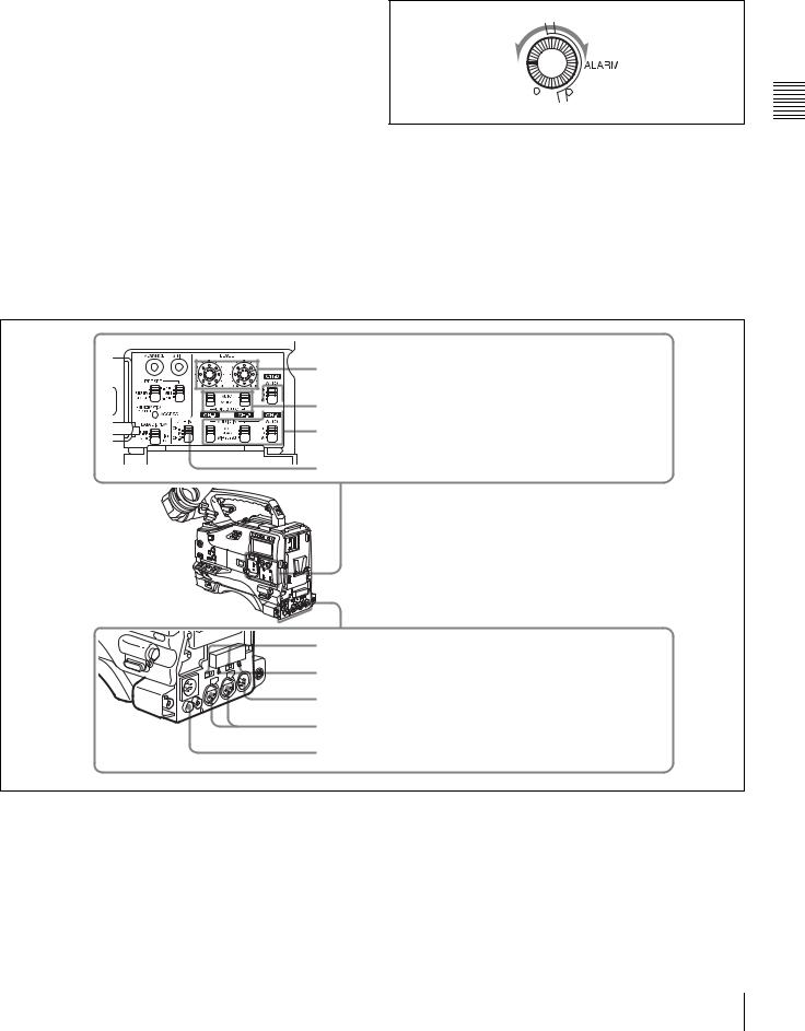
2-3 Audio Functions
Controls and Parts of Functions and Locations 2 Chapter
aMicrophone
bMIC IN connector
cMIC LEVEL control
hBuilt-in speaker
 dEARPHONE jack (rear) gALARM volume control
fMONITOR volume control
eMONITOR switch and CH-1/2 / CH-3/4 switch dEARPHONE jack (front)
Audio functions (1)
a Microphone
This is a supplied directivity super-cardioid stereo microphone with an external power supply (+48 V) system.
Assigning the F.MIC MONO/STEREO function to the ASSIGN 1 switch, ASSIGN 2 switch, or TURBO GAIN button allows you to switch the output signal of the microphone connected to the MIC IN connector between stereo and monaural sound.
For details, see “5-3-5 Assigning Functions to Assignable Switches” on page 95.
b MIC IN (microphone input) connector (XLR type,
5-pin, female)
Connect the supplied microphone to this connector. A microphone other than the supplied one may also be connected if it can operate with the power (+48 V) supplied from this connector.
c MIC (microphone) LEVEL control
Adjusts the audio level of the microphone connected to the MIC IN connector.
d EARPHONE jacks (minijacks)
You can monitor the E-E sound 1) during recording and play back sound during playback. Plugging an earphone into the jack automatically cuts off the built-in speaker.
When an alarm is indicated, you can hear the alarm sound through the earphone.
You can connect earphones to both connectors at the same time.
1)E-E: Abbreviation of “Electric-to-Electric.” In E-E mode, video and audio signals input to the camcorder are output after passing through internal electric circuits only. This can be used to check input signals.
e MONITOR switch and CH-1/2 / CH-3/4 switch
Determine the channel selection for audio monitor output.
MONITOR switch
CH-1/2 / CH-3/4 switch
CH-1/2 / CH-3/4 switch:
Determines the pair of audio channels selected with the MONITOR switch.
CH-1/2 position: channels 1 and 2 CH-3/4 position: channels 3 and 4
The signals output from the AUDIO OUT connector and EARPHONE jacks and the audio level meter in the display window also depend on the setting of this switch.
MONITOR switch:
Selects the audio monitor channels output to the earphone or speaker, depending on the setting of the CH-1/2 / CH-3/ 4 switch.
18 Audio Functions
CH-1/2 / |
MONITOR |
Audio output |
CH-3/4 switch |
switch |
|
position |
position |
|
CH-1/2 |
CH-1 |
Audio channel 1 |
|
|
|
|
MIX |
Mix sound of channels 1 and 2 |
|
|
|
|
CH-2 |
Audio channel 2 |
|
|
|
CH-3/4 |
CH-3 |
Audio channel 3 |
|
|
|
|
MIX |
Mix sound of channels 3 and 4 |
|
|
|
|
CH-4 |
Audio channel 4 |
|
|
|
g ALARM volume control
Adjusts the speaker or earphone alarm volume. At the minimum position, no sound can be heard.
Minimum Maximum
f MONITOR volume control
Adjusts the speaker or earphone volume for sounds other than the alarm sound. At the minimum position, no sound can be heard.
h Built-in speaker
The speaker can be used to monitor E-E sound during recording, and play back sound during playback. The speaker also sounds alarms to reinforce visual warnings. If you connect an earphone to the EARPHONE jack, the speaker is automatically muted.
See “8-4 Operation Warnings” on page 138 for information about alarms.
iLEVEL (CH-1/CH-2) controls
jAUDIO SELECT (CH-1/CH-2) switches kAUDIO IN CH-1/CH-2/CH-3/CH-4 switches
lCUE IN switch
mLINE / AES/EBU / MIC selectors n+48V/OFF switches
oAUDIO OUT connector
pAUDIO IN CH1/CH2 connectors qDC OUT 12V connector
Audio functions (2)
i LEVEL (CH-1/CH-2) (audio channel-1 and |
j AUDIO SELECT (CH-1/CH-2) (audio channel-1 |
channel-2 recording level) controls |
and channel-2 adjustment method selection) switches |
Adjust the audio levels of channels 1 and 2 when the |
Select the audio level adjustment method for each of audio |
AUDIO SELECT switches are set to MANUAL. |
channels 1 and 2. |
|
AUTO: Select this setting for automatic adjustment. |
|
MANUAL: Select this setting for manual adjustment. |
Controls and Parts of Functions and Locations 2 Chapter
Audio Functions 19

Controls and Parts of Functions and Locations 2 Chapter
k AUDIO IN CH-1/CH-2 / CH-3/CH-4 (audio input selection) switches
CH-1/CH-2 switches
Select the audio input signals to be recorded on audio channels 1 and 2.
FRONT: The input signal source is the microphone connected to the MIC IN connector.
REAR: The input signal source is the audio equipment connected to the AUDIO IN CH1/CH2 connectors.
WIRELESS: The input signal source is an optional WRR855A/855B UHF Synthesized Tuner Unit.
CH-3/CH-4 switches
Select the audio input signals to be recorded on audio channels 3 and 4.
F (front): The input signal source is the microphone connected to the MIC IN connector.
R (rear): The input signal source is the audio equipment connected to the AUDIO IN CH1/CH2 connectors.
W (wireless): The input signal source is an optional WRR855A/855B UHF Synthesized Tuner Unit.
l CUE IN (cue track input) switch
Selects the input signal to be recorded on the cue track. CH-1: Signal selected by the AUDIO IN CH-1 switch MIX: Mixed signals selected by the AUDIO IN CH-1 and
CH-2 switches
CH-2: Signal selected by the AUDIO IN CH-2 switch
Note
When recording mixed signals by setting this switch to MIX, be sure to confirm that the emphasis settings of the two channels (on/off) are the same. If they are different, the camcorder cannot record or play back mixed signals correctly.
When the AES/EBU format audio signal is selected, the emphasis settings are determined by the channel status of the AES/EBU format audio signal (emphasis bit).
When an audio signal other than the AES/EBU format audio signal is selected, the emphasis setting depends on the setting of AU REC EMPHASIS (page 158) on the AUDIO-2 page of the MAINTENANCE menu.
m LINE / AES/EBU / MIC selectors
Select the audio source of the audio input signals input to the AUDIO IN CH1/CH2 connectors.
LINE: Line input audio equipment AES/EBU: AES/EBU format audio signal MIC: Microphone input
Note
If this selector is set to the MIC position and the +48V/ OFF switch is set to +48V, and if you inadvertently connect any audio device other than a microphone to the AUDIO IN CH1/CH2 connectors, the device may be damaged.
n +48V/OFF switches
Select either of the following positions for the microphones to be connected.
+48V: For a microphone to use an external power supply OFF: For a microphone to use an internal power supply
o AUDIO OUT (audio output) connector (XLR type,
5-pin, male)
Outputs the audio signals recorded on audio channels 1 and 2 or audio channels 3 and 4.
The MONITOR switch and CH-1/2 / CH-3/4 switches allow you to select the audio signal to be monitored. When this connector is not being used, attach the supplied XLR connector cover onto it.
p AUDIO IN CH1/CH2 (audio channel-1 and channel-2 input) connectors (XLR type, 3-pin, female)
These are audio input connectors for channels 1 and 2 to which you can connect audio equipment or a microphone. When the LINE / AES/EBU / MIC selector is set to AES/ EBU, the CH1 connector is used for channel-1 and -2 inputs, and the CH2 connector, for channel-3 and -4 inputs. When the connector is not being used, attach the supplied XLR connector cover onto it.
q DC OUT 12 V (DC power output) connector (4-pin, female)
Supplies power for an optional WRR-861A/861B/862A/ 862B UHF Portable Tuner. Do not connect any equipment other than the UHF portable tuner.
20 Audio Functions
2-4 Shooting and Recording/Playback Functions
aViewfinder |
hDiopter adjustment ring |
|
|
bTALLY indicator |
Eyecup |
|
|
cBRIGHT control |
|
dCONTRAST control |
|
ePEAKING control
fZEBRA switch
gTALLY switch
jViewfinder left-right positioning ring kCamera operator tally indicator
iViewfinderfront-rear lViewfinder stopper positioning lever
mLOCK knob
Shooting and recording/playback functions (1)
a Viewfinder (when an optional HDVF-20A is used)
Lets you view the image in black and white while shooting, recording or playing back. It also displays various warnings and messages related to the settings or operating conditions of the camcorder, a zebra pattern, safety zone marker 1), and center marker 2).
1)The safety zone marker is a rectangle indicating the effective picture area.
2)The center marker indicates the center of the picture with a crosshair.
For details, see “5-2-5 Setting Marker Display” on page 86.
b TALLY indicator
Setting the TALLY switch to HIGH or LOW enables this indicator. The indicator lights during recording on the VTR. Like the REC indicator in the viewfinder, it flashes to indicate a problem. You can set the indicator brightness with the TALLY switch.
c BRIGHT (brightness) control
Adjusts the picture brightness on the viewfinder screen. It has no effect on the camera output signal.
d CONTRAST control
Adjusts the picture contrast on the viewfinder screen. It has no effect on the camera output signal.
e PEAKING control
Adjusts the sharpness of the picture on the viewfinder screen to make focusing easier. It has no effect on the camera output signal.
f ZEBRA switch
Controls the zebra pattern1) on the viewfinder screen. ON: The zebra pattern is displayed and stays.
OFF: No zebra pattern is displayed.
MOMENT: The zebra pattern is displayed and stays for 5 to 6 seconds.
The zebra pattern is factory set to indicate picture areas where the video level is approximately 70%. You can use the setup menu to change the setting so that areas where the video level is 100% and above are also displayed at the same time.
1)The zebra pattern is picture areas where the video level is approximately 70 % and 100 % or more. It is used as a guide when adjusting the iris manually.
Controls and Parts of Functions and Locations 2 Chapter
Shooting and Recording/Playback Functions |
21 |
|
|
Controls and Parts of Functions and Locations 2 Chapter
For information about how to change the zebra pattern setting in the setup menu, see “5-2-6 Setting the Viewfinder” on page 87.
You can assign the function of the ZEBRA switch to the ASSIGN 1 switch, ASSIGN 2 switch, or TURBO GAIN button on the FUNCTION 1 page of the USER menu.
For details, see “5-3-5 Assigning Functions to Assignable Switches” on page 95.
g TALLY switch
Controls the TALLY indicator, setting its brightness (HIGH or LOW) or turning it off.
HIGH: The TALLY indicator brightness is high. OFF: The TALLY indicator is off.
LOW: The TALLY indicator brightness is low.
h Diopter adjustment ring
Adjusts the viewfinder image for your vision.
i Viewfinder front-rear positioning lever
To adjust the viewfinder position in the front-rear direction, loosen this lever and the LOCK knob. After adjustment, retighten this lever and the LOCK knob.
j Viewfinder left-right positioning ring
Loosen this ring to move the viewfinder sideways.
k Camera operator tally indicator
Lights while the camcorder is recording.
Slide the window open when you shoot with your eye away from the viewfinder. This indicator flashes when the battery level is running low or the tape is almost full.
l Viewfinder stopper
Pull up this stopper to detach the viewfinder from the camera.
m LOCK knob
To adjust the viewfinder position in the front-rear direction, loosen this knob and the viewfinder front-rear positioning lever. After adjustment, retighten this knob and the viewfinder front-rear positioning lever.
uTURBO GAIN button
nFILTER selector |
|
oASSIGN 1/2 switches |
tWHITE BAL switch |
|
|
pSHUTTER selector |
sOUTPUT/DCC switch |
|
|
qAUTO W/B BAL switch |
rGAIN selector |
|
Shooting and recording/playback functions (2)
n FILTER selector
Selects the most appropriate filter to match the light source illuminating the subject.
When this selector is used with the display mode set to 3, the new setting appears on the viewfinder screen for about 3 seconds. (e.g.: ND: 1, CC: B)
The relationships between the selector settings and filter selections as well as examples of filters for different shooting conditions are as follows:
FILTER selector (outer knob) setting and CC filter selection
FILTER selector (outer knob) setting |
CC filter selection |
A |
Cross filter 1) |
B |
3200K |
|
|
C |
4300K |
|
|
D |
6300K |
|
|
1) A special effect filter. Creates a 4-point star effect on highlighted area.
22 |
Shooting and Recording/Playback Functions |
|
|
FILTER selector (inner knob) setting and ND filter selection
FILTER selector (inner knob) setting ND filter selection
1 |
Clear |
2 |
1/4 ND |
3 |
1/16 ND |
4 |
1/64 ND |
Examples of shooting conditions and appropriate filters
Shooting condition |
CC filter |
ND filter |
|
Sunrise and sunset; inside |
B (3200K) |
1 |
(clear) |
studio |
|
|
|
|
|
|
|
Clear skies |
C (4300K) or |
2 |
(1/4 ND) or |
|
D (6300K) |
3 |
(1/16 ND) |
Cloudy or raining |
D (6300K) |
1 (clear) or |
|
|
|
2 |
(1/4 ND) |
Very bright conditions such |
C (4300K) or |
3 |
(1/16 ND) or |
as snow, at high altitudes, |
D (6300K) |
4 |
(1/64 ND) |
or at the seashore |
|
|
|
o ASSIGN 1/2 switches
You can assign the desired functions to each of the ASSIGN 1 switch (push button) and ASSIGN 2 switch (sliding) on the FUNCTION 1 page of the USER menu.
For details, see “5-3-5 Assigning Functions to Assignable Switches” on page 95.
p SHUTTER selector
Set this selector to ON to use the electronic shutter. Push it down to SELECT to switch the shutter speed or mode setting within the range previously set with the setup menu.
When this selector is operated, the new setting appears on the viewfinder screen for about 3 seconds.
For details about the shutter speed and mode settings, see “4-2 Setting the Electronic Shutter” on page 61.
q AUTO W/B BAL (automatic white/black balance adjustment) switch
Activates the white balance and black balance automatic adjustment functions.
WHT: Automatic adjustment of the white balance. If the WHITE BAL switch is set to A or B, the white balance setting is stored in the corresponding memory. The memory stores a separate white balance setting for each filter setting.
BLK: Automatic adjustment of the black set and black balance.
r GAIN selector
Switches the gain of the video amplifier to match the lighting conditions during shooting. The gains corresponding to the L, M, and H settings can be selected
from the setup menu. The factory settings are L = 0 dB, M = 6 dB, and H = 12 dB.
When this selector is adjusted, the new setting appears on the viewfinder screen for about 3 seconds.
For details about setting the gain values, see “5-3-1 Setting Gain Values for the GAIN Selector Positions” on page 92.
s OUTPUT/DCC (output signal/dynamic contrast control) switch
Switches the video signal that is output to the VTR, viewfinder, and video monitor, between the following: BARS: Outputs the color bar signal.
CAM: Outputs the video signal from the camera. When this is selected, you can switch DCC1) on and off with this selector.
1)DCC (Dynamic Contrast Control)
Against a very bright background with the iris opening adjusted to the subject, objects in the background will be lost in the glare. The DCC function will suppress the high intensity and restore much of the lost detail and is particularly effective in the following cases.
•Shooting people in the shade on a sunny day
•Shooting a subject indoors, against a background through a window •Any high contrast scene
BARS, DCC OFF
A color bar signal is output and the DCC circuit does not operate. For example, use the setting for the following purposes.
•Adjusting the video monitor
•Recording the color bar signal
CAM, DCC OFF
The video signal from the camera is output, and the DCC circuit does not operate.
CAM, DCC ON
The video signal from the camera is output, and the DCC circuit operates.
OUTPUT/DCC switch
t WHITE BAL (white balance memory) switch
Controls the white balance setting.
PRST (preset): Adjusts the color temperature corresponding to the position of the FILTER selector. Use the PRST setting when you have no time to adjust the white balance.
A or B: When the AUTO W/B BAL switch is pushed to WHT, the white balance is automatically adjusted according to the current position of the FILTER selector, and the adjusted value is stored in either memory A or memory B. (There are two memories for each filter, allowing a total of eight adjustments to be stored.) When this switch is set to A or B, the camcorder automatically adjusts itself to the stored value corresponding to the current settings of this switch and the FILTER selector.
Controls and Parts of Functions and Locations 2 Chapter
Shooting and Recording/Playback Functions |
23 |
|
|

Controls and Parts of Functions and Locations 2 Chapter
You can use the AUTO W/B BAL switch even when ATW1) is in use.
1)ATW (Auto Tracing White Balance)
The white balance of the picture being shot is adjusted automatically for varying lighting conditions.
B (ATW): When this switch is set to B and on the FUNCTION 2 page of the OPERATION menu, WHITE SWITCH<B> (page 145) is set to ATW, ATW is activated.
When this switch is adjusted, the new setting appears on the setting change/adjustment progress message display area of the viewfinder screen for about 3 seconds.
You can assign the ATW ON/OFF function to the ASSIGN 1 switch (push button) on the FUNCTION 1 page of the USER menu.
For details, see “5-3-5 Assigning Functions to Assignable Switches” on page 95.
u TURBO GAIN button
When shooting under extremely poor lighting conditions, press the button once to boost the video gain to the value preset on the GAIN SW page of the USER menu (up to 42 dB). To stop boosting the gain, press the button once more. The gain is reset to the original gain. You can assign the desired function to this TURBO GAIN button like the ASSIGN 1 switch on the FUNCTION 1 page of the USER menu.
For details, see “5-3-5 Assigning Functions to Assignable Switches” on page 95.
vHD-SDI OUT connector |
|
wHD-SDI OUT connector |
xTEST OUT connector |
|
yREMOTE connector |
Shooting and recording/playback functions (3)
v HD-SDI OUT connector (BNC type) w HD-SDI OUT connector (BNC type)
Output an HD-SDI signal for a video monitor. You can select whether or not the signal is output from these connectors using the OUTPUT SEL page of the USER menu.
When an optional HKDW-702 extension board is attached to the camcorder, the camcorder outputs either a downconverted analog composite signal (color) or an SD SDI signal from the HD-SDI OUT connector located on the side. You can select which signal is output on the OUTPUT SEL page of the USER menu.
For details on how to select the output signal, see “5-3-2 Selecting Output Signals” on page 93.
x TEST OUT (test output) connector (BNC type)
Outputs an HD-Y (standard level, 75-ohm terminated) signal for the video monitor.
When an optional HKDW-702 extension board is attached to the camcorder, you can select either a down-converted analog composite signal (color) or an HD-Y signal on the OUTPUT SEL page of the USER menu.
For details on how to select the output signal, see “5-3-2 Selecting Output Signals” on page 93.
Depending on menu settings, menus, time code, and shot data can be superimposed on the image on the monitor.
y REMOTE connector (8-pin)
Connect the RM-B150/B750 Remote Control Unit, which makes it possible to control the VTR and camera remotely.
24 |
Shooting and Recording/Playback Functions |
|
|
zVTR START button
wj VTR SAVE/STBY switch
wk EJECT button
wl REW button and indicator e; F FWD button and indicator ea PLAY button and indicator es STOP button
Shooting and recording/playback functions (4)
z VTR START button
Press this button to start recording. Press it again to stop recording. The effect is exactly the same as that of the VTR button on the lens.
When the REC SWITCH function is assigned to the ASSIGN 1 switch (push button), you can use the switch as the VTR START button.
For details, see “5-3-5 Assigning Functions to Assignable Switches” on page 95.
wj VTR SAVE/STBY (standby) switch
Controls the VTR power mode during pauses in recording. SAVE: Power saving mode. When you press the VTR
START button, there is a short delay before recording starts, but power consumption in this mode is less than in standby mode. As a result, battery life is extended. When the switch is set to SAVE, the VTR SAVE indicator in the viewfinder lights.
STBY: Standby mode. Recording starts as soon as you press the VTR START button.
Notes
•Avoid allowing the camcorder to remain in STBY (standby) mode for a long time.
•Even if the switch is set to the STBY position, the camcorder can automatically turn to power saving mode if the tape does not run for a certain period. In such a case, the VTR SAVE indicator in the viewfinder lights. This function is effective when a setting other than OFF is selected for the STBY OFF TIMER item on the VTR
MODE page of the MAINTENANCE menu. The STBY OFF TIMER item also allows you to select the length of time until the camcorder turns to power saving mode.
For detailed information, see “3-6 Setting the Stand-by off Timer During Rec-Pause” on page 57.
wk EJECT button
Press this button to eject or load a cassette.
wl REW (rewind) button and indicator
Press this button to rewind the tape. The indicator lights during rewinding.
e; F FWD (fast forward) button and indicator
Press this button to fast forward the tape. The indicator lights during fast forward.
ea PLAY button and indicator
Press this button to view the recorded picture in the viewfinder or on the color video monitor. The indicator lights during playback.
The four times normal speed search function is provided to make it far quicker to find a desired location of the tape. Press the REW button or F FWD button during playback to view the four times normal speed search picture.
es STOP button
Press this button to stop the tape.
Shooting and Recording/Playback Functions
Controls and Parts of Functions and Locations 2 Chapter
25

Controls and Parts of Functions and Locations 2 Chapter
2-5 Menu Operating Section
a“Memory Stick” compartment |
cSTATUS ON/SEL / OFF switch |
dMENU ON/OFF switch |
eCANCEL/PRST / ESCAPE switch |
Switch cover |
bMENU knob |
a “Memory Stick” compartment
ACCESS indicator
MEMORY STICK OPEN button
f
“Memory Stick” Eject button
Open the cover of the “Memory Stick” compartment by pressing the MEMORY STICK OPEN button and insert the “Memory Stick.”
To remove, press the eject button.
During data writing/loading to/from the “Memory Stick,” the ACCESS indicator lights or flashes.
For details, see “6-1-1 Handling the “Memory Stick”” on page 107.
b MENU knob
Changes the page selection or a setting within the menu. Push: If you push this knob when the arrow (b) is placed at the page title on the menu, the arrow changes to a question mark (?) and you can change the page by
turning this knob.
When the arrow mark is placed at a position other than the page title, you can change the setting of the current item by pushing and turning this knob.
Turn: Turn this knob to change the page or change item settings.
c STATUS ON/SEL / OFF (menu display on/page selection/display off) switch
To enable this switch, set the MENU ON/OFF switch to OFF.
Closing the switch cover automatically sets the MENU ON/OFF switch to OFF.
ON/SEL: Each time this switch is pushed upward, a window to confirm the menu settings and status of the camcorder appears on the viewfinder screen. The window consists of three pages, which are switched each time the switch is pushed upward. Each page is displayed for about 10 seconds.
OFF: To clear the page immediately after display, push this switch down to the OFF position.
You can select the pages to be displayed on the menu.
For details, see “5-2-9 Displaying the Status Confirmation Windows” on page 90.
d MENU ON/OFF switch
To use this switch, open the switch cover.
This switch is used to display the menu on the viewfinder screen or the test signal screen.
26 |
Menu Operating Section |
|
|

Closing the cover automatically sets this switch to OFF. ON: Displays the menu on the viewfinder screen or the test
signal screen, at the last accessed page. When the menu is used for the first time, the first page is displayed.
OFF: Removes the menu from the viewfinder screen or the test signal screen.
e CANCEL/PRST (preset) / ESCAPE switch
To enable this switch, set the MENU ON/OFF switch to ON.
Closing the cover automatically sets the MENU ON/OFF switch to OFF.
CANCEL/PRST: Pushing this switch up to this position displays the message to confirm whether the previous settings are cancelled or settings are reset to their initial values, depending on the menu operating condition.
Pushing this switch up to this position again cancels the previous settings or resets the settings to their initial values.
ESCAPE: Use this switch when the menu page, which has a hierarchical structure, is opened. Each time the switch is pushed to this position, the page returns to one stage higher in the hierarchy.
Controls and Parts of Functions and Locations 2 Chapter
Menu Operating Section |
27 |
|
|
2-6 Time Code System
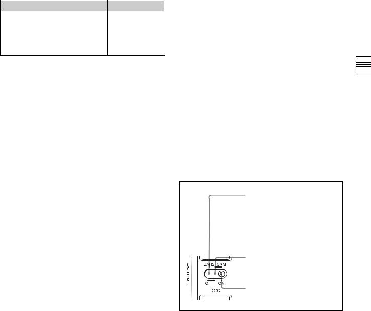
Controls and Parts of Functions and Locations 2 Chapter
aGENLOCK IN connector
bTC IN connector
cTC OUT connector
Time code functions (1)
a GENLOCK IN connector (BNC type)
•This connector inputs an HD reference signal when the camera is to be genlocked or when the time code is to be synchronized with external equipment.
•When the time code is to be synchronized with external equipment, this connector can input an NTSC/PAL analog composite signal as the reference video signal.
•This connector also inputs a return video signal. You can display the image of the return video signal on the viewfinder screen when you set RETURN VIDEO to ON on the GENLOCK page of the MAINTENANCE menu.
You can assign the RETURN VIDEO function to the ASSIGN 1 switch.
For details, see “5-3-5 Assigning Functions to Assignable
Switches” on page 95.
b TC IN (time code input) connector (BNC type)
To synchronize the time code of this camcorder to an external time code, input the reference time code to this connector.
c TC OUT (time code output) connector (BNC type)
To synchronize the time code of an external VTR to that of the camcorder, connect this connector to the reference time code input connector of the external VTR.
28 Time Code System
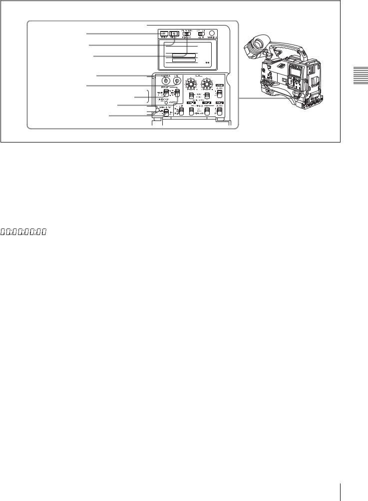
dHOLD button |
eRESET button |
fDISPLAY switch |
gADVANCE button |
hSHIFT button |
iPRESET/REGEN/CLOCK switch |
jF-RUN/SET/R-RUN switch |
kDATA DISPLAY switch |
Time code functions (2)
d HOLD (display hold) button
Pressing this button instantly freezes the time data displayed in the counter display section. (The time code generator continues running.) Pressing this button again releases the hold. You can use this button, for example, to determine the exact time of a particular shot.
When the HOLD button is activated, the time data is displayed in the following format:
PRESET: Records time code with a preset initial value. REGEN: Records time code continuous with the existing time code recorded on the tape. Regardless of the
setting of the F-RUN/SET/R-RUN switch, the camcorder operates in R-RUN mode.
CLOCK: Records time code synchronized to the internal clock. Regardless of the setting of the F-RUN/SET/R- RUN switch, the camcorder operates in F-RUN mode.
Controls and Parts of Functions and Locations 2 Chapter
For details of the counter display, see “2-8 Warnings and Indications on the Display Panel” on page 31.
e RESET button
Pressing this button resets the time data displayed on the counter display section to “00:00:00:00” or the user bit data to “00000000.”
f DISPLAY (LCD display) switch CTL: Displays control signal
TC: Displays time code
DATA: Displays the item selected by the DATA DISPLAY switch.
For details, see “Time code display” on page 32.
g ADVANCE button
For setting the time code, user bits, or real time, each press of this button increments the flashing digit selected by the SHIFT button.
h SHIFT button
For setting the time code, user bits, or real time, this button selects the digit to be changed. The selected digit flashes.
i PRESET/REGEN (regeneration)/CLOCK switch
This switch selects whether to set a new time code or to follow the already recorded time code.
For more information, see “To make the time code consecutive” on page 71.
j F-RUN/SET/R-RUN (free run/set/recording run) switch
This switch selects the operating mode for the internal time code generator.
F-RUN: Time code keeps advancing, regardless of the operating state of the VTR. Use this setting when aligning the time code with real time or when synchronizing the time code with an external time code.
SET: Set the switch to this position to set the time code or user bits.
R-RUN: The time code value advances only during recording. Use this setting to have a consecutive time code on the tape.
For details, see “4-5-1 Setting the Time Code” on page 70 and “4-5-3 Setting the User Bits” on page 71.
k DATA DISPLAY switch U-BIT: Displays the user bit value
SHOT TIME: Displays the date and time from the shot data
SHOT-NO: Not used
Time Code System 29

Controls and Parts of Functions and Locations 2 Chapter
2-7 Warnings and Indications
Besides the viewfinder, speaker and earphones, the indicators and displays described in this section also provide you with information such as the operating state of the camcorder and warnings.
aTALLY indicator
bDISPLAY/ASPECT switch
cTALLY switch
dBACK TALLY indicator eBACK TALLY switch fLCD LIGHT switch
gWARNING indicator hDisplay panel
iREAR TALLY indicator
a TALLY indicator
Setting the TALLY switch on the viewfinder to HIGH or LOW enables this indicator. It lights when the VTR starts recording. Like the REC indicator in the viewfinder, it also flashes to provide warnings. The brightness of this indicator when it is lit can be switched with the TALLY switch.
b DISPLAY/ASPECT (display/aspect control) switch
Turns the markers on or off and changes the viewfinder screen aspect ratio.
DISPLAY: When the MARKER is set to ON on the MARKER 1 page of the USER menu, pushing this switch to DISPLAY toggles the markers on the viewfinder screen on and off.
ASPECT: Pushing this switch to ASPECT toggles the viewfinder screen aspect ratio between 16 : 9 and 4 : 3.
For details, see “5-2-5 Setting Marker Display” on page 86.
Note
Setting the MENU ON/OFF switch to ON displays the menu on the viewfinder screen even if the DISPLAY switch is set to OFF.
c TALLY switch
Controls the TALLY indicator as follows: HIGH: The TALLY indicator brightness is high. OFF: The TALLY indicator is off.
LOW: The TALLY indicator brightness is low.
d BACK TALLY indicator
When the BACK TALLY switch is set to ON, this indicator has the same function as the TALLY indicator.
e BACK TALLY switch
Enables or disables the BACK TALLY and REAR TALLY indicators.
ON: The BACK TALLY and REAR TALLY indicators are enabled.
30 |
Warnings and Indications |
|
|
Loading...