


SIGNAL PROCESSING UNIT
PFV-SP3100
BACKUP POWER SUPPLY UNIT
HK-PSU01
INSTALLATION MANUAL
1st Edition
Serial No. 10001 and Higher (PFV-SP3100)
Serial No. 10001 and Higher (HK-PSU01)
! WARNING
This manual is intended for qualified service personnel only.
To reduce the risk of electric shock, fire or injury, do not perform any servicing other than that
contained in the operating instructions unless you are qualified to do so. Refer all servicing to
qualified service personnel.
! WARNUNG
Die Anleitung ist nur für qualifiziertes Fachpersonal bestimmt.
Alle Wartungsarbeiten dürfen nur von qualifiziertem Fachpersonal ausgeführt werden. Um die
Gefahr eines elektrischen Schlages, Feuergefahr und Verletzungen zu vermeiden, sind bei
Wartungsarbeiten strikt die Angaben in der Anleitung zu befolgen. Andere als die angegeben
Wartungsarbeiten dürfen nur von Personen ausgeführt werden, die eine spezielle Befähigung
dazu besitzen.
! A VERTISSEMENT
Ce manual est destiné uniquement aux personnes compétentes en charge de l’entretien. Afin
de réduire les risques de décharge électrique, d’incendie ou de blessure n’effectuer que les
réparations indiquées dans le mode d’emploi à moins d’être qualifié pour en effectuer d’autres.
Pour toute réparation faire appel à une personne compétente uniquement.
For the U.S.A (PFV-SP3100)
Attention-when the product is installed in Rack:
1. Prevention against overloading of branch circuit
When this product is installed in a rack and is
supplied power from an outlet on the rack, please
make sure that the rack does not overload the supply
circuit.
2. Providing protective earth
When this product is installed in a rack and is
supplied power from an outlet on the rack, please
confirm that the outlet is provided with a suitable
protective earth connection.
3. Internal air ambient temperature of the rack
When this product is installed in a rack, please make
sure that the internal air ambient temperature of the
rack is within the specified limit of this product.
4. Prevention against achieving hazardous
condition due to uneven mechanical loading
When this product is installed in a rack, please make
sure that the rack does not achieve hazardous
condition due to uneven mechanical loading.
5. Install the equipment while taking the operating
temperature of the equipment into consideration
For the operating temperature of the equipment, refer
to the specifications of the Operation Manual.
6. When performing the installation, keep the rear of
the unit 10 cm (4 inches) or more away from walls
in order to obtain proper exhaust and radiation of
heat.
PFV-SP3100

Table of Contents
Manual Structure
Purpose of this manual ........................................................................................ 2 (E)
Related manuals................................................................................................... 2 (E)
1. Installation
1-1. Operating Environment .........................................................................1-1 (E)
1-2. Power Supply ........................................................................................1-1 (E)
1-2-1. Power Supply Specifications................................................1-1 (E)
1-2-2. Recommended Power Cord..................................................1-1 (E)
1-3. Installation Space .................................................................................. 1-2 (E)
1-4. Installing/Removing Optional Power Supply Unit ...............................1-3 (E)
1-5. Installing Optional Board ......................................................................1-4 (E)
1-6. Rack Mounting......................................................................................1-6 (E)
1-6-1. Notes on Rack Mounting .....................................................1-6 (E)
1-6-2. Rack Mounting Procedure....................................................1-6 (E)
1-7. Matching Connector/Cable ...................................................................1-8 (E)
1-8. Signal Inputs/Outputs............................................................................1-8 (E)
2. Service Overview
2-1. Cleaning the Filter.................................................................................2-1 (E)
2-2. Periodic Replacement Parts to Be Recommended ................................2-1 (E)
PFV-SP3100
1 (E)

Purpose of this manual
Related manuals
Manual Structure
This manual is the installation manual of Signal Processing Unit PFV-SP3100 and
its Backup Power Supply Unit HK-PSU01.
This manual is intended for use by trained system and service engineers, and
describes the information for installation of the unit.
n
The functions and specifications of HK-PSU01 and PFV-SP3100’s power supply
unit are equal. This manual uses “Power Supply Unit” for HK-PSU01 and PFVSP3100’s power supply unit.
The following manuals are prepared for PFV-SP3100.
..
. Operation Manual (Supplied with PFV-SP3100)
..
This manual describes the notes on operating, the locations and functions of parts,
and controls of PFV-SP3100.
..
. Maintenance Manual (Available on request)
..
This manual describes the information for periodic maintenance and detailed
service.
If this manual is required, please contact your local Sony Sales Office/Service
Center.
..
. “Semiconductor Pin Assignments” CD-ROM (Available on request)
..
This “Semiconductor Pin Assignments” CD-ROM allows you to search for
semiconductors used in B&P Company equipment.
Semiconductors that cannot be searched for on this CD-ROM are listed in the
service manual for the corresponding unit. The service manual contains a complete list of all semiconductors and their ID Nos., and thus should be used together
with the CD-ROM.
Part number: 9-968-546-XX
2 (E)
PFV-SP3100
Section 1
Installation
1-1. Operating Environment
Operating temperature +5 dC to +40 dC
Performance temperature +10 dC to +35 dC
Humidity 10 to 90 % (No condensation)
Mass: PFV-SP3100 Approx. 8.5 kg
(Without the optional unit and
board)
HK-PSU01 Approx. 1 kg
To prevent overheating of PFV-SP3100, ensure that there
is good air circulation around the unit.
w
Do not put the unit in a place subject to excessive lamp
smoke, vapor, moisture, or dust, otherwise a fire or electric
shock may result.
c
Install in a stable location.
Installation on unstable or tilting surface may cause the
unit fall off, resulting in injury.
1-2. Power Supply
1-2-1. Power Supply Specifications
Power voltage AC 100 V to 240 V
Power frequency 50 Hz or 60 Hz
Current consumption 1.0 to 0.5 A
Rush current AC 100 V IN : 10 A
AC 240 V IN : 33 A
n
AC power supply is required a capacity which is commensurate with rush current.
If the capacity of the AC power supply is not enough, the
breaker of AC power on the supply side may operate or
this unit may not operate normally.
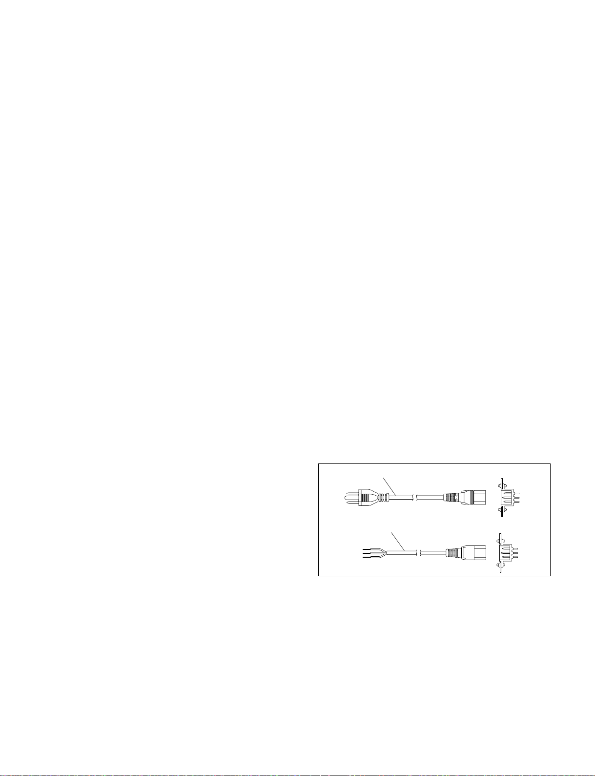
1-2-2. Recommended Power Cord
For customers in the U.S.A. and Canada
Required Part
1 Power cord, 125 V 10 A (2.4 m) : ! 1-557-377-11
For customers in the United Kingdom
Required Part
2 Power cord, 250 V 10 A (2.5 m) : ! 1-782-929-11
1
2
n
For the customers outside of the area as shown above,
please contact your local Sony Sales Office/Service Center.
w
. Use a specified power cord only.
Be sure to use a recommended power cord to avoid fire
and/or an electric shock.
. Ground the unit for your safety.
Be sure to attach a ground wire to avoid an electric shock.
AC inlet
AC inlet
PFV-SP3100
1-1 (E)

1-3. Installation Space
1-3. Installation Space
m
. Do not block the ventilation holes of the unit.
. Both of the front and rear sides must be at least 20 cm away from the walls for ventilation and mainte-
nance.
The outer dimensions of PFV-SP3100 are as shown here:
43.6
550
440
1-2 (E)
482
Unit: mm
PFV-SP3100

1-4. Installing/Removing Optional Power Supply Unit
Handle
HK-PSU01
Indicator
PSW
3x6
1-4. Installing/Removing Optional Power
Supply Unit
w
Before installing the backup power supply unit HK-PSU01
in PFV-SP3100, set the power switch of HK-PSU01 to the
“O” position (OFF).
Otherwise, deterioration of a connector which connects
HK-PSU01 to PFV-SP3100 may cause a fire.
Installation Procedure
1. Loosen the two screws and remove the front panel.
Screw
(with stopper)
3. Make sure that the power switch of the backup power
supply unit HK-PSU01 is set to the “O” position
(OFF).
4. Insert HK-PSU01 into PFV-SP3100 and push it by
hand as far as it will go.
5. Secure HK-PSU01 with the two screws which is
removed in step 2.
c
If installation of the power supply unit is incomplete,
contact resistance of the connector increases and that
may cause damage and smoke.
Tighten firmly the screws that secure the power supply
units.
Do not turn on the power until the power supply units
are firmly secured.
Front panel
Screw
(with stopper)
2. Remove the two screws and remove the blank panel in
the empty slot for the backup power supply unit.
n
Keep the blank panel which is removed.
PSW
3x6
PFV-SP3100
PSW 3x6
Blank panel
6. Reinstall the front panel.
7. Connect the power cord and set the power switch to
the “I” position (ON).
8. Make sure that the indicator lights.
n
If the indicator does not light, turn off the power and
contact your local Sony Sales Office/Service Center.
Removal Procedure
1. Turn off the power of the power supply unit which you
want to remove. (Set the power switch to “O” position.)
2. Unplug the power plug from the wall outlet.
3. Remove the front panel.
4. Remove the screws securing the power supply unit.
5. Pull out the power supply unit from the slot using its
front handle.
6. Install the blank panel.
7. Reinstall the front panel.
1-3 (E)

1-5. Installing Optional Board
1-5. Installing Optional Board
The optional board can be installed in any empty slot of
PFV-SP3100.
When installing the processing module controller, the No.4
slot is used as the master slot and the No.3 slot is used as
the sub-slot.
Installing Main Board (Front side)
Two slots are used depending on the optional board.
In this section, the illustrations for the single-slot type’s
board are described.
1. Turn off the power switches of PFV-SP3100.
n
Turn off both of the power switches when the backup
power supply unit is installed.
2. Remove the front panel. (Refer to Section 1-4.)
3. Loosen the four screws and remove the board retainer.
Power switches
4. Insert the main board fully into the slot along the board
guides and close the board lever in the direction
indicated by arrow 1.
5. Stick the slot label supplied with the PFV-SP3100 onto
the board lever.
n
Attach the supplied slot label to the position where it is
not concealed by the board retainer as shown in the
figure.
Slot 4
4
3
Slot 3
Board guides
Slot 2
2
1
Slot 1
B 3x8
(with stopper)
Board retainer
B 3x8
(with stopper)
Main board
1
Board lever
Board lever
Board retainer
Slot label
1-4 (E)
PFV-SP3100

1-5. Installing Optional Board
6. Reinstall the board retainer.
7. Reinstall the front panel.
n
When removing the main board, turn the board lever in the
direction of the arrow 2 , and pull out the board toward
you.
Main board
2
Board lever
Installing Connector Panel (Rear side)
The connector panel must be installed to the slot which
contains the main board.
1. Remove the two screws and remove the blank panel of
the slot which contains the main board.
n
Keep the removed blank panel and two screws.
B 3x5
Blank panel
2. Connect the connector panel to the MB-992 board.
3. Secure the connector panel with the two screws.
MB-992 board
Screws
Connector panel
n
Do not open the slot for an air-cooled effect of this unit.
Attach the blank panel to an empty slot.
PFV-SP3100
1-5 (E)

1-6. Rack Mounting
1-6. Rack Mounting
PFV-SP3100 can be mounted on a 19-inch standard rack
for use.
Mount PFV-SP3100 on the rack properly in the procedure
below using a specified rack mounting kit.
Specified rack mounting kit: RMM-10
n
PFV-SP3100 may not be able to be mounted on a 19-inch
standard rack using a rack mounting kit other than the
specified one.
Components of RMM-10
. Rack brackets ...........................................................2 pcs
. Rack mounting adaptor (right) ................................. 1 pc
[Including two screws (B 4x6: 7-682-560-09)]
. Rack mounting adaptor (left) ...................................1 pc
[Including two screws (B 4x6: 7-682-560-09)]
. Rack bracket fixing screws (B 4x6: 7-682-560-09)
.......................................................................... 6 pcs
. Adaptor fixing screws (B 4x10: 7-682-560-10) ...... 6 pcs
n
Install a ventilating fan in the rack to prevent the increase
in the temperature inside a rack when multiple units are put
in one rack.
1-6-2. Rack Mounting Procedure
Explains the procedure for rack mounting by Rack Mount
Kit RMM-10.
n
Fasten the screws at the tightening torque below.
Tightening torque: 1.2 N.m {12.2 kgf.cm}
1. Attach the rack brackets in the side panels of the unit
with the specified six screws.
n
Be sure to use B4x6 as a screw.
B 4x6
Rack bracket
Required other parts
To mount the unit on the rack, the following parts are
required.
. Screws for rack mounting (B5x12: 7-682-576-04)
.......................................................................... 4 pcs
1-6-1. Notes on Rack Mounting
w
. Fix the rack on the horizontal and firm floor with bolts to
prevent it from turning over or moving.
If the rack overturn due to the weight of the unit, this
may cause a death or serious injury.
. After rack mounting, be sure to tighten the screws of the
rack angle and fix this unit to the rack.
If not, this unit may slide and fall from the rack. This
causes an injury.
c
Attention when this unit is installed in the rack:
. Use the specified rack mounting kit.
. Be careful not to put your hand or finger in the rack
mount rail.
. Install in a stable posture.
Rack bracket
B 4x6
2. Loosen the screws at the rear of the each adaptor,
before adjusting each adaptor length to the rack depth.
(Following figure is case of left side.)
Rail portion
B 4x6
1-6 (E)
PFV-SP3100

1-6. Rack Mounting
n
The maximum depth of an adaptor is 750 mm.
The minimum depth of an adaptor is 595 mm.
3. Firmly lay the right and left adaptors in the rack with
the specified six screws.
(Following figure is case of left side.)
RMM-10
Front
31.75
B 4x10
Rear
1U
B 4x10
31.75
4. Fasten the length adjustment screws which are
loosened in step 2.
5. Remove the front panel. (Refer to Section 1-4.)
6. Align the crook of the each rack bracket on the side
panels of the unit with the rail, then slide the unit
backward.
n
Each rack bracket covers the rails as shown in the
figure below.
7. Fix the unit to the rack with the specified screws.
B 5x12
B 5x12
8. Reinstall the front panel.
PFV-SP3100
Rack bracket
Rail
Rack bracket
Rail
1-7 (E)

1-7. Matching Connector/Cable
1-8. Signal Inputs/Outputs
1-7. Matching Connector/Cable
When external cables are connected to the connectors on the PFV-SP3100 rear panel, the hardware listed below (or the
equivalent) must be used.
PFV-SP3100 connector Matching connector/cable
Print on Connector type Connector type Sony Part Number
REMOTE BNC, 75Z BNC, 75Z 1-569-370-12
REF IN A/B Belden 1694 coaxial cable –
STATUS OUT D-sub Mini 15-pin, Female D-sub Mini 15-pin, Male –
1-8. Signal Inputs/Outputs
The input and output signals of the connector on the rear panel are as shown here:
STATUS OUT (D-sub Mini 15-pin, female)
51
10 6
15
11
< External view >
Pin No. I/O Signal Function (All pins are low in level Description
1 O PS-A ERROR OUT State of power unit A The output of power unit A is abnormal.
2 O PS-B ERROR OUT State of power unit B The output of power unit B is abnormal.
3 O FAN ERROR OUT State of frame ventilation fan The frame ventilation fan stops.
4 O BOARD ERROR Error status output of optional board Error output from optional board
OUT Overpower consumption from optional board
5 O BOARD WARNING Warning status output of optional board Warning output from optional board
OUT
6 O BOARD ERROR 1 Error status output of board installed in Error output from the optional board installed in
OUT the No.1 slot the No.1 slot.
7 O BOARD ERROR 2 Error status output of board installed in Error output from the optional board installed in
OUT the No.2 slot the No.2 slot.
8 O BOARD ERROR 3 Error status output of board installed in Error output from the optional board installed in
OUT the No.3 slot the No.3 slot.
9 O BOARD ERROR 4 Error status output of board installed in Error output from the optional board installed in
OUT the No.4 slot the No.4 slot.
10 O BOARD WARNING Warning status output of board installed Warning output from the optional board installed
1 OUT in the No.1 slot in the No.1 slot.
11 O BOARD WARNING Warning status output of board installed Warning output from the optional board installed
2 OUT in the No.2 slot in the No.2 slot.
12 O BOARD WARNING Warning status output of board installed Warning output from the optional board installed
3 OUT in the No.3 slot in the No.3 slot.
13 O BOARD WARNING 4 Warning status output of board installed Warning output from the optional board installed
OUT in the No.4 slot in the No.4 slot.
14, 15 – GND
under normal conditions)
The fan of power unit A stops.
The fan of power unit B stops.
1-8 (E)
PFV-SP3100

Section 2
Service Overview
2-1. Cleaning the Filter
w
Be sure to turn off the power switch and disconnect the
power cord from the outlet before starting any work.
c
. The temperature inside the unit increases if dust adheres
to the filter and the ventilation holes are blocked.
Touching inside the unit while it is hot may result in
burn injuries.
. Clean the filter on the rear of the front panel periodically
because the filter tends to gather dust (once every two
months).
Procedure
1. Remove the front panel. (Refer to Section 1-4.)
2. Remove the dust from the filter using a vacuum.
n
If the filter is very dusty, it should be washed in water, and
then dried completely.
2-2. Periodic Replacement Parts to Be
Recommended
The fan used on the rear panel of this unit is periodic
replacement parts to be recommended. The life of the fan
is approximately 50,000 hours. The life corresponds to
about five years and a half if the power is on all the time,
so the fan should be replaced according to service conditions.
n
For the replacement of the fan, refer to the optionally
available PFV-SP3100 Maintenance Manual.
PFV-SP3100
2-1 (E)


The material contained in this manual consists of
information that is the property of Sony Corporation.
Sony Corporation expressly prohibits the duplication of
any portion of this manual or the use thereof for any
purpose other than the operation or maintenance of the
equipment described in this manual without the express
written permission of Sony Corporation.
Le matériel contenu dans ce manuel consiste en
informations qui sont la propriété de Sony Corporation.
Sony Corporation interdit formellement la copie de
quelque partie que ce soit de ce manuel ou son emploi
pour tout autre but que des opérations ou entretiens de
l’équipement à moins d’une permission écrite de Sony
Corporation.
Das in dieser Anleitung enthaltene Material besteht aus
Informationen, die Eigentum der Sony Corporation sind.
Die Sony Corporation untersagt ausdrücklich die
Vervielfältigung jeglicher Teile dieser Anleitung oder den
Gebrauch derselben für irgendeinen anderen Zweck als
die Bedienung oder Wartung der in dieser Anleitung
beschriebenen Ausrüstung ohne ausdrückliche
schriftliche Erlaubnis der Sony Corporation.
PFV-SP3100

PFV-SP3100 (SY) J, E
3-690-471-01
Printed in Japan
Sony Corporation 2002. 7 22
B&P Company ©2002
 Loading...