


 Loading...
F900/F900H-HDW
HD CAMCORDER
HDW-F900 HDW-F900H
OPERATION MANUAL [English] 1st Edition (Revised 3)

WARNING
To prevent fire or shock hazard, do not expose the unit to rain or moisture.
To avoid electrical shock, do not open the cabinet. Refer servicing to qualified personnel only.
For the customers in U.S.A.
This equipment has been tested and found to comply with the limits for a Class A digital device, pursuant to Part 15 of the FCC Rules. These limits are designed to provide reasonable protection against harmful interference when the equipment is operated in a commercial environment. This equipment generates, uses, and can radiate radio frequency energy and, if not installed and used in accordance with the instruction manual, may cause harmful interference to radio communications. Operation of this equipment in a residential area is likely to cause harmful interference in which case the user will be required to correct the interference at his own expense.
You are cautioned that any changes or modifications not expressly approved in this manual could void your authority to operate this equipment.
The shielded interface cable recommended in this manual must be used with this equipment in order to comply with the limits for a digital device pursuant to Subpart B of Part 15 of FCC Rules.
For the customers in Europe
This product with the CE marking complies with the EMC Directive (89/336/EEC) issued by the Commission of the European Community.
Compliance with this directive implies conformity to the following European standards:
•EN55103-1: Electromagnetic Interference (Emission)
•EN55103-2: Electromagnetic Susceptibility (Immunity) This product is intended for use in the following Electromagnetic Environment(s):
E1 (residential), E2 (commercial and light industrial), E3 (urban outdoors) and E4 (controlled EMC environment, ex. TV studio).
Pour les clients européens
Ce produit portant la marque CE est conforme à la Directive sur la compatibilité électromagnétique (EMC) (89/ 336/CEE) émise par la Commission de la Communauté européenne.
La conformité à cett directive implique la conformité aux normes européennes suivantes:
•EN55103-1: Interférences électromagnétiques (émission)
•EN55103-2: Sensibilité électromagnétique (immunité) Ce produit est prévu pour être utilisé dans les environnements électromagnétiques suivants:
E1 (résidentiel), E2 (commercial et industrie légère), E3 (urbain extérieur) et E4 (environnement EMC contrôlé ex. studio de télévision).
Für Kunden in Europa
Dieses Produkt besitzt die CE-Kennzeichnung und erfüllt die EMV-Direktive (89/336/EEC) der EG-Kommission. Die Erfüllung dieser Direktive bedeutet Konformität für die folgenden Europäischen Normen:
•EN55103-1: Elektromagnetische Interferenz (Emission)
•EN55103-2: Elektromagnetische Empfindlichkeit (Immunität)
Dieses Produkt ist für den Einsatz unter folgenden elektromagnetischen Bedingungen ausgelegt:
E1 (Wohnbereich), E2 (kommerzieller und in beschränktem Maße industrieller Bereich), E3 (Stadtbereich im Freien) und E4 (kontrollierter EMVBereich, z.B. Fernsehstudio)

Table of Contents
Chapter 1 Overview
1-1 |
Features ..................................................................................... |
1-1 |
|
|
1-1-1 |
Camera Features ............................................................... |
1-1 |
|
1-1-2 |
VTR Features .................................................................... |
1-4 |
1-2 |
Example of System Configuration .......................................... |
1-6 |
|
1-3 |
Precautions ................................................................................ |
1-8 |
|
Chapter 2 Locations and Functions of Parts and
Controls
2-1 |
Power Supply ............................................................................ |
2-1 |
2-2 |
Accessory Attachments ............................................................ |
2-3 |
2-3 |
Audio Functions ........................................................................ |
2-5 |
2-4 Shooting and Recording/Playback Functions ...................... |
2-13 |
|
2-5 Setup Menu Operating Section ............................................. |
2-27 |
|
2-6 |
Time Code System .................................................................. |
2-29 |
2-7 |
Warnings and Indications ...................................................... |
2-35 |
2-8 Warnings and Indications on the Display Panel .................. |
2-38 |
|
2-9 Indicators on the Viewfinder |
|
|
|
(HDVF-20A (not supplied)) ................................................... |
2-42 |
Chapter 3 Recording and Playback
3-1 |
About Cassettes ......................................................................... |
3-1 |
|
|
3-1-1 Loading and Unloading a Cassette .................................. |
3-1 |
|
|
3-1-2 |
Preventing Accidental Erasure ........................................ |
3-4 |
3-2 |
Recording .................................................................................. |
3-5 |
|
|
3-2-1 |
Basic Procedure ............................................................... |
3-5 |
|
3-2-2 |
Continuous Recording ..................................................... |
3-9 |
3-3 |
Checking the Recording — Playback ................................... |
3-13 |
|
|
3-3-1 |
Checking the Last Three Seconds of the Recording — |
|
|
|
Recording Review ......................................................... |
3-14 |
|
|
(Continued) |
|
|
|
Table of Contents |
1 |

3-3-2 |
Checking the Recording on the Color Video Monitor — |
|
|
Playback in Color .......................................................... |
3-14 |
3-3-3 |
Checking the Camera Picture on the Viewfinder and/or |
|
|
Color Video Monitor ..................................................... |
3-15 |
3-4 Tele-File ................................................................................... |
3-16 |
|
Chapter 4 Adjustments and Settings for Recording
4-1 Adjusting the Black Balance and the White Balance ............ |
4-1 |
4-1-1 Adjusting the Black Balance ........................................... |
4-2 |
4-1-2 Adjusting the White Balance .......................................... |
4-5 |
4-2 Setting the Electronic Shutter ................................................. |
4-9 |
4-2-1 Shutter Modes ................................................................. |
4-9 |
4-2-2 Selecting the Shutter Mode and Speed .......................... |
4-10 |
4-3 Adjusting the Audio Level ..................................................... |
4-13 |
4-4 Setting the Time Data ............................................................. |
4-17 |
4-4-1 Setting the User Bits ...................................................... |
4-17 |
4-4-2 Setting the Time Code ................................................... |
4-19 |
4-4-3 Entering the Real Time in the VITC ............................. |
4-21 |
4-4-4 Synchronizing the Time Code ....................................... |
4-23 |
4-5 Setup Menu Display on the Viewfinder Screen ................... |
4-28 |
4-5-1 Basic Use of the Setup Menu ........................................ |
4-31 |
4-6 Status Display on the Viewfinder Screen ............................. |
4-34 |
4-6-1 Layout of the Status Display on the Viewfinder Screen 4-34 |
|
4-7 Using the USER Menu ........................................................... |
4-38 |
4-7-1 Setting Desired Menu Pages on the USER Menu ......... |
4-38 |
4-7-2 Setting Desired Items on a USER PAGE ...................... |
4-42 |
4-7-3 Displaying the USER Menu .......................................... |
4-45 |
4-8 Setup Using the OPERATION Menu ................................... |
4-47 |
4-8-1 Selecting the Display Items ........................................... |
4-48 |
4-8-2 Selecting the Items for Which the '!' IND is to Light .... |
4-50 |
4-8-3 Setting the Marker Display ........................................... |
4-55 |
2 Table of Contents

|
4-8-4 Setting the GAIN Selector Values ................................ |
4-58 |
|
|
4-8-5 |
Setting the Viewfinder .................................................. |
4-60 |
|
4-8-6 Setting the Automatic Iris ............................................. |
4-62 |
|
|
4-8-7 |
Setting the Battery ......................................................... |
4-64 |
|
4-8-8 |
Setting the D5600K Mode, Assignable Switches and |
|
|
|
PB VIDEO .................................................................... |
4-66 |
|
4-8-9 |
Saving or Reading Setup Data to or from the |
|
|
|
Memory Stick ................................................................ |
4-69 |
|
4-8-10 Selecting the Lens File .................................................. |
4-70 |
|
4-9 |
Paint Menu .............................................................................. |
4-72 |
|
4-10 |
Maintenance Menu ................................................................. |
4-85 |
|
4-11 Using the Memory Stick ......................................................... |
4-91 |
||
|
4-11-1 Handling the Memory Stick .......................................... |
4-91 |
|
|
4-11-2 Using Data on the Memory Stick — in Case of an |
|
|
|
|
OPERATOR File .......................................................... |
4-93 |
Chapter 5 Setting Up the Camcorder
5-1 |
Power Supply ............................................................................ |
5-1 |
|
|
5-1-1 Using a BP-L60A Battery Pack ...................................... |
5-1 |
|
|
5-1-2 Avoiding Breaks in Operation Due to Dead Batteries .... |
5-4 |
|
|
5-1-3 Using an AC Adaptor ...................................................... |
5-5 |
|
|
5-1-4 Using the Anton Bauer Ultralight System ...................... |
5-6 |
|
5-2 |
Adjusting the Viewfinder ......................................................... |
5-7 |
|
|
5-2-1 Adjusting the Viewfinder Position .................................. |
5-7 |
|
|
5-2-2 |
Detaching the Viewfinder ............................................... |
5-9 |
5-3 |
Mounting the Lens .................................................................. |
5-11 |
|
5-4 Adjusting the Flange Focal Length ....................................... |
5-12 |
||
5-5 |
Audio Input System ................................................................ |
5-14 |
|
|
5-5-1 Using the Supplied Microphone .................................... |
5-14 |
|
|
5-5-2 |
Using an External Microphone ..................................... |
5-17 |
|
5-5-3 |
Attaching a UHF Portable Tuner (for a UHF Wireless |
|
|
|
Microphone System) ..................................................... |
5-22 |
|
5-5-4 |
Connecting Line Input Audio Equipment ..................... |
5-24 |
|
|
(Continued) |
|
|
|
Table of Contents |
3 |

5-6 |
Tripod Mounting .................................................................... |
5-25 |
5-7 |
Attaching the Shoulder Strap ................................................ |
5-27 |
5-8 |
Adjusting the Shoulder Pad Position .................................... |
5-29 |
5-9 |
Putting On the Rain Cover .................................................... |
5-30 |
5-10 |
Connecting the Remote Control Unit ................................... |
5-33 |
Chapter 6 Maintenance
6-1 |
Testing the Camcorder Before Shooting |
................................ 6-1 |
|
|
6-1-1 |
Preparations for Testing .................................................. |
6-1 |
|
6-1-2 |
Testing the Camera ......................................................... |
6-2 |
|
6-1-3 |
Testing the VTR .............................................................. |
6-6 |
6-2 |
Maintenance ............................................................................ |
6-10 |
|
|
6-2-1 Cleaning the Video Heads ............................................. |
6-10 |
|
|
6-2-2 |
Cleaning the Viewfinder ............................................... |
6-10 |
6-3 |
Operation Warnings ............................................................... |
6-14 |
|
Appendix
Specifications ..................................................................................... |
A-1 |
Video Camera Section ............................................................... |
A-2 |
VTR Section .............................................................................. |
A-3 |
Supplied Accessories ................................................................. |
A-6 |
Recommended Additional Equipment ...................................... |
A-6 |
Glossary .............................................................................................. |
A-9 |
Index .................................................................................................... |
I-1 |
4 Table of Contents

1-1 Features
The HDW-F900 HD Camcorder combines a HD color video camera, of which the effective picture elements are 1920(H) x 1080(V) and which uses 2/3-inch FIT1) CCD2) imagers with 2,200,000 picture elements, with an HDCAM portable videocassette recorder. The camcorder allows you to perform recording and playback with various formats, covering 50I, 30P, 29.97P, 25P, 24P and 23.98P as well as 60I and 59.94I formats. The introduction of a new integrated circuit technology (LSI) for processing HD digital signals improves the image quality even further and simplifies setup (initialization) operations.
1-1-1 Camera Features
The features of the HDW-F900 camera are described below.
•2/3-inch FIT CCDs with 2,200,000 picture elements provide a compact and lightweight unit with excellent image quality.
•Existing 2/3-inch lenses can be used.
•A new integrarted circuit techonolgy of the digital signal processing has improved picture quality and functionability.
•The camcorder can operate with any one of 8 different formats, 59.94I, 60I, 30P, 29.97P, 50I, 25P, 24P and 23.98P.
•The 12-bit AD converter has greatly improved picture quality.
•An new AD board and optimized signal processing improves the reproduction of brightest part in P format.
•You can load a user gamma data table created on a personal computer to the camcorder via a Memory Stick3). This allows the user to change the gamma settings.
•A setup menu enables you to control features such as status displays, messages, and markers; to select various types of settings; to toggle switches; and to operate a Memory Stick.
....................................................................................................................................
1)FIT: Frame Interline Transfer
2)CCD: Charge-Coupled Device
3)“ Memory Stick” is a trademark of Sony Corporation.
Chapter 1 Overview 1-1
1
Overview

1 • The USER MENU CUSTOMIZE menu allows you to create your own custom menu.
• Five scene files are set in one group. A maximum of 20 groups, that is, a maximum 100 scene files, can be saved in a Memory Stick.
• You can select a mode that allows the camcorder to output images seen through a camera to the viewfinder and the MONITOR OUT connector during playback.
• Blur-free shooting is ensured by a built-in, high-performance electronic shutter that provides a variety of modes, such as ECS1) mode which reduces flickering on the monitor screen and S-EVS2) mode which improves vertical resolution.
• Selectable video gain ensures a noise-free image.
• A simple switch operation enables automatic adjustment of the black set, black balance, and white balance. Memory functions make it easy to replicate the white balance setting appropriate for the lighting conditions.
• Character display functions on the viewfinder indicate switch settings, automatic black and white balance adjustment, status indications, and warnings.
• The warning system uses various types of warning indicators and sounds to inform you of VTR faults, end of tape, low battery, etc.
• The camcorder is equipped with a dual-wheel filter disk for adjusting the filter setting to the shooting and lighting conditions.
• Override function which makes fine adjustment of the reference value for brightness of automatic iris control is provided.
• A built-in circuit produces a color bar signal for easy adjustment of the color monitor.
• The remote control unit controls camera functions and VTR functions.
• Setup data specified by the camera operator, including the various marker settings, can be stored in the camcorder itself and on a memory stick as an operator file, and then can be recalled.
....................................................................................................................................
1) ECS: Extended Clear Scan
2) S-EVS: Super Enhanced Vertical definition System
1-2 Chapter 1 Overview
• Setup data specified by video engineers, including the various detail |
|
1 |
|
||
settings, can be stored in the camcorder itself and on a Memory Stick |
|
|
as a reference file, and then can be recalled. It is possible to shorten |
|
|
time for setting with duplicating the stored reference file to the other |
|
|
cameras through the Memory Stick. |
|
|
•Correction value to use a lens extender and for each lens can be stored as a lens file, and then can be recalled. It is possible to shorten time for adjustment when replacing the lens.
•A high-performance viewfinder is adjustable forward, backward, and sideways, and has a full range of auxiliary equipment.
Chapter 1 Overview 1-3

1 1-1-2 VTR Features
The VTR features of this camcorder are described below.
•Use of the HDCAM format allows high performance HD digital recording and playback while preserving the same ease of use as conventional camcorder equipment. Also, recording and playback are allowed in any one of 8 different formats that the camera section supports.
•The same cassette size (S size) as Digital BETACAM can be used to achieve the following long recording times:
Approximately 40 minutes at 30 frames Approximately 48 minutes at 25 frames Approximately 50 minutes at 24 frames.
•The recording review function, which automatically rewinds and plays back the last approximately 3 seconds of recording on the tape, enables you to quickly confirm recorded contents.
•No playback adaptor is needed to see the color playback image on the monitor screen.
•The 3 times normal speed search function provides quick positioning of the tape.
•LTC1) and VITC2) recording and LTC playback can be performed.
•Compatible with the Tele-File3) Memory Label system.
By pressing the RET button on the lens while recording, the timecode valid when you pressed the button is recorded on the MLB-1M-100 memory label (not supplied) attached to the cassette. This is very helpful for management of the cassette tapes and to improve the efficiency of the tape editing.
....................................................................................................................................
1)LTC: Longitudinal Time Code
2)VITC: Vertical Interval Time Code
3)Tele-File
The Tele-File system is a non-contact data reading/writing system. It allows a variety of data to be stored on a 1/2-inch tape label with an non-contact IC memory.
1-4 Chapter 1 Overview
• The built-in time code generator can be synchronized with an external |
|
1 |
|
||
generator. |
|
|
|
|
|
•A lithium battery is the back-up power supply for the built-in time code generator enabling the time code to be held for approximately 5 years without charging the camcorder power supply.
•Optional long-life battery packs are available.
•Pressing the VTR START button on the camcorder or the VTR button on the lens ensures recording continuity from the very next frame.
•Two analog audio input channels and the microphone can be recorded at the same time.
•Connecting the HDCA-901 camera adaptor (not supplied) allows you to input four audio input channels. Also, the HD-SDI signal can be output.
Chapter 1 Overview 1-5
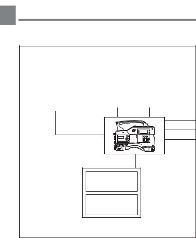
1-2 Example of System
Configuration
1
The diagram below shows a typical configuration of the camcorder for ENG and EFP. In this manual, the HDVF-20A HD Electronic Viewfinder (not supplied) is use to instruct how to operate the unit.
|
|
|
|
Viewfinder |
|
|
|
||||||
|
|
|
|
|
|
|
|
|
|
|
|
||
|
|
|
|
|
|
|
|
|
|
|
|
||
Viewfinder-related equipment |
|
|
HDVF-20A |
|
|
|
|
||||||
|
|
HD Electronic |
|
|
|
|
|||||||
|
|
|
|
|
|
|
|
|
|||||
|
|
|
|
|
|
||||||||
|
Fog-proof filter |
|
|
|
Viewfinder |
|
|
|
|
||||
|
(Part No. 1-547-341-11) |
|
|
|
|
|
|
|
|
|
|
|
|
|
|
|
|
|
|
|
|
|
|
|
|
|
|
|
|
|
|
|
HDVF-C30W |
|
|
Video monitor for |
|||||
|
|
|
|||||||||||
|
BKW-401 Viewfinder |
|
|
|
HD Electronic |
|
|
color image check |
|||||
|
|
|
|
Viewfinder |
|
|
while shooting |
||||||
|
Rotation Bracket |
|
|
|
|
|
|||||||
|
|
|
|
|
|
|
|
|
|
|
|
|
|
|
|
|
|
|
|
|
|
|
|
|
|
|
|
|
|
|
|
|
|
|
|
|
|
|
|
|
|
|
|
|
|
|
|
|
|
|
|
|
|
|
|
|
|
|
|
|
|
|
|
|
|
|
|
|
|
|
|
|
|
|
|
|
|
|
|
|
|
|
|
|
|
|
|
|
|
|
|
|
|
|
|
|
|
|
|
|
|
|
|
|
|
|
|
|
|
|
|
|
|
|
|
|
|
|
|
|
|
|
|
|
|
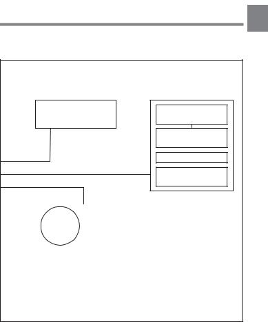
Remote control equipment
RCP-700 Series or
RM-B150 Remote
Control Unit
MSU-700A/750
Master Setup Unit
1-6 Chapter 1 Overview
1
For more information about the fittings, connections, or use of additional equipment and accessories, see Chapter 5 as well as the operation manuals for the connected equipment.
Camera adaptor
HDCA-901 for the input of the audio channels 3 and 4 and the HD-SDI output
Power source
|
|
|
|
|
|
Battery |
|||
|
AC power |
|
|
|
|
|
|||
|
|
|
|
|
|
||||
|
BC-L100 |
|
|||||||
|
supply |
|
|
||||||
|
|
Battery |
|
||||||
|
100V AC |
|
|
||||||
|
|
Charger |
|
||||||
|
|
|
|
|
|
|
|||
|
AC-550 |
|
|
BP-L60A |
|
||||
|
AC Adaptor |
|
|
Battery Pack |
|
||||
|
|
|
|
|
|
|
|
|
|
|
|
|
|
|
|
|
|
|
|
Audio signal source
External microphone C-74, etc.
CAC-12
Microphone Holder
Audio equipment
WRR-810A / 860A
UHF Portable Tuner
Chapter 1 Overview 1-7

1-3 Precautions
1 Use and Storage
Do not subject the camcorder to severe shocks
The internal mechanism may be damaged or the body warped.
After use
Always turn off the power.
Before storing the camcorder for a long period
Remove the battery pack.
Use and storage locations
Store in a level, ventilated place. Avoid using or storing the camcorder in the following places.
•Places subject to temperature extremes
•Very damp places
•Places subject to severe vibration
•Near strong magnetic fields
•In direct sunlight or close to heaters for extended periods
To prevent electromagnetic interference from portable communications devices
The use of portable telephones and other communications devices near this unit can result in misoperations and interference with audio and video signals.
It is recommended that the portable communications devices near this unit be powered off.
Note on laser beams
Laser beams may damage the CCDs. If you shoot a scene that includes a laser beam, be careful not to let a laser beam become directed into the lens of the camera.
1-8 Chapter 1 Overview
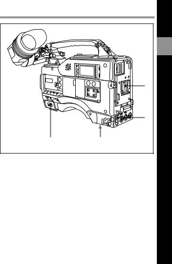
2-1 |
Power Supply |
|
|
|
1 |
|
|
2 |
|
4 |
3 |
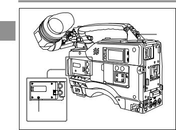
Power supply
1 Battery attachment
Attach a BP-L60A battery pack.
2 DC IN (external power input) connector (XLR type, 4-pin, male)
To operate the HDW-F900 using an AC power supply, connect an AC550 AC Adaptor with the DC output cable supplied with the adaptor. To use an external battery, connect its DC output cable to the DC IN connector.
(Continued)
Chapter 2 Locations and Functions of Parts and Controls |
2-1 |
2
Controls and Parts of Functions and Locations

3 BREAKER button
If excessive current flows within the unit, the breaker is tripped automatically to shut off the power supply and protect the equipment.
2 After performing internal checks or adjustments, use a pointed object such as a pen to press down lightly on this button. If there is no problem, the power will again be supplied.
4 POWER switch
This switch turns the main power supply on and off.
2-2 Chapter 2 Locations and Functions of Parts and Controls

2-2 |
Accessory Attachments |
|
|
1 |
2 |
|
|
2 |
|
|
3 |
|
|
4 |
|
|
5 |
|
|
6 |
|
|
7 |
|
8 |
Lens cable clamp |
|
|
|
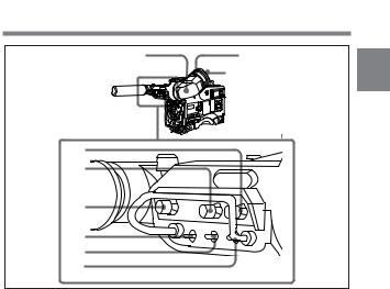
Accessory attachments
1 Shoulder strap posts
Attach the supplied shoulder strap to these posts.
2 Light shoe
Attach an optional accessory such as a video light to this shoe.
3 Lens mount (special bayonet mount)
Use this for mounting the lens.
(Continued)
Chapter 2 Locations and Functions of Parts and Controls |
2-3 |

4 Lens locking lever
After inserting the lens in the lens mount, rotate the lens mount ring with
this lever to lock the lens in position.
2
5 Lens mount cap
Remove this cap by pushing up on the lens locking lever. For protection from dust, always insert this cap when no lens is mounted.
6 Tripod mount
When using the unit on a tripod, attach the supplied tripod adaptor.
7 LENS connector (12-pin)
Fit the lens cable to this connector. Contact your Sony representative for more information about the lens you are using.
8 Shoulder pad
You can move the shoulder pad forwards or backwards by loosening the two screws. Do this to ensure the best balance when shooting with the camcorder on your shoulder.
2-4 Chapter 2 Locations and Functions of Parts and Controls
2-3 Audio Functions
1
2
2
3
Audio functions (1)
1 Microphone
This is a super-cardioid directional microphone with an external power supply (+48 V) system. You can use it as an interview microphone by connecting it to an extension cable (not supplied).
2 MIC IN (microphone input) connector (XLR type, 3-pin, female)
The supplied microphone connects to this connector. You can connect a microphone other than the supplied one as long as it corresponds to an external power supply system. The connector supplies power (+48 V) to the microphone.
3 MIC/MENU knob
This knob adjusts the audio level of the front microphone. To adjust the front microphone level, set the DISPLAY switch to ON, then push the MENU switch to CANCEL. The audio level indication will appear on the viewfinder screen. Note that you can do this only when the AUDIO SELECT switches are set to MANUAL and the AUDIO IN switches are
set to FRONT.
(Continued)
Chapter 2 Locations and Functions of Parts and Controls |
2-5 |

2 |
ADVANCE |
SHIFT |
CH-1 |
LEVEL |
CH-2 |
|
|
||||
• |
• • |
|
|
• • |
• |
|
|
||||
|
|
• |
• |
• |
• |
4 |
|||||
|
|
|
• |
|
|
• |
• |
|
|
• |
|
|
|
|
• |
|
|
• |
• |
|
|
• |
|
|
|
|
• |
|
• |
|
|
||||
|
PRESET |
|
0 |
•10 |
0 |
•10 |
|
||||
|
F-RUN |
|
|
|
|
|
|
|
|
||
|
|
|
SET |
|
|
AUTO |
|
|
|
5 |
|
|
|
|
|
|
|
|
|
|
|
||
|
|
R-RUN |
|
|
MANUAL |
|
|
|
|||
|
REGEN |
|
|
|
AUDIO SELECT |
|
|
|
|||
|
|
|
|
|
|
AUDIO IN |
|
|
|
|
|
|
|
DIAG |
REAL |
|
|
FRONT |
|
|
|
6 |
|
|
|
|
|
|
|
|
|
||||
|
|
|
TIME |
|
|
REAR |
|
|
|
||
|
DF |
|
ON |
|
|
|
|
|
|||
|
|
OFF |
|
|
CUE IN |
|
|
|
|
||
|
|
|
|
|
|
MIX |
|
|
|
|
7 |
|
NDF |
|
SET |
|
CH-1 |
|
|
CH-2 |
|
|
|
|
|
|
|
|
|
|
|
|
|
|
|
|
|
|
|
|
|
|
|
|
|
|
8 |
|
|
|
|
|
|
|
|
|
|
|
9 |
|
|
|
|
|
|
|
|
|
|
|
0 |
Audio functions (2)
2-6 Chapter 2 Locations and Functions of Parts and Controls

4LEVEL (CH-1/CH-2) (audio channel 1 and channel 2 recording level) controls
These controls adjust the audio levels of channels 1 and 2 when audio
input is from the AUDIO IN CH-1/CH-2 connectors and the AUDIO 2 SELECT switches are set to MANUAL.
5 AUDIO SELECT (CH-1/CH-2) (audio channel-1 and channel-2 adjustment method select) switches
These switches select the audio level adjustment method for each of audio channels 1 and 2.
AUTO: Select this setting for automatic adjustment. MANUAL: Select this setting for manual adjustment.
6 AUDIO IN (CH-1/CH-2) (audio input) switches
These switches select the audio input signals to be recorded for audio channels 1 and 2.
FRONT: The input signal source is the microphone connected to the MIC IN connector.
REAR: The input signal source is the audio equipment connected to the AUDIO IN CH-1/CH2 connectors.
You can also record audio signals in audio channels 3 and 4.
You can select the input signals to be recorded for audio channels 3 and 4 by using the AU REC CH 3/4 item on the VTR SETUP page of the MAINTENANCE menu.
The following three input signals are available:
1/2 CH: Records the same input signals connected to the AUDIO CH-1/ CH-2 connectors in audio channels 3 and 4..
AUTO: Records inputs signals other than the signals connected to the AUDIO CH-1/CH-2 connectors, that is signals which are not selected using the AUDIO IN switches.
This is effective only when the HDCA-901 camera adaptor is turned off, if connected.
For example: When the CH-1 of the AUDIO IN switch is set to FRONT: The audio signal input to the AUDIO IN CH-1 connector is recorded in
channel 3.
(Continued)
Chapter 2 Locations and Functions of Parts and Controls |
2-7 |

When CH-1 of the AUDIO IN switch is set to REAR:
The signal input to the MIC IN connector is recorded in channel 3. MUTE: Does not record any input signals in channels 3 and 4.
2 For more information, refer to the Maintenance Manual.
With the HDCA-901 (not supplied) connected to the camcorder, you can record separate sounds in audio channels 3 and 4.
7 CUE IN (cue track input) switch
This switch selects the input signal to be recorded on the cue track. CH-1: CH-1 input signal
MIX: Mixed input signals of CH-1 and CH-2 CH-2: CH-2 input signal
8 AUDIO OUT (audio output) connector (XLR type, 5-pin, male)
This connector outputs the audio signals recorded to audio channels 1 and 2 or audio channels 3 and 4.
The PB AUDIO CH item on the VTR SETUP page of the MAINTENANCE menu allows you to select the audio signal to be played back.
For more information, refer to the Maintenance Manual.
9AUDIO IN CH-1/CH-2 (audio channel 1 and channel 2 input) connectors (XLR type, 3-pin, female) and LINE/MIC/+48 V ON (line input/microphone input/external power supply +48 V ON)
switches
These are audio input connectors for channels 1 and 2 to which you can connect audio equipment or a microphone.
The LINE/MIC/+48V ON switches select the audio source of the audio input signals connected to each of these connectors.
LINE: Line input audio equipment
MIC: Microphone with an internal power supply
+48V ON: Microphone with an external power supply system
0 DC OUT (DC power output) connector
This connector supplies power for a WRR-810A/860A UHF Portable Tuner (not supplied). Do not connect any equipment other than the UHF portable tuner.
2-8 Chapter 2 Locations and Functions of Parts and Controls
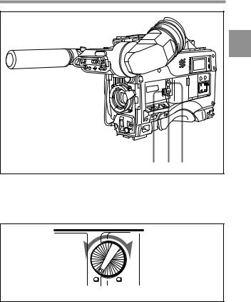
|
2 |
!£ |
!™ !¡ |
Audio functions (3)
qa ALARM volume control
This control adjusts the speaker or earphone alarm volume. At the minimum position, no sound can be heard.
Minimum Maximum
ALARM volume control
(Continued)
Chapter 2 Locations and Functions of Parts and Controls |
2-9 |

The internal volume control can be adjusted so that the alarm is audible even if the ALARLı olume control is at the minimum position.
For more information, refer to the Maintenance Manual.
2
qs MONITOR volume control
This control adjusts the speaker or earphone volume for sounds other than the alarm sound. At the minimum position, no sound can be heard.
MONITOR
CH-1
MIX
CH-2
Minimum Maximum
MONITOR volume control
qd MONITOR (audio channel select) switch
This switch selects the audio channel to be output from the speaker or earphone.
CH-1: Channel 1 audio
MIX: Mixed sound of channels 1 and 2 CH-2: Channel 2 audio
During playback, the signals of the audio channels selected from the PB AUDIO CH item on the VTR SETUP page of the MAINTENANCE manual are output.
2-10 Chapter 2 Locations and Functions of Parts and Controls
!¢ |
2 |
Audio functions (4)
qf Built-in speaker
During recording, the speaker can be used for monitoring the E-E1) sound, and during playback for monitoring playback sound. The speaker also sounds alarms to reinforce visual warnings.
If an earphone is plugged into to the EARPHONE jack, the speaker sound is automatically cut off.
See Section 6-3 “Operation Warnings” (page 6-14) for information about alarms.
....................................................................................................................................
1)E-E sound (Electric-to-Electric sound)
The term E-E sound refers to an audio signal that has passed though the amplifier, but has not been recorded on the tape. In other words, you can directly monitor the recording input signal, as opposed to the simultaneous playback (output) signal.
(Continued)
Chapter 2 Locations and Functions of Parts and Controls 2-11
2 |
qg |
|
qh |
Audio functions (5)
qg EARPHONE jack
You can monitor the E-E sound during recording and playback sound during playback. Plugging an earphone into the jack automatically cuts off the built-in speaker, and you hear the alarms about the camcorder's operation and status through the earphone.
qh Tap for measure hook
This is the hole for the M3 screw (effective screw length: 6mm) located at the position of the flange focal length. You can use this tap to attach the hook for a tape measure to measure the distance between the position of the flange focus and an object. (The effective length of the supplied screw is 6 mm.)
2-12 Chapter 2 Locations and Functions of Parts and Controls
2-4 Shooting and Recording/
Playback Functions
1 |
8 |
2 |
|
Eyecup |
|
|
|
2
3
4
5
6
7
Shooting and recording/playback functions (1)
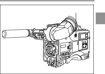
1 Viewfinder (When the HDVF-20A (not supplied) is used)
The viewfinder lets you to view the camera image in black and white while shooting the picture and also see the playback picture from the VTR. It also displays various warnings and messages related to the settings or operating conditions of the camcorder, a zebra pattern1), safety zone marker2), and center marker3).
....................................................................................................................................
1)Zebra pattern
The zebra pattern aids in manual iris adjustment by indicating areas of the picture where the video level is approximately 70% and 100% and above.
2)Safety zone marker
The safety zone marker is a rectangle indicating the effective picture area.
For more information, see Section 4-8-3 “Setting the Marker Display” (page 4-55).
3)Center marker
The center marker indicates the center of the picture with a crosshair.
(Continued)
Chapter 2 Locations and Functions of Parts and Controls 2-13

2 BRIGHT (brightness) control
This control adjusts the picture brightness on the viewfinder screen. It has no effect on the camera output signal.
2 3 CONTRAST control
This control adjusts the picture contrast on the viewfinder screen. It has no effect on the camera output signal.
4 PEAKING control
This control adjusts the sharpness of the picture on the viewfinder screen to make focusing easier. It has no effect on the camera output signal.
5 DISPLAY/ASPECT (display/aspect control)switch
Use this switch to turn the markers and aspect mask function on or off. DISPLAY: When MARKER on the MARKER page of the
OPERATION menu is set to ON, pushing this switch to DISPLAY toggles the markers on the viewfinder screen on and off.
ASPECT: When MASK on the MARKER page of the OPERATION menu is set to ON, pushing this switch to the aspect mask function toggles on and off.
6 ZEBRA (zebra pattern) switch
This switch controls the zebra pattern on the viewfinder screen. ON: The zebra pattern is displayed and stays.
2-14 Chapter 2 Locations and Functions of Parts and Controls
Loading...