


OLED VIEWFINDER
HDVF-EL30 HDVF-EL20
OPERATION MANUAL [English] 1st Edition

Table of Contents |
|
Precautions................................................ |
3 |
Overview .................................................... |
4 |
Functions of Parts and Controls.............. |
6 |
Front panel ................................................. |
7 |
Indicators on the screen ............................. |
8 |
Attaching to the Camera........................... |
9 |
Adjusting Focus and Screen.................. |
10 |
Adjusting the Focus ................................. |
10 |
Adjusting the Screen................................ |
10 |
Attaching Accessories............................ |
11 |
Attaching the hood |
|
(HDVF-EL30 only) ........................ |
11 |
Attaching a Microphone .......................... |
12 |
About the eye sensor.............................. |
12 |
Switching the eye point .......................... |
13 |
Adjusting the LCD monitor |
|
(HDVF-EL30 only) ........................... |
13 |
Adjusting the angle .................................. |
13 |
Adjusting the screen................................. |
13 |
Using the LCD monitor as the tally ......... |
13 |
Using the Focus Assist Function .......... |
14 |
COLOR PEAKING Function .................. |
14 |
PEAKING PLUS Function...................... |
14 |
MAGNIFICATION Function .................. |
16 |
Using the Menu........................................ |
17 |
Basic Menu Operations............................ |
17 |
List of Menu Items................................... |
19 |
Error Message ......................................... |
23 |
Specifications.......................................... |
23 |
2 |
Table of Contents |
|
|

Precautions
Viewfinder Lenses
Do not leave the viewfinder lens faced toward a strong light source, such as sunlight.
A concentration of strong light, such as sunlight via the lens may burn out the OLED panel or cause a fire.
About the OLED panel
The OLED panel fitted to this unit is manufactured with high precision technology, giving a functioning pixel ratio of at least 99.99%. Thus a very small proportion of pixels may be “stuck”, either always off (black), always on (red, green, or blue), or flashing. In addition, over a long period of use, because of the physical characteristics of the organic light-emitting diode, such “stuck” pixels may appear spontaneously. These problems are not a malfunction.
These phenomena have no effect on the camera’s output signals.
Burn-in
Due to the characteristics of the material used in the OLED panel, permanent burn-in or reduction in brightness may occur.
These problems are not a malfunction.
When still images are displayed in the same position on the screen continuously or repeatedly, permanent burn-in may occur.
Images that may cause burn-in
•Character or message displays that indicate settings or the operating state
•On-screen displays such as center markers or safety zones
•Masked images with aspect ratios other than 16:9
•Color bars or images that remain static for a long time
•When the HIGH EYEPOINT function is set to “ON.”
To reduce the risk of burn-in
•Use with the EYE SENSOR setting set to “ON” This unit has an anti-burn-in function for the OLED panel.
When your eye is away from the eyecup, an image with the video signal level reversed may be displayed or the image may be not displayed.
•Fill the entire screen with images
-Displays the image after switching HIGH EYEPOINT to “OFF.”
-Turn the mask display of the connected camera to “OFF” before displaying the image. For details, refer to the operation manual of the camera.
•Turn off the character and marker displays Press the MENU switch to turn off the character
displays. To turn off the character or marker displays of the connected equipment, operate the connected equipment accordingly. For details, refer to the operation manual of the connected equipment.
•Turn off the power when not in use
Turn off the power if the viewfinder is not to be used for a prolonged period of time.
About the LCD panel (HDVF-EL30 only)
•The LCD panel fitted to this unit is manufactured with high precision technology, giving a functioning pixel ratio of at least 99.99%. Thus a very small proportion of pixels may be “stuck”, either always off (black), always on (red, green, or blue), or flashing. In addition, over a long period of use, because of the physical characteristics of the liquid crystal display, such “stuck” pixels may appear spontaneously. These problems are not a malfunction.
These phenomena have no effect on the camera’s output signals.
•Do not leave the screen facing the sun as it can damage the screen. Take care when you use the unit outdoors.
•Do not push or scratch the screen. Do not place a heavy object on the screen. This may cause the screen to lose uniformity.
•An afterimage may appear when a still image is displayed continuously. Turn the viewfinder off when it is not used for a long time.
•When using the viewfinder in low temperature, the moving image resolution deteriorates right after the viewfinder is turned on.
Handling and maintenance of the screen
The surface of the screen is specially coated to reduce image reflection. Make sure to observe the following points as improper maintenance procedures may impair the screen’s performance. In addition, the screen is vulnerable to damage. Do not scratch or knock against it using a hard object.
•Be sure to turn off the power of the connected equipment before performing maintenance.
•The surface of the screen is specially coated. Do not attach adhesive objects, such as stickers, on it.
•The surface of the screen is specially coated. Do not touch the screen directly.
•Wipe the screen surface gently with a soft dry cloth to remove dirt.
•Stubborn stains may be removed with a soft cloth slightly dampened with a mild detergent solution.
•The screen may become scratched if a cloth is dusty.
•Never use strong solvents such as alcohol, benzene, thinner, acidic or alkaline detergent, detergent with abrasives, or chemical wipe as these may damage the screen.
Precautions 3

• Use a blower to remove dust from the screen surface.
Do not subject the screen to strong impact
Strong impact on the screen may damage it, such as deformation of the internal structure or outer appearance.
Electrolytic capacitor
The life expectancy of the electrolytic capacitor is about 5 years under normal operating temperatures and normal usage (8 hours per day; 25 days per month). If usage exceeds the above normal usage frequency, the life expectancy may be reduced correspondingly.
Operation and storage environment
Store the viewfinder in a level and air-conditioned place. Avoid using or storing in the following places:
•Places that are extremely hot or cold
•Places with a high level of humidity
•Places with strong vibrations
•Places with strong magnetic fields
•Places that are exposed to direct sunlight for long hours or near a heating device
Dew condensation
If the unit is suddenly taken from a cold to a warm location, or if ambient temperature suddenly rises, moisture may form on the outer surface of the unit and/or inside of the unit. This is known as condensation. If condensation occurs, turn off the unit and wait until the condensation clears before operating the unit. Operating the unit while condensation is present may damage the unit.
Disposal of the unit
Do not dispose of the unit with general waste. Do not include the unit with household waste.
When you dispose of the unit, you must obey the law in the relative area or country.
Overview
The HDVF-EL30/HDVF-EL20 OLED Viewfinder is a color viewfinder for use with a Sony high-definition color camera.
This viewfinder has the following features.
Advantages of OLED panel technology
The OLED panel makes use of an organic material, which emits light when an electric current is applied. Being selfemitting, the strength of luminescence can be controlled by the amount of electric current. This brings about the following three features:
Quick motion picture response:
The luminescent state of the OLED panel can be changed instantaneously by changing the current flow in the organic material. This enables a quick motion picture response and production of images with minimal blurring and ghosting. Furthermore, performance for shooting on location is not influenced by changes in environmental temperature.
High contrast and wide dynamic range:
The OLED panel does not emit light when black signal is applied to the viewfinder, enabling a pure black screen to be displayed. Furthermore, thanks to high peak brightness the panel impressively displays brilliance and clarity of various sparkling images, such as stars in a night sky twinkling, night illuminations winking or glass glittering, etc.
Rich color reproduction:
An OLED panel’s self-luminescence also allows for great color reproduction across the entire spectrum in practically any shade or brightness.
Focus Assist function
This viewfinder comes with an original Focus Assist function to support accurate focusing.
•Peaking function
Edge enhancement can be performed in the horizontal/ vertical direction on the entire of the screen. Coloring the edge enhancement part can improve visibility.
•Peaking Plus function
Edge enhancement can be performed on the object that is specified using a color, area selected, or both.
•Image magnification (FOCUS MAG) function Displays a part of the image expanded to twice the size. You can adjust the focus easily.
To switch to preset adjustment settings
Brightness and contrast can be preset for selection through an assignable switch or a menu operation.
4 Overview

Assignable switch
Two assignable switches are provided for the storage of frequently used functions.
Tally lamps
The viewfinder comes with three tally lamps (red, green, and yellow), which light up in response to tally signals. Check the connected camera to identify whether the use of the yellow tally lamp is supported.
You can use the LCD screen as an up-tally. (HDVF-EL30 only)
High-performance loupe
The 4-group 7-element lens (including aspheric lens) delivers pictures with low distortion and allows adjustment over a wide range of visibility.
If the optional close-up lens (ø37) is mounted, you can shift the visibility ratio to the far-sighted side.
Hood for the LCD panel (HDVF-EL30 only)
A small, light hood for the LCD panel is supplied. This is useful when recording.
Overview 5

Functions of Parts and Controls
HDVF-EL30
|
Viewfinder cable |
|
Microphone |
LCD (HDVF-EL30 only) |
|
holder |
||
|
Front panel (page 7)
HDVF-EL20
Viewfinder cable 
Microphone holder
Front panel (page 7)
6 |
Functions of Parts and Controls |
|
|
aPlug
Connect to the VF connector on the camera.
bStopper
Prevents the viewfinder from coming off the camera when it is slid from side to side.
cTally indicator (front)
Lights up when the camera receives the red tally signal. The brightness can be adjusted with the TALLY switch on the front panel. Set the TALLY switch to OFF when not in use.
dMENU control
Turn the control to select a menu item, and then press the control to confirm the selection. Use with the MENU switch to set various functions.
When the menu is not displayed, pressing this control shows the status information of the viewfinder on the screen.
For details on operations, see “Using the Menu” on page 17.
eTally indicator (rear)
Lights up when the camera receives the red tally signal. This indicator can be covered when not in use.
fEyecup
Blocks external light while you are shooting.
Over time the eyecup may become cracked. If this occurs, it should be exchanged.
gEye sensor
Controls the anti-burn-in function for the OLED panel.
Notes
•Do not cover or block the eye sensor.
•To prevent screen burn-in on the OLED panel, the video signal level in the display may be inverted or the image may not be displayed when your eye is not in contact with the eyecup.
hDiopter adjustment ring
Turn this until the image is sharpest for your eyesight.
iASSIGN (assignable) 1/2 switches
Can be used to store frequently used functions. Storing a function is performed using “ASSIGN 1” or “ASSIGN 2” in the FUNCTION menu (page 19).
jMENU switch
Displays the menu. Use with the MENU control to set various functions.
When the menu is not displayed and this switch is pressed and held for three seconds or more, “VR LOCK” appears. This locks the BRIGHT, CONTRAST, and PEAKING controls at their current settings, preventing accidental operation. To unlock the controls, press this switch for three seconds or more again so that “VR UNLOCK” appears.
For details on operations, see “Using the Menu” on page 17.
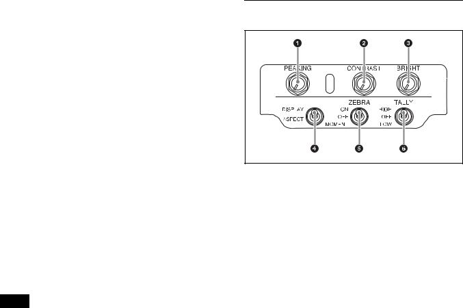
Front panel
aPEAKING control
Sharpens the edges in the picture. This control has no effect on the camera’s video output signals. Turning the control clockwise increases the sharpness.
bCONTRAST control
Adjusts the picture contrast. This control has no effect on the camera’s video output signals. Turning the control clockwise increases the contrast.
HDVF-EL20
This control is disabled when “PRESET” in the PRESET menu (page 21) is set to “ON.”
HDVF-EL30
This control is disable when “PRESET” is set to “ON” and “PRESET SELECT” is set to “BOTH” in the PRESET menu (page 21).
cBRIGHT (brightness) control
Adjusts the picture brightness. This control has no effect on the camera’s video output signals. Turning the control clockwise increases the brightness.
HDVF-EL20
This control is disabled when “PRESET” in the PRESET menu (page 21) is set to “ON.”
HDVF-EL30
This control is disable when “PRESET” is set to “ON” and “PRESET SELECT” is set to “BOTH” in the PRESET menu (page 21).
Functions of Parts and Controls |
7 |
|
|

dASPECT/DISPLAY switch
Switches the image display ratio and DISPLAY indication/marker indication ON/OFF.
ASPECT: Each push of the switch to this position toggles the mask display on and off.
DISPLAY: Switches the DISPLAY indication ON/OFF and switches the marker indication ON/OFF when the camera's marker indication is set to “ON.”
Note
The motion differs while operating the DISPLAY switch depending on the connecting camera.
eZEBRA (zebra pattern) switch
Controls the zebra pattern display on the viewfinder screen as follows:
ON: A zebra pattern appears and stays. OFF: The zebra pattern disappears.
MOMENT: A zebra pattern appears and stays for about 5 seconds.
fTALLY switch
Controls the TALLY indicator (page 7) located on the front of the viewfinder.
HIGH: The tally indicator brightness is set to high. OFF: The tally indicator is disabled.
LOW: The tally indicator brightness is set to low.
Indicators on the screen
Indicators are located on the upper and lower and left and right parts of the OLED and LCD screen (HDVF-EL30 only) to indicate the status of the camera or this unit.
aPEAKING PLUS indicator (blue)
Operates the ASSIGN switch assigned with the PEAKING PLUS function or lights up when “PEAKING MODE” in the PEAKING PLUS menu (page 20) is set to “PLUS.”
bMAG (magnification) position indicator
Shows the expanded display among the center / upper / right / lower / left parts of the screen.
cG TALLY indicator (green)
Lights up when the green tally signal is input.
dR TALLY indicator (red)
Lights up when the red tally signal is input.
eY TALLY indicator (yellow)
Lights up when the yellow tally signal is input.
fBATT (battery) indicator (red)
Lights up or flashes, to indicate the status of the battery attached to the camera as follows.
Lit: The battery is drained.
Flashing: The voltage of the battery has dropped below the threshold value.
To prevent camera from shutting down, change the battery as soon as possible after this indicator begins flashing.
The threshold battery voltage value at which this indicator begins lighting up or flashing can be set by the camera. For details, refer to the manual for the camera.
gSTATUS indicator (amber)
Shows the current status of the viewfinder.
Blinking in intervals of 0.5 seconds: A problem is detected during self-diagnosis. An error message (see page 23) may be displayed at the same time. Turn off the power and contact your Sony service representative.
h

 (attention) indicator (amber)
Lights up when the camera detects certain conditions. The conditions under which the indicator lights up are specified on the camera.
For details on how to set up and verify the conditions under which the 

 indicator lights up, refer to the manual of the camera in use.
iSAVE indicator (amber)
Lights when the recorder attached to the camera is in power save mode.
jMAG (magnification) indicator (amber)
Lights up when the displayed image is magnified (when the ASSIGN switch of the MAGNIFICATION function is set to “ON,” or “MAGNIFICATION” in the MAGNIFICATION menu (page 21) is set to “ON”).
8 |
Functions of Parts and Controls |
|
|
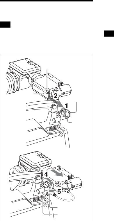
Attaching to the Camera
Note
When the viewfinder is attached, do not leave the camera with the eyepiece facing the sun. Direct sunlight can enter through the eyepiece and be focused in the viewfinder, which may cause the OLED panel to burn out or cause a fire.
Stopper |
Slide rail |
Slide guide |
Left-right |
positioning |
ring |
Plug |
VF connector |
1 Loosen the left-right positioning ring on the camera.
2 Insert the slide guide which is located on the front of the camera into the slide rail which is located on the back of the viewfinder.
3 Slide the viewfinder in the direction of the arrow.
4 Position the viewfinder by sliding it from side to side, and tighten the left-right positioning ring on the camera.
5 Connect the plug to the VF connector on the camera.
Note
Always check to be sure that the plug is firmly inserted into the camera’s VF connector.
To detach the viewfinder
To detach the viewfinder from the camera, conduct the attachment procedure in reverse. When removing the viewfinder from the camera, pull up the stopper.
Note about loading in carrying case
When loading the camera with viewfinder attached into a carrying case, make sure that the camera and the viewfinder fit into the case without having to be forced. Applying undue pressure can result in damage to the camera or viewfinder.
Attaching to the Camera |
9 |
|
|
 Loading...