


SONY
HD CAMCORDER
HDW-700A
HDCAM
OPERATION MANUAL English 1st Edition
Serial No. 10001 and Higher

WARNING
To prevent fire or shock hazard, do not expose the unit to rain or moisture.
To avoid electrical shock, do not open
the cabinet. Refer servicing to qualified personnel only.
For the customers in U.S.A
This equipment has been tested and found to comply with the limits for a Class A digital device, pursuant to Part 15 of theFCC Rules. These limits are designed to provide reasonable protection against harmful interference when the equipment is operated in a commercial environment. This equipment generates, uses, and can radiate radio frequency energy and, if not installed and used in accordance with the instruction manual, may cause harmful interference to radio communications. Operation of this equipment in a residential area is likely to cause harmful interference in which case the user will be required to correct the interference at his own expense.
You are cautioned that any changes or modifications not expressly approved in this manual could void your authority to operate this equipment.
The shielded interface cable recommended in this manual must be used with this equipment in order to comply with the limits for a digital device pursuant to Subpart B of Part 15 of FCC Rules.

For the customers in the USA and Canada
RECYCLING NICKEL-CADMIUM BATTERIES
|
NICKEL-CADMIUM BATTERY. |
|
BATTERY MUST BE RECYCLED OR |
|
DISPOSED OF PROPERLY. |
Ni-Cd |
Nickel-Cadmium batteries are recyclable. |
You can help preserve our environment by |
|
|
returning your unwanted batteries to your |
|
nearest Sony Service Centre or Factory |
|
Service Centre for collection, recycling or |
|
proper disposal. |
|
Note: In some areas the disposal of nickel - |
|
cadmium batteries in household or business |
|
trash may be prohibited. |
For the Sony Service Centre nearest you call 1-800-222-
SONY (United States only)
For the Sony Service Centre nearest you call 416-499-
SONY (Canada only)
Caution: Do not handle damaged or leaking nickel-cadmium batteries.

Table of Contents
Chapter 1 Overview
1-1 |
Features....................................................................................... |
1-1 |
|
1-1-1 Camera Features................................................................ |
1-1 |
|
1-1-2 VTR Features..................................................................... |
1-3 |
1-2 |
Example of System Configuration........................................ |
1-4 |
1-3 |
Precautions................................................................................ |
1-6 |
Chapter 2 Locations and Functions of Parts and
Controls
2-1 |
Power Supply............................................................................... |
2-1 |
2-2 |
Accessory Attachments.............................................................. |
2-3 |
2-3 |
Audio Functions.......................................................................... |
2-5 |
2-4 Shooting and Recording/Playback Functions........................ |
2-13 |
|
2-5 Setup Menu Operating Section................................................ |
2-27 |
|
2-6 Time Code System...................................................................... |
2-29 |
|
2-7 Warnings and Indications.......................................................... |
2-35 |
|
2-8 |
Warnings and Indications on the Display Panel..................... |
2-38 |
Chapter 3 Recording and Playback
3-1 |
About Cassettes......................................................................... |
3-1 |
|
|
3-1-1 |
Loading and Unloading a Cassette................................ |
3-1 |
|
3-1-2 |
Preventing Accidental Erasure...................................... |
3-4 |
3-2 |
Recording................................................................................... |
3-5 |
|
|
3-2-1 |
Basic Procedure.............................................................. |
3-5 |
|
3-2-2 |
Continuous Recording................................................... |
3-9 |
3-3 |
Checking the Recording – Playback...................................... |
3-12 |
|
|
3-3-1 Checking the last Three Seconds of the Recording – |
|
|
|
|
Recording Review..................................................... |
3-12 |
|
3-3-2 Checking the Recording on the Color Video Monitor – |
||
|
|
Playback in Color....................................................... |
3-13 |
Table of Contents |
1 |

Chapter 4 |
Adjustments and Settings for |
|
|
Recording |
|
4-1 Adjusting the Black Balance and the White Balance and |
|
|
Correcting the White Spots................................................... |
4-1 |
|
4-1-1 Adjusting the Black Balance....................................... |
4-2 |
|
4-1-2 Automatic Correction of White Spots in the Image.... |
4-4 |
|
4-1-3 Adjusting the White Balance......................................... |
4-5 |
|
4-2 Setting the Electronic Shutter............................................... |
4-9 |
|
4-2-1 |
Shutter Modes................................................................ |
4-9 |
4-2-2 Selecting the Shutter Mode and Speed.......................... |
4-10 |
|
4-3 Adjusting the Audio Level..................................................... |
4-13 |
|
4-4 Setting the Time Data........................................................... |
4-17 |
|
4-4-1 Setting the User Bits.................................................... |
4-17 |
|
4-4-2 Setting the Time Code.................................................. |
4-19 |
|
4-4-3 Entering the Real Time in the VITC............................. |
4-21 |
|
4-4-4 Synchronizing the Time Code...................................... |
4-23 |
|
4-5 Setup Menu Display on the Viewfinder Screen................. |
4-28 |
|
4-5-1 Basic Use of the Setup Menu..................................... |
4-31 |
|
4-6 Status Display on the Viewfinder Screen |
4-34 |
|
4-6-1 Layout of the Status Display on the Viewfinder Screen |
4-34 |
|
4-7 Setup Using the OPERATION Menu.......................... |
4-38 |
|
4-7-1 Finding a Page.............................................................. |
4-39 |
|
4-7-2 Selecting the Items for Which the “!” LED is to Light. 4-40 |
||
4-7-3 Setting the Marker Display.......................................... |
4-42 |
|
4-7-4 Selecting the Display Items.......................................... |
4-43 |
|
4-7-5 Setting the GAIN Selector Values................................. |
4-45 |
|
4-7-6 |
Setting the Viewfinder................................................... |
4-47 |
4-7-7 Setting the Automatic Iris.............................................. |
4-48 |
|
4-7-8 Setting the Battery, D5600K Mode and Selecting the Lens |
||
|
File................................................................................. |
4-50 |
4-7-9 |
Operator File................................................................. |
4-52 |
4-8 Paint Menu........................................................................... |
4-54 |
|
2 Table of Contents

4-9 Using the Setup Card.............................................................. |
4-64 |
|
4-9-1 |
Handling the Setup Card............................................. |
4-64 |
4-9-2 |
Using Data on the Setup Card.................................... |
4-66 |
Chapter 5 |
Setting Up The Camcorder |
|
||
5-1 |
Power Supply............................................................................ |
5-1 |
||
|
5-1-1 Using a BP-L60A/L90A Battery Pack.......................... |
5-1 |
||
|
5-1-2 Using a BP-90A Battery Pack........................................ |
5-4 |
||
|
5-1-3 Avoiding Breaks in Operation Due to Dead Batteries... |
5-5 |
||
|
5-1-4 |
Using anACAdaptor..................................................... |
5-6 |
|
|
5-1-5 Using the Anton Bauer Ultralight System.................... |
5-7 |
||
5-2 |
Adjusting the Viewfinder......................................................... |
5-8 |
||
|
5-2-1 Adjusting the Viewfinder Position.............................. |
5-8 |
||
|
5-2-2 |
Detaching the Viewfinder............................................... |
5-10 |
|
5-3 Mounting the Lens..................................................................... |
5-12 |
|||
5-4 Adjusting the Flange Focal Length......................................... |
5-13 |
|||
5-5 Audio Input System .................................................................. |
5-15 |
|||
|
5-5-1 Using the Supplied Microphone.................................... |
5-15 |
||
|
5-5-2 Using an External Microphone...................................... |
5-18 |
||
|
5-5-3 Attaching a UHF Portable Tuner (for a UHF Wireless |
|
||
|
|
|
Microphone System)..................................................... |
5-23 |
|
5-5-4 Connecting Line Input Audio Equipment...................... |
5-27 |
||
5-6 |
Tripod Mounting........................................................................ |
5-28 |
||
5-7 Attaching the Shoulder Strap.................................................. |
5-30 |
|||
5-8 Adjusting the Shoulder Pad Position...................................... |
5-32 |
|||
5-9 Putting On the Rain Cover...................................................... |
5-33 |
|||
5-10 Connecting the Remote Control Unit................................... |
5-36 |
|||
Table of Contents |
3 |

Chapter 6 |
Maintenance |
|
|
6-1 Testing the Camcorder Before Shooting............................. |
6-1 |
||
|
6-1-1 |
Preparations for Testing............................................... |
6-1 |
|
6-1-2 Testing the Camera........................................................ |
6-2 |
|
|
6-1-3 |
Testing the VTR............................................................. |
6-6 |
6-2 |
Maintenance........................................................................... |
6-10 |
|
|
6-2-1 Cleaning the Video Heads............................................ |
6-10 |
|
|
6-2-2 |
Cleaning the Viewfinder............................................... |
6-10 |
6-3 |
Operation Warnings.............................................................. |
6-12 |
|
|
|
|
|
Appendix |
|
|
|
Specifications........................................................................................ |
A-1 |
||
|
Video Camera Section............................................................... |
A-2 |
|
|
VTR Section.............................................................................. |
A-3 |
|
|
Supplied Accessories................................................................. |
A-6 |
|
|
Recommended Additional Equipment....................................... |
A-6 |
|
Glossary.................................................................................................. |
|
A-9 |
|
Index........................................................................................................ |
|
|
1-1 |
4 |
Table of Contents |

1-1 Features
The HDW –700A HD Camcorder combines a HD color video camera, of |
1 |
which effective picture elements is 1920(H) x 1080(V) and which uses |
2/3 inch FIT1) CCD2) imagers with 2,000,000 picture elements, with an HDCAM portable videocassette recorder. Its excellent portability and dustand water-proof construction make it ideal as a camcorder for ENG3) and EFP4) in the same way as the earlier DVW-700, which is the Digital BETACAM model. The introduction of a new method of processing HD digital signals improves the image quality even further and simplifies setup (initialization) operations.
1-1-1 Camera Features
The features of the HDW-700A camera are described below.
•2/3 inch FIT CCDs with 2,000,000 picture elements provide a compact and lightweight unit with excellent image quality.
•Existing 2/3 inch lenses can be used.
•Digital signal processing has improved picture quality, stability, and reliability.
•A setup menu enables you to control features such as status displays, messages, and markers; to select various types of settings; to toggle switches; and to operate a setup card.
•Blur-free shooting is ensured by a built-in, high-performance electronic shutter that provides a variety of modes, such as ECS5) mode which reduces flickering on the monitor screen and S-EVS6) mode which improves vertical resolution.
•Selectable video gain ensures a noise-free image.
•A simple switch operation enables automatic adjustment of the black set, black balance, and white balance. Memory functions make it easy to replicate the white balance setting appropriate for the lighting conditions.
1)FIT: Frame Interline Transfer
2)CCD: Charge-Coupled Device
3)ENG: Electronic News Gathering
4)EFP: Electronic Field Production
5)ECS: Extended Clear Scan
6)S-EVS: Super Enhanced Vertical definition System
Chapter 1 Overview |
1-1 |

1 • Character display functions on the viewfinder indicate switch settings, automatic black and white balance adjustment, status indications, and warnings.
•The warning system uses various types of warning indicators and sounds to inform you of VTR faults, end of tape, low battery, etc.
•The camcorder is equipped with a dual-wheel filter disk for adjusting the filter setting to shooting and lighting conditions.
•Override function which makes fine adjustment of the reference value for brightness of automatic iris control is provided.
•A built-in circuit produces a color bar signal for easy adjustment of the color monitor.
•The remote control unit controls camera functions and VTR functions.
•Setup data specified by the camera operator, including the various marker settings, can be stored in the camcorder itself or on a setup card as an operator file, and then can be recalled.
•Setup data specified by video engineers, including the various detail settings, can be stored in the camcorder itself and on a setup card as a reference file, and then can be recalled. It is possible to shorten time for setting with duplicating the stored reference file to the other cameras through the setup card,
•Setup data specified by video engineers, including the video settings, can be stored as a scene file. It is possible to recall the setup data appropriate for the scene.
•Correction value to use a lens extender and for each lens can be stored as a lens file, and then can be recalled. It is possible to shorten time for adjustment when replacing the lens.
•Ahigh-performance viewfinder is adjustable forward, backward, and sideways, and has a full range of auxiliary equipment.
1-2 Chapter 1 Overview
|
|
|
|
|
1 |
1-1-2 VTR Features |
|
|
|
|
|
The VTR features of this camcorder are described below.
•Use of the HDCAM format allows high performance HD digital recording and playback while preserving the same ease of use as conventional camcorder equipment.
•The same cassette size (S size) as Digital BETACAM can be used to achieve a long recording time of approximately 40 minutes.
•The recording review function, which automatically rewinds and plays back the last approximately 3 seconds of recording on the tape, enables
you to quickly confirm recorded contents.
•No playback adaptor is needed to see the color playback image on the monitor screen.
•The 3 times normal speed search function provides quick positioning of the tape.
•LTC1) and VITC2) recording and LTC playback can be performed.
•The built-in time code generator can be synchronized with an external generator.
•Alithium battery is the back-up power supply for the built-in time code generator enabling the time code to be held for approximately 5 years without charging the camcorder power supply.
•Optional long-life battery packs are available.
•Pressing the VTR START button on the camcorder or the VTR button on the lens ensures recording continuity from the very next frame.
•Two analog audio input channels can be recorded as 16-bit digital signals.
1)LTC: LongitudinalTime Code
2)VITC: Vertical Interval Time Code
Chapter 1 Overview |
1-3 |
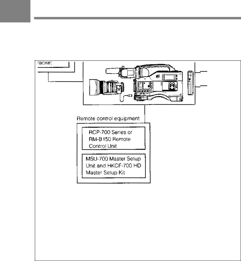
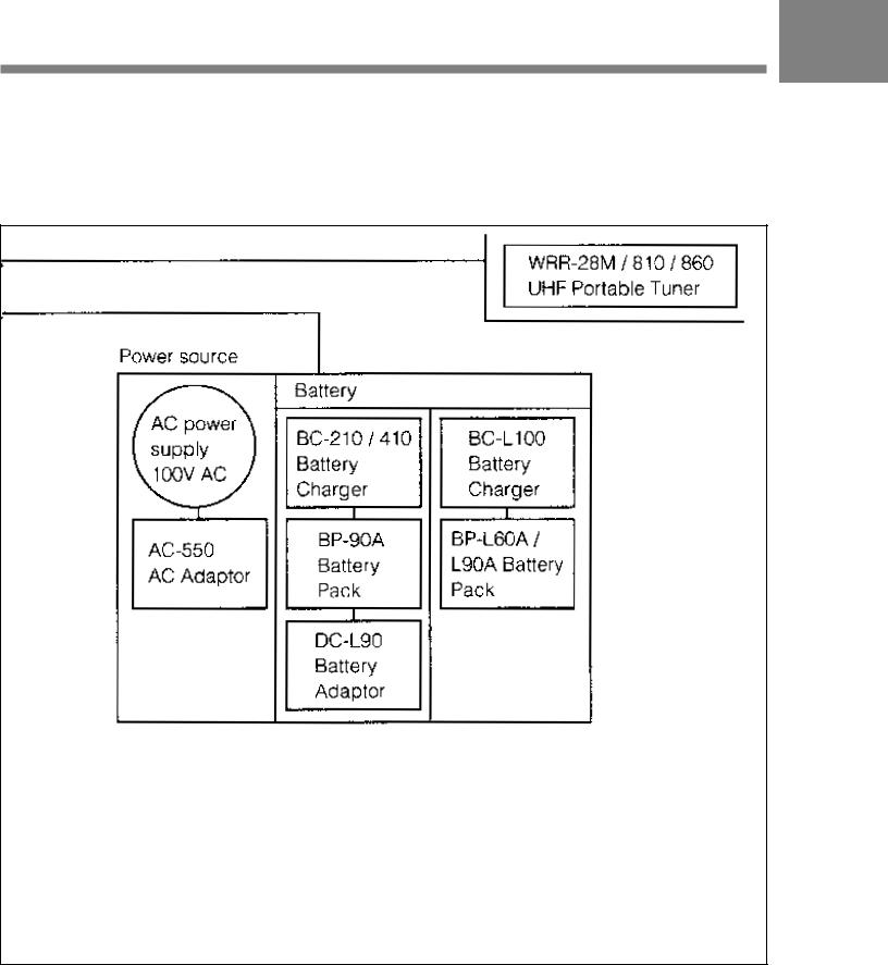
1-2 Example of System
1 Configuration
The diagram below shows a typical configuration of the camcorder for ENG and EFP.
For more information about the fittings, connections, or use of additional equipment and accessories, see Chapter 5 as well as the operation manuals for the connected equipment.
1- 4 Chapter 1 Overview
1
Chapter 1 Overview |
1-5 |

1-3 Precautions
1 Use and Storage
Do not subject the camcorder to severe shocks
The internal mechanism may be damaged or the body warped.
After use
Always turn off the power.
Before storing the camcorder for a long period
Remove the battery pack.
Use and storage locations
Store in a level, ventilated place. Avoid using or storing the camcorder in the following places.
•Places subject to temperature extremes
•Very damp places
•Places subject to severe vibration
•Near strong magnetic fields
•In direct sunlight or close to heaters for extended periods
1-6 Chapter 1 Overview
2-1 Power Supply
2
Power Supply
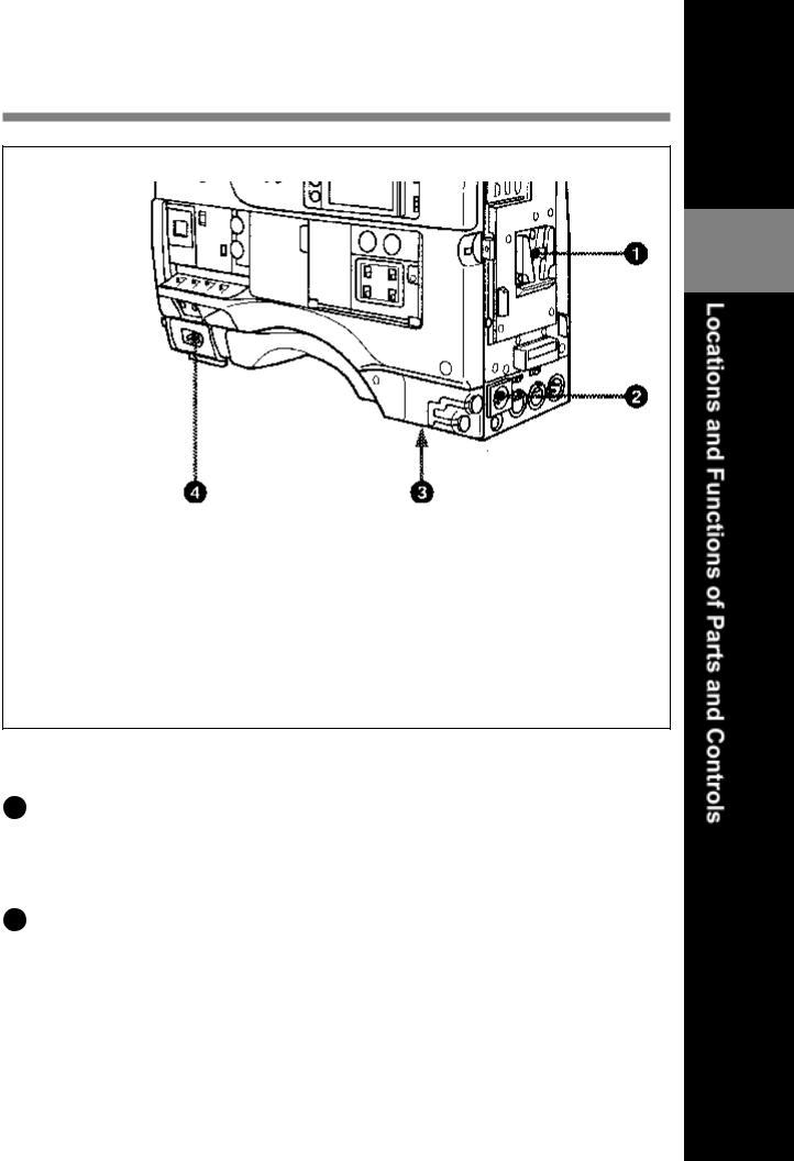
1 Battery attachment
Attach a BP-L60A/L90Abattery pack. A DC-L90 Battery Adaptor for loading a BP-90A Battery Pack also can be attached.
2 DC IN (external power input) connector (XLR type, 4-pin, male)
To operate the HDW-700A using anAC power supply, connect anAC550 AC Adaptor with the DC output cable supplied with the adaptor. To use an external battery, connect its DC output cable to the DC IN connector.
Chapter 2 Location and Functions of Parts and Controls |
2-1 |

|
3 BREAKER button |
|
If excessive current flows within the unit, the breaker is tripped |
2 |
automatically to shut off the power supply and protect the equipment. |
After performing internal checks or adjustments, use a pointed object |
|
such as a pen to press down lightly on this button. If there is no problem, |
the power will again be supplied.
.4 POWER switch
This switch turns the main power supply on and off.
2-2 Chapter 2 Locations and Functions of Parts and Controls

2-2 Accessory Attachments
2
Accessory attachments
1 Shoulder strap posts
Attach the supplied shoulder strap to these posts.
2 Light Shoe
Attach an optional accessory such as a video light to this shoe.
3 Lens mount (special bayonet mount)
Use this for mounting the lens.
Chapter 2 Locations and Functions of Parts and Controls |
2-3 |

|
4 |
Lens locking lever |
|
|
After inserting the lens in the lens mount, rotate the lens mount ring with |
||
|
this lever to lock the lens in position. |
||
2 |
|||
5 |
Lens mount cap |
||
|
Remove this cap by pushing up on the lens locking lever. For protection |
||
|
|||
|
from dust, always insert this cap when no lens is mounted. |
||
|
6 |
Tripod mount |
|
|
When using the unit on a tripod, attach the supplied tripod adaptor. |
||
|
7 |
LENS connector (12-pin) |
|
|
Fit the lens cable to this connector. Contact your Sony representative for |
||
|
more information about the lens you are using. |
||
|
8 |
Shoulder pad |
|
|
You can move the shoulder pad forwards or backwards by loosening the |
||
|
two screws. Do this to ensure the best balance when shooting with the |
||
|
camcorder on your shoulder. |
||
2-4 Chapter 2 Location and Functions of Parts and Controls

2-3 Audio Functions
2
Audio functions (1)
1 Microphone
This is a super-cardioid directional microphone with an external power supply (+48 V) system. You can use it as an interview microphone by connecting it to an extension cable (not supplied).
2MIC IN (microphone input) connector (XLR type, 3-pin, female)
The supplied microphone connects to this connector. You can connect a microphone other than the supplied one as long as it corresponds to an external power supply system. The connector supplies power (+48 V) to the microphone.
3MIC/MENU knob
This knob adjusts the audio level of the front microphone. To adjust the front microphone level, set the VF DISP switch to ON, then push the MENU switch to CANCEL. The audio level indication will appear on the viewfinder screen. Note that you can do this only when the AUDIO SELECT CH-1 / CH-2 switches are set to MANUAL and the AUDIO IN switches are set to FRONT.
Chapter 2 Locations and Functions of Parts and Controls |
2-5 |

2
Audio functions (2)
2-6 Chapter 2 Locations and Functions of Parts and Controls
4 AUDIO LEVEL CH-1 / CH-2 (audio channel 1 and channel 2 recording level) controls
These controls adjust the audio levels of channels 1 and 2 when audio
input is from the AUDIO IN CH-1 / CH-2 connectors and the AUDIO 2 SELECT CH-1 / CH-2 switches are set to MANUAL.
5AUDIO SELECT CH-1 / CH-2 (audio channel –1 and channel – 2 adjustment method select) switches
These switches select the audio level adjustment method for each of audio channels 1 and 2.
AUTO: Use automatic adjustment. MANUAL: Adjust the audio level manually.
6 AUDIO IN (audio input) switches
These switches select the audio input signals to be recorded for audio channels 1 and 2.
FRONT: The input signal source is the microphone connected to the MIC IN connector.
REAR: The input signal source is the audio equipment connected to the AUDIO IN CH-1 / CH-2 connectors.
7 CUE IN (cue track input) switch
This switch selects the input signal to be recorded on the cue track. CH-1: CH-1 input signal
MIX: Mixed input signals of CH-1 and CH-2 CH-2: CH-2 input signal
8 AUDIO OUT (audio output) connector (XLR type, 3-pin, male)
The connector outputs the audio signal selected by the MONITOR switch.
Chapter 2 Locations and Functions of Parts and Controls |
2-7 |

9 AUDIO IN CH-1 / CH-2 (audio channel 1 and channel 2 input) connectors (XLR type, 3-pin, female) and LINE/MIC/+48 V ON (line input/microphone input/external power supply +48 V on)
2 switches
These are audio input connectors for channels 1 and 2 to which you can connect audio equipment or a microphone.
The LINE / MIC / +48V ON switches select the audio source of the audio input signals connected to each of these connectors.
LINE: Line input audio equipment
MIC: Microphone with an internal power supply
+48 V ON: Microphone with an external power supply system
10 DC OUT (DC power output) connector
This connector supplies power for a WRR-28M / 860 UHF Portable Tuner (not supplied). Do not connect any equipment other than the UHF portable tuner.
2-8 Chapter 2 Locations and Functions of Parts and Controls

2
Audio functions (3)
411 ALARM volume control
This control adjusts the speaker or earphone alarm volume. At the minimum position, no sound can be heard.
ALARM volume control
Chapter 2 Locations and Functions of Parts and Controls 2-9

The internal volume control can be adjusted so that the alarm is audible even if the ALARM volume control is at the minimum position.
2 For more information, refer to the Maintenance Manual.
412 MONITOR volume control
This control adjusts the speaker or earphone volume for sounds other than the alarm sound. At the minimum position, no sound can be heard.
MONITOR volume control
513 MONITOR (audio channel select) switch
This switch selects the audio channel to be output from the speaker or earphone.
CH-1: Channel 1 audio
MIX: Mixed sound of channels 1 and 2 CH-2: Channel 2 audio
2-10 Chapter 2 Locations and Functions of Parts and Controls

2
Audio functions (4)
414 Built-in speaker
During recording, the speaker can be used for monitoring the E-E1) sound, and during playback for monitoring playback sound. The speaker also sounds alarms to reinforce visual warnings.
If an earphone is plugged into the EARPHONE jack, the speaker sound is automatically cut off.
See Section 6-3 “Operation Warnings” (page 6-12) for information about alarms.
1) E-E sound (Electric-to-Electric sound)
The term E-E sound refers to an audio signal that has passed through the amplifier, but has not been recorded on the tape. In other words, you can directly monitor the recording input signal, as opposed to the simultaneous playback (output) signal.
Chapter 2 Locations and Functions of Parts and Controls |
2-11 |

2
Audio functions (5)
415 EARPHONE jack
You can monitor the E-E sound during recording and playback sound during playback. Plugging an earphone into the jack automatically cuts off the built-in speaker, and you hear the alarms about the camcorder’s operation and status through the earphone.
2-12 Chapter 2 Locations and Functions of Parts and Controls

2-4 Shooting and Recording/
Playback Functions
2
Shooting and recording/playback functions (1)
1 Viewfinder
The viewfinder lets you view the camera image in black and white while shooting the picture and also see the playback picture from the VTR. It also displays various warnings and messages related to the
settings or operating conditions of the camcorder, a zebra pattern1), safety zone marker2), and center marker3).
1)Zebra pattern
The zebra pattern aids in manual iris adjustment by indicating areas of the picture where the video level is approximately 70% and 100% and above.
2)Safety zone marker
The safety zone marker is a rectangle indicating the effective picture area.
For more information, see Section 4-7-3 “Setting the Marker Display” (page 4-42)
3)Center marker
The center marker indicates the center of the picture with a crosshair.
Chapter 2 Locations and Functions of Parts and Controls |
2-13 |

2 BRIGHT (brightness) control
This control adjusts the picture brightness on the viewfinder screen. It has no effect on the camera output signal.
2 3 CONTRAST control
This control adjusts the picture contrast on the viewfinder screen. It has no effect on the camera output signal.
4 PEAKING control
This control adjusts the sharpness of the picture on the viewfinder screen to make focusing easier. It has no effect on the camera output signal.
5 DISPLAY /ASPECT (display/aspect control) switch
Use this switch to turn the markers on or off and to change the VF scan mode.
DISPLAY: When MARKER in the OPERATION menu is set to ON, pushing this switch to DISPLAY toggles the markers on the viewfinder screen on and off.
ASPECT: Pushing this switch to ASPECT toggles the viewfinder screens aspect ratio between 16:9 and 4:3.
2-14 Chapter 2 Locations and Functions of Parts and Controls

6 ZEBRA (zebra pattern) switch |
|
This switch controls the zebra pattern on the viewfinder screen. |
|
ON: The zebra pattern is displayed and stays. |
2 |
OFF: No zebra pattern is displayed. |
|
MOMENT: The zebra pattern is displayed and stays for 5 to 6 seconds. |
The zebra pattern is factory set to indicate picture areas where the video level is approximately 70%. The setup menu can be used to specify that areas where the video level is 100% and above are to be displayed at the same time.
For information about how the zebra pattern is to be displayed to
indicate areas of 100% or more, see Section 4-7-6 “Setting the Viewfinder” (page 4-47).
7 TALLYswitch
This switch controls the TALLY indicator ( 1 on page 2-36), setting its brightness (HIGH or LOW) or turning it off.
HIGH: The TALLY indicator gets brighter. OFF: The TALLY indicator does not operate. LOW: The TALLY indicator gets dimmer.
8 Diopter adjustment ring
Use this ring to adjust the viewfinder image for your vision.
Chapter 2 Locations and Functions of Parts and Controls |
2-15 |
2
Shooting and recording/playback functions (2)
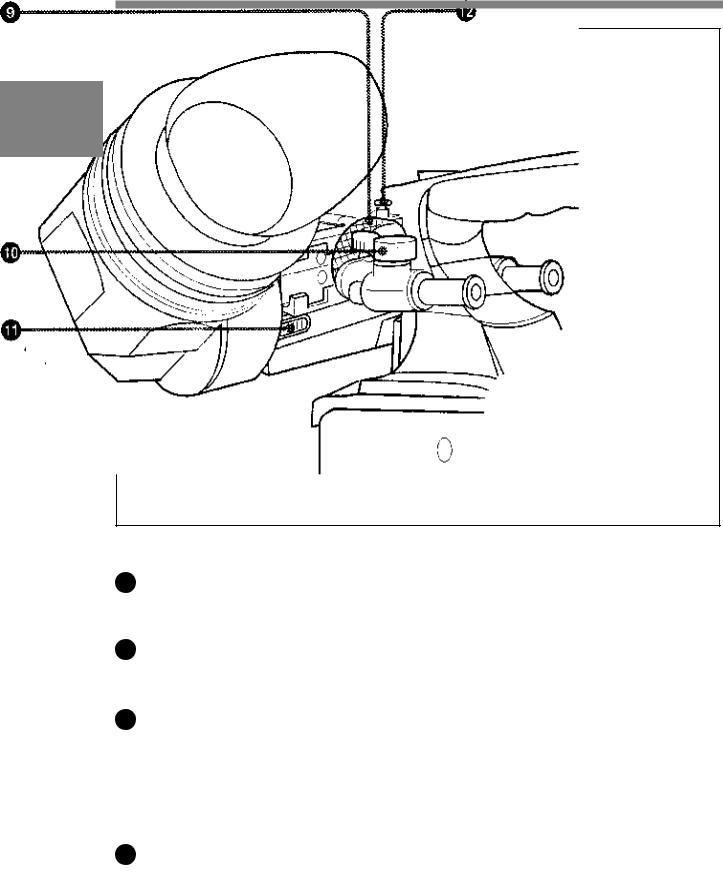
9 Viewfinder left-right positioning ring
Use this ring to move the viewfinder sideways.
10 Viewfinder front-rear positioning lever
Use this lever to move the viewfinder forward or backward.
11 Cameraman tally indicator
This indicator lights while the camcorder is operating.
Slide the window open when you shoot, keeping your eye away from the viewfinder. This indicator flashes when the battery level is running low or the tape is nearing its end.
12 Viewfinder stopper
Pull up this stopper to detach the viewfinder from the camera.
2-16 Chapter 2 Locations and Functions of Parts and Controls
 Loading...