


HD DIGITAL VIDEOCASSETTE PLAYER
HDW-M2100 HDW-M2100P
OPERATION MANUAL [English] 1st Edition (Revised 5)

WARNING
To prevent fire or shock hazard, do not expose the unit to rain or moisture.
To avoid electrical shock, do not open the cabinet. Refer servicing to qualified personnel only.
THIS APPARATUS MUST BE EARTHED.
AVERTISSEMENT
Afin d’éviter tout risque d’incendie ou d’électrocution, ne pas exposer cet appareil à la pluie ou à l’humidité.
Afin d’écarter tout risque d’électrocution, garder le coffret fermé. Ne confier l’entretien de l’appareil qu’à un personnel qualifié.
CET APPAREIL DOIT ÊTRE RELIÉ À LA TERRE.
WARNUNG
Um Feuergefahr und die Gefahr eines elektrischen Schlages zu vermeiden, darf das Gerät weder Regen noch Feuchtigkeit ausgesetzt werden.
Um einen elektrischen Schlag zu vermeiden, darf das Gehäuse nicht geöffnet werden. Überlassen Sie Wartungsarbeiten stets nur qualifiziertem Fachpersonal.
DIESES GERÄT MUSS GEERDET WERDEN.
This symbol is intended to alert the user to the presence of important operating and maintenance (servicing) instructions in the literature accompanying the appliance.
For the customers in the U.S.A.
This equipment has been tested and found to comply with the limits for a Class A digital device, pursuant to Part 15 of the FCC Rules. These limits are designed to provide reasonable protection against harmful interference when the equipment is operated in a commercial environment. This equipment generates, uses, and can radiate radio frequency energy and, if not installed and used in accordance with the instruction manual, may cause harmful interference to radio communications. Operation of this equipment in a residential area is likely to cause harmful interference in which case the user will be required to correct the interference at his own expense.
You are cautioned that any changes or modifications not expressly approved in this manual could void your authority to operate this equipment.
The shielded interface cable recommended in this manual must be used with this equipment in order to comply with the limits for a digital device pursuant to Subpart B of Part 15 of FCC Rules.
WARNING: THIS WARNING IS APPLICABLE FOR USA ONLY.
If used in USA, use the UL LISTED power cord specified below.
DO NOT USE ANY OTHER POWER CORD.
Plug Cap |
Parallel blade with ground pin |
|
(NEMA 5-15P Configuration) |
Cord |
Type SJT, three 16 or 18 AWG |
|
wires |
Length |
Less than 2.5 m (8 ft 3 in) |
Rating |
Minimum 10 A, 125 V |
Using this unit at a voltage other than 120V may require the use of a different line cord or attachment plug, or both.
To reduce the risk of fire or electrical shock, refer servicing to qualified service personnel.
WARNING: THIS WARNING IS APPLICABLE FOR OTHER COUNTRIES.
1.Use the approved Power Cord (3-core mains)/Appliance Connector/Plug with earthing-contacts that conforms to the safety regulations of each country if applicable.
2.Use the Power Cord (3-core mains lead)/Plug conforming to the following ratings, which meets power
supply voltage of each country. Rating: 10A or more
AVERTISSEMENT: CET AVERTISSEMENT EST VALABLE POUR LES AUTRES PAYS.
1.Utilisez le cordon (conducteur 3 âmes)/connecteur d’appareil et la fiche d’alimentation avec prise de terre, approuvés et conformes à la réglementation relative à la sécurité, adoptée par chaque pays.
2.Utilisez le cordon (conducteur 3 âmes) et la fiche d’alimentation correspondant aux caractéristiques
suivantes, en fonction de la tension d’alimentation secteur de chaque pays.
Ampérage: 10A ou plus
WARNUNG: Die folgenden Warnungsangaben gelten für das Modell für andere Länder.
1.Das Nezkabel (dreiadrig)/der Gerätestecker/der Netzstecker muss einen Erdungskontakt besitzen und den Sicherheitsbestimmungen lhres Landes genügen.
2.Das Netzkabel (dreiadrig) muss je nach der Netzspannung lhres Landes für folgende Spannungen und Ströme ausgelegt sein.
Stromstärke 10A oder mehr
For the customers in Europe
This product with the CE marking complies with both the EMC Directive (89/336/EEC) and the Low Voltage Directive (73/23/EEC) issued by the Commission of the European Community.
Compliance with these directives implies conformity to the following European standards:
•EN60950: Product Safety
•EN55103-1: Electromagnetic Interference (Emission)
•EN55103-2: Electromagnetic Susceptibility (Immunity) This product is intended for use in the following Electromagnetic Environment(s):
E1 (residential), E2 (commercial and light industrial), E3 (urban outdoors) and E4 (controlled EMC environment, ex. TV studio).
Pour les clients européens
Ce produit portant la marque CE est conforme à la fois à la Directive sur la compatibilité électromagnétique (EMC) (89/ 336/CEE) et à la Directive sur les basses tensions (73/23/ CEE) émises par la Commission de la Communauté européenne.
La conformité à ces directives implique la conformité aux normes européennes suivantes:
•EN60950: Sécurité des produits
•EN55103-1: Interférences électromagnétiques (émission)
•EN55103-2: Sensibilité électromagnétique (immunité) Ce produit est prévu pour être utilisé dans les environnements électromagnétiques suivants:
E1 (résidentiel), E2 (commercial et industrie légère), E3 (urbain extérieur) et E4 (environnement EMC contrôlé ex. studio de télévision).
Für Kunden in Europa
Dieses Produkt besitzt die CE-Kennzeichnung und erfüllt die EMV-Richtlinie (89/336/EWG) sowie die Niederspannungsrichtlinie (73/23/EWG) der EGKommission.
Angewandte Normen:
•EN60950: Sicherheitsbestimmungen
•EN55103-1: Elektromagnetische Verträglichkeit (Störaussendung)
•EN55103-2: Elektromagnetische Verträglichkeit
(Störfestigkeit),
für die folgenden elektromagnetischen Umgebungen:
E1 (Wohnbereich), E2 (kommerzieller und in beschränktem Maße industrieller Bereich), E3 (Stadtbereich im Freien) und E4 (kontrollierter EMV-Bereich, z.B. Fernsehstudio).

Table of Contents
Chapter 1
Overview
Chapter 2
Location and Function of
Parts
Chapter 3
Preparations
Chapter 4
Playback
Chapter 5
Shot Mark Function
Chapter 6
Tele-File
|
|
...........................................................................................1-1 Features |
1-1 |
||
|
|
1-2 Example System Configuration .................................................... |
1-3 |
||
|
|
2-1 Control Panels ................................................................................ |
2-1 |
||
|
2-1-1 |
Upper Control Panel .............................................................. |
2-2 |
||
|
|
2-1-2 Lower Control Panel .............................................................. |
2-3 |
||
|
2-1-3 |
Switch Panel ........................................................................ |
2-11 |
||
|
|
2-2 Connector Panel ........................................................................... |
2-13 |
||
|
|
3-1 Connections to External Devices ................................................... |
3-1 |
||
|
3-1-1 |
Connections to Digital Devices ............................................. |
3-1 |
||
|
3-1-2 |
Connecting Reference Signals ............................................... |
3-2 |
||
|
|
3-2 Setup |
................................................................................................ |
|
3-3 |
|
|
3-3 Superimposed Character Information ......................................... |
3-4 |
||
|
|
3-4 Cassettes .......................................................................................... |
3-6 |
||
|
3-4-1 |
Cassette Types ........................................................................ |
3-6 |
||
|
3-4-2 |
Inserting and Ejecting Cassettes ............................................ |
3-6 |
||
|
3-4-3 |
Preventing Accidental Recording of Shot Marks .................. |
3-7 |
||
|
|
3-5 Using a Memory Stick ..................................................................... |
3-8 |
||
|
|
3-5-1 Notes on Memory Stick .......................................................... |
3-8 |
||
|
4-1 Playback .......................................................................................... |
4-1 |
|||
|
4-1-1 |
Preparations for Playback ...................................................... |
4-1 |
||
|
4-1-2 |
Playback Procedures .............................................................. |
4-2 |
||
|
|
4-1-3 Dynamic Motion Control (DMC) Playback .......................... |
4-6 |
||
|
|
5-1 Overview ......................................................................................... |
5-1 |
||
|
|
5-2 Shot Mark Operation Menu .......................................................... |
5-2 |
||
|
|
5-3 Shot Mark Operations ................................................................... |
5-3 |
||
|
|
5-3-1 Reading Shot Marks .............................................................. |
5-3 |
||
|
|
5-3-2 Writing Post Marks ................................................................ |
5-3 |
||
|
5-3-3 |
Shot Mark List Operations .................................................... |
5-4 |
||
|
|
5-3-4 Cuing Up to Shot Marks ........................................................ |
5-6 |
||
|
|
5-3-5 Reading In Shot Data ............................................................. |
5-6 |
||
|
5-3-6 |
Sorting Shot Marks ................................................................ |
5-8 |
||
|
|
6-1 Overview of Tele-File Functions .................................................... |
6-1 |
||
|
|
6-2 Opening the Tele-File Menu .......................................................... |
6-2 |
||
|
|
6-3 Tele-File Menu ................................................................................ |
6-3 |
||
|
6-3-1 |
Clip Data Display .................................................................. |
6-3 |
||
|
|
6-3-2 Preroll and Cue Up Using Clip Data ..................................... |
6-6 |
||
|
|
6-3-3 Modifying Clip Data .............................................................. |
6-7 |
||
|
|
6-3-4 Undo/Resume Functions ...................................................... |
6-10 |
||
|
6-3-5 |
Displaying and Modifying Attribute Data ........................... |
6-11 |
||
|
|
|
|
|
|
|
|
|
|
|
|
|
|
|
|
|
|
|
Table of Contents |
1 |
|
|
|

Table of Contents
Chapter 7
UMID Functions
Chapter 8
Function Menu
Chapter 9
Setup Menus
Chapter 10
Maintenance and
Inspection
Appendix
|
|
|
.......................................................7-1 Overview of UMID Functions |
7-1 |
|
|
|
7-2 UMID Output and Display ............................................................ |
7-2 |
|
|
|
7-2-1 UMID Output Settings ........................................................... |
7-2 |
|
|
|
7-2-2 UMID Display ....................................................................... |
7-2 |
|
|
|
8-1 Overview ......................................................................................... |
8-1 |
|
|
|
8-1-1 Function Menu Configuration ............................................... |
8-1 |
|
|
|
8-1-2 Using the Function Menu ...................................................... |
8-2 |
|
|
|
8-2 Function Menu Item List ............................................................... |
8-3 |
|
|
|
9-1 Setup Menu Configuration ............................................................ |
9-1 |
|
|
|
9-2 Setup Menu Operations ................................................................. |
9-2 |
|
|
|
9-3 Items in the Basic Setup Menu ...................................................... |
9-7 |
|
|
|
9-4 Items in the Extended Setup Menu ............................................. |
9-10 |
|
|
|
10-1 Removing a Cassette When Tape Slack .................................... |
10-1 |
|
|
|
10-2 Head Cleaning ............................................................................ |
10-1 |
|
|
|
10-3 Error Messages ........................................................................... |
10-2 |
|
|
|
10-4 Moisture Condensation .............................................................. |
10-4 |
|
|
|
10-5 Regular Checks ........................................................................... |
10-5 |
|
|
|
10-5-1 Digital Hours Meter ........................................................... |
10-5 |
|
|
|
10-5-2 Maintenance Timings ........................................................ |
10-6 |
|
|
|
Specifications ......................................................................................... |
A-1 |
|
|
|
Index |
I-1 |
|
|
|
||
|
|
|
|
|
2 Table of Contents
1-1 Features
The HDW-M2100/M2100P is a high-definition (HD) digital videocassette player based on the HDCAM format.
This unit uses large scale integrated circuits for signal processing, and has a simple internal construction, allowing it to provide functionality at least equivalent to a conventional VTR in a compact (4U size), lightweight, and low power consumption design.
In addition to HDCAM format playback, the unit can also play back tapes recorded in the Digital Betacam, MPEG IMX, Betacam SX, and analog Betacam formats.
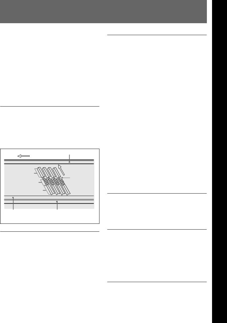
HDCAM format
The HDCAM format uses the same 12.65-mm width tape as the conventional Betacam series. It provides high definition images, offering up to two hours of recording. For video signal compression, prefiltration and coefficient recording technologies are used.
CUE track
Direction of tape travel
Video
Direction of head motion
Audio |
SATa) |
|
|
Video |
|
Control (CTL) track |
Time code track |
a) Supplemental Automatic Tracking signal
High-performance heads and compatibility playback functions
The newly developed high-performance heads and dynamic tracking (DT) technology provide highdensity playback in narrow tracks with high reliability. In addition to HDCAM playback heads, the unit is equipped with Betacam SX playback heads and analog Betacam DT heads, for playback compatibility with existing recording formats. The VTR automatically detects the recording format of tapes when they are loaded, so that no menu settings need to be made when changing formats.
High-precision digital signal processing and range of interfaces
The digital signal processing uses HD 4:2:2 component video signals complying with SMPTE 292M, which are converted into parallel data and then compressed into HDCAM format.
The audio signals are based on AES/EBU format, and are subjected to digital signal processing without being compressed.
The unit is equipped with a high definition to standard definition (HD to SD) downward converter, and has the following interfaces as standard equipment, for ease of connection to different external devices.
•SD analog composite signal output
•SD analog component signal output
•Analog audio signal input/output (4 channels)
•HDSDI SMPTE 292M input/output (HD digital video/audio, 4 channels)
•SDI SMPTE 259M output (component digital video/ audio, 4 channels)
•AES/EBU serial digital audio input/output (4 channels)
•SDTI SMPTE 305M input/output (HDCAM video/ audio data) (option)
•Time code input/output
•CUE audio output
High quality four-channel audio
High quality 20 bit/48 kHz AES/EBU digital audio is supported. There are four digital audio input/output channels, and four analog audio input/output channels.
Playback of SDTI compressed data (optional)
This unit can be fitted with SDTI input/output complying with SMPTE 305M, and can therefore be used for transferring HDCAM data, audio data, metadata, and so on to a VTR or nonlinear device via an SDTI interface.
Multifunction control panel
While built in a compact 4U size, this unit has a front panel which provides a wide range of functions while maintaining existing operability.
1 Chapter
OverviewChapter1
rviewOv
Chapter 1 Overview 1-1

Overview 1 Chapter
1-1 Features
Basic operation buttons and jog/shuttle dial
The basic buttons and jog/shuttle dial for VTR and editing operations are provided in the conventional VTR layout, ensuring continuity with conventional operating panels.
Time data display
This can be selected to display a CTL counter value, time code value, or time code user bits. It can also display edit points and edit durations.
Menu-based control interface
The time data/menu display shows not only various values and settings, but also the pages of a menu system for commonly used functions. You can use the function keys and MULTI CONTROL knob to easily change settings.
Other operation settings, including interfacing with external devices, can be set from the control panel by the same type of setup menu system as on a conventional VTR.
High quality variable speed playback and digital jog sound function
In HDCAM format playback, the dedicated playback DT heads allow smooth, noiseless playback. During Betacam SX playback, noiseless playback is achieved through unique multihead playback technology.
In slow motion operation, the digital jog sound function provides the same ease of operation as for a conventional analog VTR.
DMC editing
This allows automatic playback with a varying speed memorized beforehand for the desired segment.
Downward converter function
The unit has an HD-to-SD downward converter function, and can output standard definition SDI, analog component and analog composite signals even while playing back an HDCAM format tape.
Upward converter function
The unit features a standard definition to high definition (SD-to-HD) upward converter as standard equipment. This allows high-quality HD signals to be output even when playing back tapes recorded in formats other than HDCAM.
Tele-File functions
Tele-File enables data writing/reading between cassettes with memory labels and VTRs. It increases the efficiency of operations such as cuing up and playback, and source data management.
Remote control function
This unit can be controlled from an external remote controller or editor through an interface complying with RS-422A (serial 9-pin). Since two remote control connectors are provided, you can also control a number of VTRs simultaneously.
Additionally, a parallel (50-pin) interface is also fitted as standard, supporting easy external control through the parallel interface.
Rack mounting
Using the optional RMM-131 Rack Mount Adaptor, you can mount the unit in a standard EIA 19-inch rack.
For details of rack mounting, refer to the Installation Manual.
1-2 Chapter 1 Overview
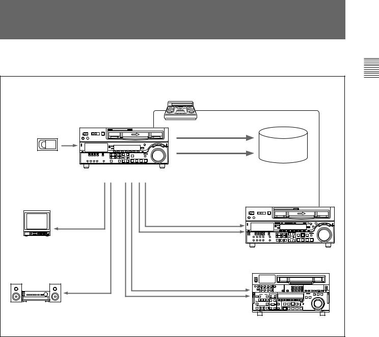
1-2 Example System Configuration
The following conceptual diagram shows an example of use.
|
|
Tape control |
1Chapter |
|
|
BVE-series editor |
|
|
|
SDTI (optional) |
Overview |
|
|
|
|
|
|
HDSDI |
Audio/video |
|
|
server system |
|
Digital cassette |
|
|
|
|
|
|
|
|
HDW-M2100/M2100P |
|
|
HDSDI/Analog |
|
SDTI (optional) |
|
composite |
|
|
|
|
|
|
|
Video monitor |
|
HDSDI |
|
|
|
|
|
|
|
|
HD VTR |
|
|
Analog composite/component |
|
Analog audio |
SDI |
|
|
Audio monitor |
|
|
|
|
|
|
|
|
|
|
SD VTR or analog VTR |
Chapter 1 Overview 1-3
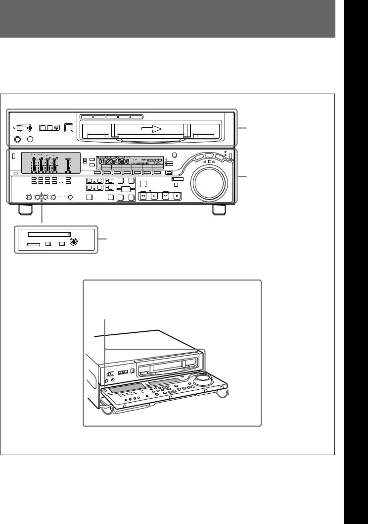
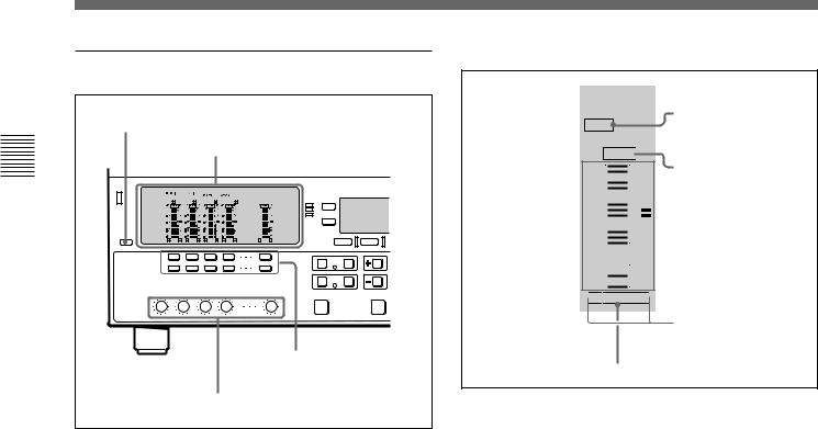
2-1 Control Panels
There are three control panels, as follows:
•Upper control panel
•Lower control panel
•Switch panel
Z |
Upper control panel (see page 2-2) |
59.94
CTL/TC MENU
TC
Lower control panel (see page 2-3)
|
|
CONTROL PANEL |
Switch panel (access by opening the lower control panel) (see page 2-11) |
KEY INHI |
PANEL SEL |
|
|
ON OFF |
REAR FRONT |
|
|
Lower control panel unlock buttons.
Push in to open the lower control panel.
2 Chapter
LocationChapter
2
FunctionandLocationand
of Fuction
Parts
P of arts
Chapter 2 Location and Function of Parts |
2-1 |
Parts of Function and Location 2 Chapter
2-1 Control Panels |
|
|
|
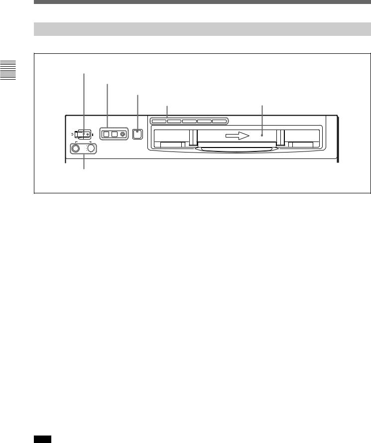
2-1-1 Upper Control Panel |
|
||
1 POWER switch |
|
|
|
2 REMOTE buttons and RS-232C indicator |
|
||
|
|
3 EJECT button |
|
|
|
4 Format indicators |
Cassette compartment |
|
|
|
|
|
|
BETACAM/SP BETACAM SX MPEG IMX Digital BETACAM |
HDCAM |
POWER |
REMOTE |
EJECT |
|
1(9P) |
2(50P) RS-232C |
|
|
|
|
Z |
|
PHONES |
|
|
|
5 PHONES jack and control |
|
||
1 POWER switch |
4 Format indicators |
Pressing the ‘ ) ’ side of the switch powers the unit on. When the unit is powered on, the audio setting display section (see page 2-4) and the time data/menu display section (see page 2-6) light.
2 REMOTE buttons and RS-232C indicator
Press the 1 (9P) button or 2 (50P) button to select the device controlling this unit.
1(9P): This unit is controlled by the device connected to the REMOTE 1-IN(9P) or REMOTE 1-OUT(9P) connector. The button lights when pressed.
2(50P): This unit is controlled by the device connected to the REMOTE 2 PARALLEL I/O(50P) connector. The button lights when pressed.
RS-232C indicator: This indicator lights when this unit is controlled through the RS-232C connector.
3 EJECT button
To eject the cassette, press this button. While the cassette is being ejected, this button lights.
When using the lower control panel as remote control panel, press the DELETE button and STOP button at the same time to eject the cassette.
Note
Ejecting with the EJECT button is a local operation. It is not possible to eject a cassette in another unit by remote control.
The indicator (BETACAM/SP, BETACAM SX, MPEG IMX, Digital BETACAM, or HDCAM) corresponding to the current recording or playback format lights. The BETACAM/SP lights when the format is Betacam or Betacam SP.
5 PHONES jack and control
Connect stereo headphones with an impedance of 8 ohms, to monitor the sound during playback and editing.
The control knob adjusts the volume.
It is possible to set an internal board switch so that the output volume from the MONITOR OUTPUT L and R connectors is controlled simultaneously.
For details, refer to the Installation Manual.
2-2 |
Chapter 2 Location and Function of Parts |

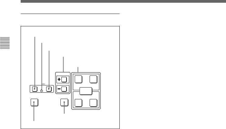
2-1-2 Lower Control Panel
4
 Time data/menu display section (see page 2-6)
2CHANNEL CONDITION
indicator (see page 2-5) 5
MULTI CONTROL knob and PUSH/ SHIFT indicator (see page 2-7)
3Menu control buttons
1Audio control section (see page 2-5) 6RESET button (see page 2-7) (see page 2-4)
59.94
CTL/TC MENU
TC
7Search control section (see page 2-7)
8Tape transport control section (see page 2-9)
9ALARM indicator and KEY INHI indicator (see page 2-9)
59.94
CTL/TC MENU
TC
q;Editing control section (see page 2-10)
qaShot mark section (see page 2-11)
Parts of Function and Location 2 Chapter
Chapter 2 Location and Function of Parts |
2-3 |
2-1 Control Panels
Parts of Function and Location 2 Chapter
1 Audio control section
1 DISPLAY FULL/FINE button |
2 Audio setting display section |
3 Audio monitor |
signal selection |
buttons |
4 PB controls |
1 DISPLAY FULL/FINE button
Pressing this button toggles the display mode of the level meters in the audio setting display section between FULL and FINE.
FULL: The display covers the range –60 dB to 0 dB or –40 dB to +20 dB as selected using setup menu item 806. In this mode the segment of the display corresponding to the current audio level and all lower segments light.
FINE: The display is enlarged, with a step of
0.25 dB. A segment indicating the reference level lights. In this mode only the segment of the display corresponding to the current audio level lights. If the audio level exceeds the maximum display level, the top segment flashes, and if the audio level goes below the minimum display level, the bottom segment flashes.
2 Audio setting display section
DATA indicator
DATA
dB OVER dB
dB
0 |
20 OVER indicator |

 2 -10
2 -10

 110
110
-20

 0
0 
 Level meter
-1
-30

 -10
-10
-40

 -20
-20 

 -2
-2
-60

 -40
-40
 L
L 
 EMPH
EMPH
 R
R
Monitor channel L and R indicators
EMPH indicator
DATA indicator: Lights when the audio signals are recognized as data signals.
OVER indicator: While the unit is in playback mode, this lights when the level of the audio signal on the corresponding channel exceeds the maximum level that can be indicated on the level meter.
Level meter: Displays the audio signal level when the unit is in playback mode. You can use the setup menu to switch the display mode between PEAK.0 (0 dB is maximum level) and REF.0 (0 dB is the reference level). You can also use the DISPLAY FULL/FINE button 1 to enlarge the display only near the reference level.
Monitor channel L and R indicators: Indicate whether or not the signals of the track are output to the MONITOR OUTPUT L/R connectors and PHONES jack. ‘L’ lights to indicate output to the left monitor channel, and ‘R’ lights to indicate output to the right monitor channel.
EMPH (emphasis) indicator: While the unit is in playback mode, this lights when the emphasis setting is on for the audio signal on the corresponding track.
2-4 |
Chapter 2 Location and Function of Parts |

3 Audio monitor signal selection buttons (CH1 to CH4, and CUE)
The buttons in the upper and lower rows select tracks to be output to the MONITOR OUTPUT L and R connectors on the connector panel or the PHONES jack on the upper control panel. The buttons in the upper row (L row) select tracks for output to the MONITOR OUTPUT L connector, and the buttons on the lower row (R row) select tracks for output to the MONITOR OUTPUT R connector. You can obtain the mixed output of multiple tracks by simultaneously pressing multiple buttons in the upper or lower rows. For example, simultaneously press the CH1, CH2, and CH3 buttons in the upper row to mix the signals of audio tracks 1, 2, and 3 for output to the MONITOR OUTPUT L connector.
To monitor CH5 to CH8 in MPEG IMX playback, press the CUE button to switch between CH1 to CH4 and CH5 to CH8, and then select the desired channels.
4 PB (playback) controls
These adjust individually the playback levels on channels 1 to 4, and cue audio.
During playback, press to protrude the control knobs and adjust the level while monitoring the audio level indication on the level meters in the audio setting display section.
When the control knobs are pushed in, the playback levels return to the preset levels, and cannot be adjusted.
2 CHANNEL CONDITION indicator
A three-color indicator shows the state of the playback signal.
Green: The state of the playback signal is good. Yellow: The playback signal is somewhat
deteriorated, but playback is possible. Red: The playback signal is deteriorated.
When this indicator remains on, head cleaning or an internal inspection is necessary.
3 Menu control buttons
These buttons are used for function menu (see the following section “Overview of the function menu”) and setup menu (see Chapter 9) operations. The page buttons (V, v, and HOME) select menu pages, and the function buttons (F1 to F6) make function settings.
V: Selects the next page in the order HOME t 1 t 2 t 3 t 4 t HOME.
v: Selects the next page in the order HOME t 4 t 3 t 2 t 1 t HOME.
HOME: Selects the function menu HOME page.
F1 to F6: Make settings for the items displayed in the upper line of the menu display (the menu item display line). Pressing one of these buttons changes the setting for the corresponding item and displays the setting in the lower line of the menu display.
If there is no setting displayed in the lower line of the menu display, even though a menu item is displayed in the upper line, pressing the corresponding function button moves to a lower menu level.
Overview of the function menu
The function menu provides convenient access to frequently used function settings, such as input video signal selection and time code settings.
For details on the function menu, see Chapter 8.
Parts of Function and Location 2 Chapter
Chapter 2 Location and Function of Parts |
2-5 |
Parts of Function and Location 2 Chapter
2-1 Control Panels
4 Time data/menu display section
|
1 Time data display |
|
59.94 |
1 |
CTL/TC MENU |
|
TC |
|
2 Menu display |
1 Time data display
This displays indicators relating to time data and other indicators.
Time data display area 1
Time data type indicator
DF indicator
LTC indicator
VITC indicator
Capstan lock mode indicator
System frequency indicator
Tape format/line standard indicator
DOLBY NR indicator
59.94 |
Speed indication area
Time data display area 2
Time data display area 1
Normally this displays a CTL count, time code value, or user bit value according to the setting in function menu HOME page for F4 (CTL/TC).
Time data type indicator
This indicates the type of data displayed in the time data display area 1.
LTC (longitudinal time code): Time code recorded on a longitudinal track on the tape
LUB: LTC user bit values
VITC (vertical interval time code): Time code recorded in the vertical blanking interval
VIUB: VITC user bit value
DF (drop-frame) indicator (for 59.94i, 29.97PsF mode only)
This lights when values of drop-frame mode time code are displayed.
LTC indicator
Regardless of the display in the time data display
area 1, this indicator lights when LTC values are being read.
VITC indicator
Regardless of the display in time data display area 1, this indicator lights when VITC values are being read.
Capstan lock mode indicator
This indicates the capstan lock mode (2F or 4F) set in function menu page 4 or in setup menu item 106.
System frequency indicator
This indicator shows the current system frequency.
Tape format/line standard indicator
This shows information about the tape format and the line standard conversion status.
Following are some examples and their meanings. IMX 1080: Signals recorded in MPEG IMX format
are output after conversion to 1080 line standard format signals.
DB 1035: Signals recorded in Digital Betacam format are output after conversion to 1035 line standard format signals.
1035t1080: HDCAM signals recorded in 1035 line standard format are output after conversion to 1080 line standard signals.
HD 1080: HDCAM signals recorded in 1080 line standard format are output with no change.
2-6 |
Chapter 2 Location and Function of Parts |
DOLBY NR indicator
This lights when the Dolby noise-reduction 1) circuit is functioning.
Speed indication area
This indicates the speed of a DMC playback.
During a DMC playback, “DMC SPD” is displayed in time data display area 2. However, CONFI playback is not possible during editing.
Time data display area 2
Displays data types and time data such as the time code of edit points and the total time of that tape. The following data types are shown.
TOTL: Total time of the tape. REM: Remaining time on the tape.
Depending on the setting of F5 (T INFO) on function menu page 3, either TOTL (TOTAL) or REM (REMAIN) is displayed.
The values displayed are approximate values calculated on the basis of the detected tape diameter. They are not precise to units of seconds.
The following appear when the top or end of the tape is reached.
BOT: Returned to top of tape. EOT: Reached end of tape.
IN: video IN point OUT: video OUT point AIN: audio IN point AOUT: audio OUT point DUR: duration value
TCG (time code generator): time code generated by the internal time code generator
2 Menu display
This displays the function menu and setup menu.
For details on the function menu, see Chapter 8 and for details on the setup menu, see Chapter 9.
5 MULTI CONTROL knob and PUSH/ SHIFT indicator
In function menu operations, rotate the MULTI CONTROL knob to change settings that flash in the menu display section. In setup menu operations, rotate this knob to select menu items.
The PUSH/SHIFT indicator lights when you press this knob in. In this state, the value of the setting changes by a greater amount when you rotate the knob.
6 RESET button
To reset a CTL, time code (TC) or user bit (UB) value displayed in time data display area 1, hold this button down.
Resetting the CTL value erases all edit points.
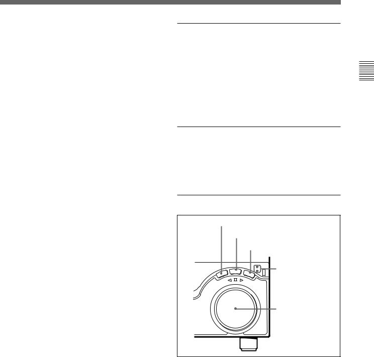
7Search control section
1 SHUTTLE button
2 JOG button
3 VAR button
|
|
SHUTTLE/VAR |
4 SHUTTLE/VAR |
|
JOG |
JOG |
|
|
VAR |
and JOG |
|
SHUTTLE |
|
||
|
|
||
S |
|
FORWARD |
indicators |
R |
|
|
|
E |
|
|
|
R |
|
|
|
E |
|
|
|
V |
|
|
|
E |
|
|
|
|
|
|
5 Search dial |
1 SHUTTLE button
To use the search dial for playback in shuttle mode, press this button, turning it on.
For details of playback in shuttle mode, see the description of the search dial 5.
..........................................................................................................................................................................................................
1)Dolby noise reduction: Dolby noise reduction manufactured under license from Dolby Laboratories Licensing Corporation. “DOLBY” and the double-D symbol ; are trademarks of Dolby Laboratories Licensing Corporation.
Parts of Function and Location 2 Chapter
Chapter 2 Location and Function of Parts |
2-7 |

Parts of Function and Location 2 Chapter
2-1 Control Panels
2 JOG button
To use the search dial for playback in jog mode, press this button, turning it on.
For details of playback in jog mode, see the description of the search dial 5.
3 VAR (variable) button
To use the search dial for playback in variable speed mode, press this button, turning it on.
For details of playback in variable speed mode, see the description of the search dial 5.
4 SHUTTLE/VAR and JOG indicators
Either of the indicators is lit to show the current search mode or the mode used last.
When the SHUTTLE/VAR indicator is lit: Shuttle or variable speed mode
When the JOG indicator is lit: Jog mode When the unit is turned on, the SHUTTLE/VAR indicator lights.
5 Search dial
Turn this to carry out playback in the modes shown in the following table. Turning the dial clockwise lights the H indicator and plays back in the forward direction. Turning the dial counterclockwise lights the h indicator and plays back in the reverse direction. When the tape is stopped or the unit is turned on, the s indicator lights. Pressing the dial toggles between shuttle and jog modes or between variable speed and jog modes.
Depending on the tape format, noiseless playback is possible in the following ranges.
HDCAM: –1 to +2 times normal speed Digital Betacam: –1 to +3 times normal speed MPEG IMX: –1 to +3 times normal speed Betacam SX: –1 to +2 times normal speed
Betacam/Betacam SP: –1 to +3 times normal speed
Playback modes using the search dial
Playback mode |
Operations and functions |
|
|
Shuttle |
Press the SHUTTLE button or the |
|
search dial so that the SHUTTLE |
|
button lights, then turn the search dial. |
|
Playback is carried out at a speed |
|
determined by the position of the |
|
search dial. Playback speed ranges |
|
are as follows. |
|
• HDCAM tape: ±50 times normal |
|
speed (59.94i, 29.97PsF mode), ±58 |
|
times normal speed (50i, 25PsF |
|
mode), ±60 times normal speed |
|
(24PsF, 23.98PsF mode) |
|
• Digital Betacam tape: ±50 times |
|
normal speed |
|
• MPEG IMX tape: ±60 times normal |
|
speed |
|
• Betacam SX tape: ±60 times normal |
|
speed |
|
• Analog Betacam tape: ±35 times |
|
normal speed (525/59.94 mode), |
|
±42 times normal speed (625/50 |
|
mode) |
|
The search dial has detents at the still |
|
position and at ±5 times normal |
|
speed. |
|
The maximum shuttle mode playback |
|
speed can be changed by changing |
|
the setting of setup menu item 102 |
|
(see page 9-10). |
|
|
Jog |
Press the JOG button or the search |
|
dial so that the JOG button lights, then |
|
turn the search dial. Playback is |
|
carried out at a speed determined by |
|
the speed of rotation of the search |
|
dial. The playback speed range is ±1 |
|
time normal speed. |
|
The search dial has no detents. |
|
|
Variable speed |
Press the VAR button, turning it on, |
|
then turn the search dial. You can |
|
control the playback speed finely (a |
|
maximum of 51 steps) in the range in |
|
which noiseless playback is possible. |
|
• HDCAM, Betacam SX: Maximum 51 |
|
steps |
|
• Digital Betacam , MPEG IMX, analog |
|
Betacam: Maximum 54 steps |
|
The search dial has detents at the still |
|
position and at the normal speed |
|
position. |
|
|
Capstan override |
For details on operation, see page |
|
4-4. |
|
|
Setting setup menu item 101 (see page 9-10) to KEY enables you to use only the SHUTTLE, JOG, and VAR buttons to select shuttle/jog/variable speed modes.
2-8 |
Chapter 2 Location and Function of Parts |
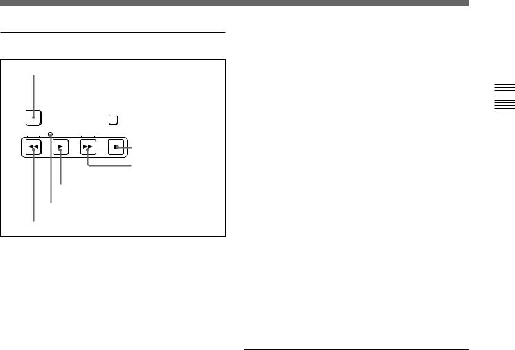
8 Tape transport control section
1 PREROLL button
PREROLL
STANDBY
 2 STANDBY button
REW |
PLAY |
F FWD |
STOP |
|
|
3 STOP button
4 F FWD button
5 PLAY button
6 SERVO indicator
7 REW button
1 PREROLL button
Press this button to cue up to the preroll point (before the IN point by the time set as the preroll time) on the tape. You can change or select the preroll time and the state of the unit at the end of preroll (“stop mode” 1) or still playback mode) using setup menu item 001 or 401.
Cuing up to DMC playback control points
Hold down the STUNT IN, STUNT OUT, PLAY IN, or PLAY OUT button while pressing this button to cue up to the corresponding DMC playback control point.
2 STANDBY button
When this button is off with a cassette inserted in the unit, to put the unit in standby mode, press the button, turning it on.
In standby mode, the drum is rotating and the tape is in contact with the drum. As a result, playback can start immediately.
To end standby mode, press the STANDBY button, turning it off.
If 8 minutes (value can be varied using setup menu item 501) elapse in standby mode, the unit automatically switches out of standby mode to protect the tape.
3 STOP button
To stop playback, press this button, turning it on.
Fault display function
The STOP button flashes in the following cases:
•When setup menu item 105 is set to ON, there is no external reference signal input.
•The input external reference signal is different from the signal specified by setup menu item 337.
4 F FWD (fast forward) button
To fast forward the tape, press this button, turning it on.
5 PLAY button
To start playback, press this button, turning it on.
To operate in capstan override mode
Hold down this button, and turn the search dial.
For details of capstan override mode, see page 4-4.
6 SERVO indicator
Lights when the drum servo and capstan servo are locked.
7 REW (rewind) button
To rewind the tape, press this button, turning it on.
9 ALARM indicator and KEY INHI indicator
ALARM indicator
This lights when a hardware error is detected on the unit, and goes off when the error is resolved.
When this indicator is lit, an error message appears in the time data/menu display section. If you are using the HDSDI OUTPUT 3 (SUPER), SDI OUTPUT 3 (SUPER) or COMPOSITE VIDEO OUTPUT 3 (SUPER) connector, then when the setting of F4 (CHARA) in function menu page 4 is ON, the error message also appears on the monitor screen.
For details on error messages, refer to Section 1-24 in the Maintenance Manual Volume 1.
KEY INHI (inhibit) indicator
This indicator lights when the KEY INHI switch on the switch panel (see page 2-11) is set to ON.
..........................................................................................................................................................................................................
1)Stop mode: The state in which the device currently the subject of operation is stopped, and the STOP button is lit.
Parts of Function and Location 2 Chapter
Chapter 2 Location and Function of Parts |
2-9 |
Parts of Function and Location 2 Chapter
2-1 Control Panels
q; Editing control section
1 DMC EDIT button
2 MEMORY indicator
3 DELETE button
4 TRIM buttons
|
5 DMC playback control |
|
|
|
point setting buttons |
|
TRIM |
|
|
IN |
PLAY OUT |
DMC EDIT |
DELETE |
ENTRY |
|
|
|
MEMORY |
|
|
LEARN |
CUE/PLAY |
|
|
IN |
STUNT OUT |
6 CUE/PLAY button
7 LEARN button
1 DMC EDIT button
Use this button to memorize the playback speed varied between –1 and +2 times normal speed, and carry out automatic playback or automatic editing using the memorized playback speed.
2 MEMORY indicator
When memorizing the playback speed using the DMC EDIT button, this indicator flashes as the playback speed is captured to memory, and lights continuously once the speed is captured.
3 DELETE button
This deletes an existing edit point.
Hold down this button and press the STUNT IN, STUNT OUT, PLAY IN, or PLAY OUT button which is lit, indicating an existing edit point, to delete the corresponding edit point. The button either goes off or flashes. When the button flashes, it is necessary to set the deleted edit point again.
To cancel the DMC mode, hold down the DMC EDIT button and press the DELETE button.
4 TRIM buttons
Use these buttons to trim an edit point to single-frame precision.
Hold down the STUNT IN, STUNT OUT, PLAY IN, or PLAY OUT button, and press one of these buttons. The ‘+’ button advances the corresponding edit point by one frame, and the ‘–’ button sets it back by one frame.
Pressing one of these buttons while holding down the PLAY button adjusts the tape speed by +8% or –8% correspondingly. (Capstan override function)
5 DMC playback control point setting buttons PLAY IN button and PLAY OUT button
To set an on-air start or end point, hold down the PLAY IN button or PLAY OUT button, and press the ENTRY button.
After you have made the setting, pressing the PLAY IN button or PLAY OUT button displays the on-air start or end point set in time data display area 2.
STUNT IN button and STUNT OUT button
To set a speed variation start or end point, hold down the STUNT IN button or STUNT OUT button, and press the ENTRY button.
After you have made the setting, pressing the STUNT IN button or STUNT OUT button displays the speed variation start or end point set in time data display area 2.
ENTRY button
Use this for setting DMC playback control points and so on.
•To set a speed variation start or end point: Hold down the STUNT IN button or STUNT OUT button, and press this button.
•To set an on-air start or end point: Hold down the PLAY IN button or PLAY OUT button, and press this button.
6 CUE/PLAY (cue up/playback) button
After setting an on-air start point (PLAY IN point) or an on-air end point (PLAY OUT point), pressing this button cues up the tape to the on-air start point. The button then starts flashing to indicate that the unit is ready for DMC playback operation. To start DMC playback, press the button again.
2-10 |
Chapter 2 Location and Function of Parts |

7 LEARN button
After setting a speed variation start point (STUNT IN point) and a speed variation end point (STUNT OUT point), pressing this button makes the tape start running. You can then use the search dial to vary the tape speed, which is automatically stored in memory. After thus storing the tape speed variation in memory, pressing this button starts an automatic playback between the speed variation start and end points at the stored speed.
qa Shot mark section
1 LIST button
LIST GOOD SHOT MARK |
2 REC/ERASE indicator |
|
|
REC/ |
3 MARK button |
ERASE |
1 LIST button
Use this button to read in and list shot marks.
2 REC/ERASE indicator
This lights in the state in which writing, amending, and deleting of shot marks is enabled and flashes while a shot mark is actually being written, amended or deleted.
3 MARK button
Hold this button down for 2 seconds or more, to enable writing, amending, and deleting of shot marks.
Parts of Function and Location 2 Chapter
2-1-3 Switch Panel
To access the switch panel, open the lower control panel.
On how to open the lower control panel, see the figure on page 2-1.
1 Memory card slot
2 Memory card ejection button
3 CONTROL PANEL connector
CONTROL PANEL
KEY INHI |
PANEL SEL |
ON OFF REAR FRONT
4 PANEL SELECT switch
5 KEY INHI switch
6 Memory stick slot
Chapter 2 Location and Function of Parts |
2-11 |

Parts of Function and Location 2 Chapter
2-1 Control Panels
1 Memory card slot
Insert a memory card to update this unit’s firmware. You can save or load setup menu settings onto the memory card.
For details on firmware update and setup menu reading/ storing, refer to the Maintenance Manual Volume 1.
2 Memory card ejection button
Press to eject a memory card from the memory card slot.
3 CONTROL PANEL connector (10-pin, round type)
Plug in the lower control panel connection cable.
4 PANEL SELECT switch
In addition to the lower control panel, you can connect a similar control panel to this unit. When two control panels are connected to the unit, the PANEL SELECT switch is used to specify which panel be enabled to control the unit.
FRONT: Enables the control panel connected to the CONTROL PANEL connector on the switch panel.
REAR: Enables the control panel connected to the CONTROL PANEL connector on the connector panel. When setup menu item 117 is set to PARA, this switch position also enables the control panel connected to the CONTROL PANEL connector on the switch panel.
5 KEY INHI switch
Moving this switch to the ON position disables the controls on the upper and lower control panels.
You can specify which buttons and knobs are disabled in setup menu item 118.
6 Memory stick slot
Use this to update the firmware. You can also save or load setup menu settings onto the memory stick.
Note
After inserting a memory stick or memory card, allow at least five seconds to elapse before removing it.
For details on firmware update and save or load setup menu settings, refer to the Maintenance Manual Volume 1.
2-12 |
Chapter 2 Location and Function of Parts |
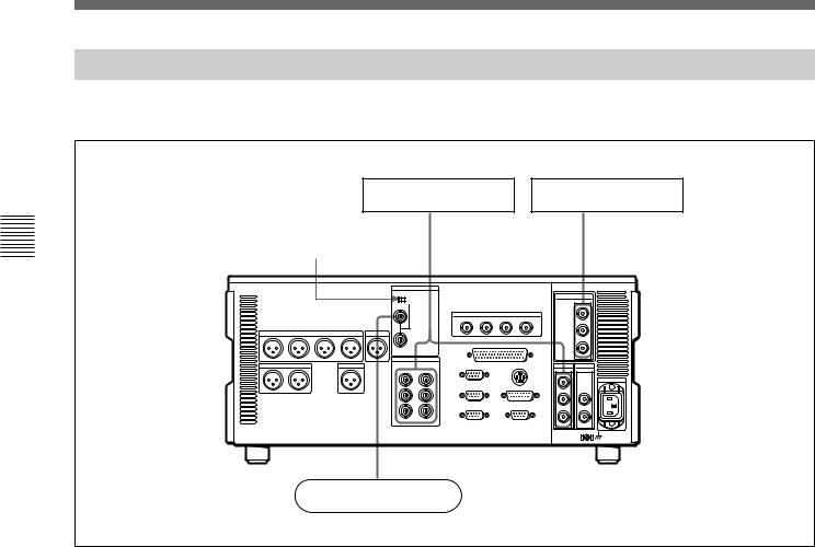
2-2 Connector Panel
Cooling fan |
|
2Analog video input/output section |
1Analog audio output |
|
3Digital audio output section (see page 2-14) |
section |
|
|
|
75Ω |
4Digital signal output |
|
|
|
|
|
section (see page |
|
|
2-14) |
|
|
Cooling fan |
|
|
5Power supply section |
|
|
(see page 2-15) |
7Time code output section |
6External device connectors (see page 2-15) |
(see page 2-16) |
|
8Audio monitor signal output section (see |
|
page 2-16) |
|
1 Analog audio output section |
|
2 Analog video input/output section |
1 AUDIO OUTPUT CH1 to CH4 connectors
|
|
AUDIO OUTPUT |
|
CUE |
CH1 |
CH2 |
CH3 |
CH4 |
OUT |
2 CUE OUT connector
1 AUDIO OUTPUT CH1 to CH4 (channels 1 to 4) connectors (XLR 3-pin, male)
These connectors output analog audio signals for channels 1 to 4.
2 CUE OUT (cue audio output) connector (XLR
3-pin, male)
This connector outputs the analog cue audio signals.
REF INPUT INPUT 1125/525
OFF

 ON
ON
75Ω
VIDEO OUTPUT
COMPOSITE COMPONENT
1Y
2R-Y
3
(SUPER) B-Y
1REF.VIDEO INPUT connectors and 75Ω termination switch
2COMPONENT VIDEO OUTPUT connectors
3COMPOSITE VIDEO OUTPUT connectors
Parts of Function and Location 2 Chapter
Chapter 2 Location and Function of Parts |
2-13 |
Parts of Function and Location 2 Chapter
2-2 Connector Panel
1 REF. (reference) VIDEO INPUT connectors (BNC type) and 75Ω termination switch
Input a reference video signal. Input a three-valued (positive and negative) sync signal, a video signal with chroma burst (VBS) or a monochrome video signal (VS). When using the loop-through connection set the switch to the OFF position, and otherwise to the ON position.
2 COMPONENT VIDEO OUTPUT connectors (BNC type)
These connectors output analog component video signals (Y/R–Y/B–Y).
3COMPOSITE VIDEO OUTPUT connectors (BNC type)
These connectors output analog composite video signals.
When the setting of F4 (CHARA) in function menu page 4 is ON, connector 3 (SUPER) outputs a signal with superimposed time code, menu settings, alarm messages, and other text information.
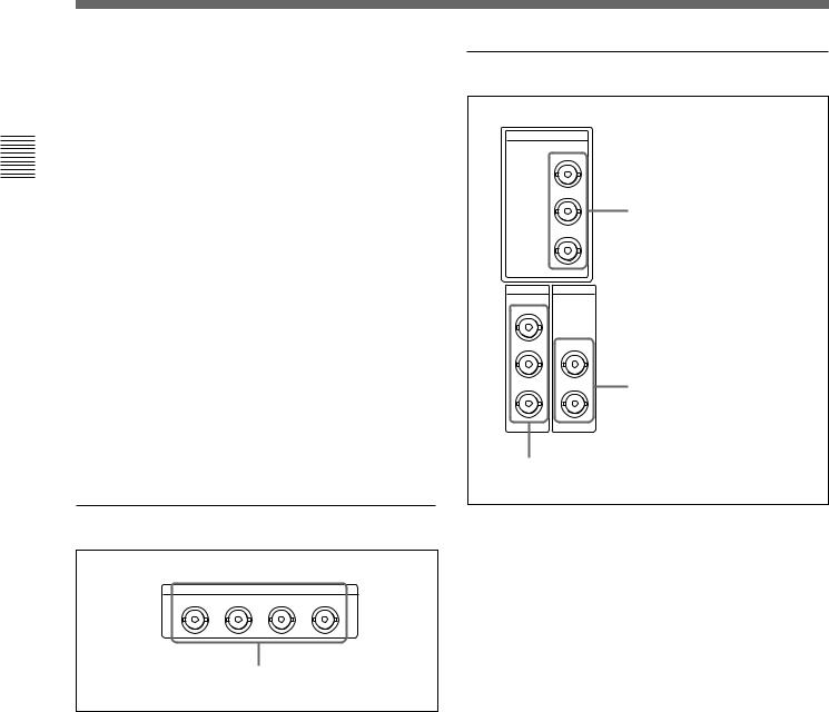
3Digital audio output section
AUDIO OUTPUT(AES/EBU)
CH1/2 |
CH3/4 |
CH5/6 |
CH7/8 |
AUDIO OUTPUT (AES/EBU) connectors
AUDIO OUTPUT (AES/EBU) connectors (BNC type)
Output a maximum of 4 sets (8 channels: CH1/2, CH3/4, CH5/6, CH7/8) of AES/EBU format digital audio signals.
4 Digital signal output section
HDSDI
|
OUTPUT |
|
|
1 |
|
|
2 |
|
|
|
1 HDSDI OUTPUT connectors |
|
3(SUPER) |
|
SDI |
SDTI |
|
OUTPUT |
OUTPUT |
|
1 |
|
|
2 |
1 |
|
|
|
|
3(SUPER) |
2 |
2 SDTI OUTPUT connectors |
|
|
3 SDI OUTPUT connectors
1 HDSDI (HD Serial Digital Interface) OUTPUT connectors (BNC type)
These connectors output HD format video/audio signals. When the setting of F4 (CHARA) in function menu page 4 is ON, connector 3 (SUPER) outputs a signal with superimposed time code, menu settings, alarm messages, and other text information.
2 SDTI (Serial Data Transport Interface) OUTPUT connectors (BNC type)
Output SDTI format video and audio signals.
3 SDI (Serial Digital Interface) OUTPUT connectors (BNC type)
These connectors output D1 format video/audio signals.
When the setting of F4 (CHARA) in function menu page 4 is ON, connector 3 (SUPER) outputs a signal with superimposed time code, menu settings, alarm messages, and other text information.
2-14 |
Chapter 2 Location and Function of Parts |
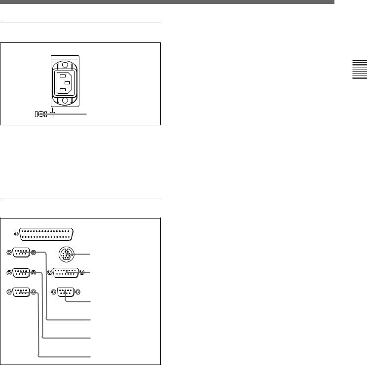
5 Power supply section
 1 AC IN connector
2 Ground terminal
1 AC IN connector
Use the optional power cord to connect this to an AC outlet.
2 Ground terminal
Connect this to ground.
6 External device connectors
REMOTE 2 PARALLEL I/O(50P)


 1 REMOTE 2 PARALLEL
I/O(50P) connector
REMOTE 1-IN(9P) CONTROL PANEL
2 CONTROL PANEL
REMOTE 1-OUT(9P) |
connector |
VIDEO CONTROL (15P) |
|
|
3 VIDEO CONTROL(15P) |
RS232C |
connector |
VIDEO CONTROL (9P) |
4 VIDEO CONTROL(9P) connector
5 REMOTE 1-IN(9P) connector
6 REMOTE 1-OUT(9P) connector
7 RS-232C connector
1 REMOTE 2 PARALLEL I/O(50P) connector (D-sub 50-pin)
Connect remote control signals from an external device.
For details, refer to the Installation Manual.
2 CONTROL PANEL connector (round type, 10pin)
In addition to the lower control panel, a similar control panel can be connected to this unit. To connect such a second control panel, use this connector. When two control panels are connected, use the PANEL SELECT switch on the switch panel (see page 2-11) to specify which control panel will control this unit.
3 VIDEO CONTROL(15P) connector (D-sub 15pin)
For remote control of the internal digital video processor, connect an optional BVR-50/50P Video Remote Control Unit.
Always power off this unit before connecting the remote control unit.
4 VIDEO CONTROL(9P) connector (D-sub 9-pin)
For remote control of the internal digital video processor, connect an optional HKDV-900 Video Remote Control Unit.
Always power off this unit before connecting the remote control unit.
5 REMOTE 1-IN(9P) connector (D-sub 9-pin)
When using this unit together with another HDCAM VTR, and a BVE-series BVE-700/900/910/2000/9000/ 9000P/9100/9100P or other editor, connect the optional 9-pin remote control cable from the other unit to this connector.
Depending on the setting of setup menu item 211, you can use this connector alone, or in a loop-through configuration with the REMOTE 1-OUT(9P) connector.
6 REMOTE 1-OUT(9P) connector (D-sub 9-pin)
This provides the loop-through output for remote control signals from the REMOTE 1-IN(9P) connector.
Depending on the setting of setup menu item 211, you can use this connector alone, or in a loop-through configuration with the REMOTE 1-IN(9P) connector.
7 RS-232C connector (D-sub 9-pin)
Use this for monitoring and diagnosis of the state of this unit from an external computer, using the ISR (Interactive Status Reporting) function.
Parts of Function and Location 2 Chapter
Chapter 2 Location and Function of Parts |
2-15 |

Parts of Function and Location 2 Chapter
2-2 Connector Panel
7 Time code output section
TIME CODE
OUT
 TIME CODE OUT connector
TIME CODE OUT connector (XLR 3-pin, male)
This outputs the playback time code.
By setting setup menu item 606, you can also output the time code from the internal time code generator locked to the playback time code.
8 Audio monitor signal output section
1 MONITOR OUTPUT R
connector
MONITOR OUTPUT
RL
2 MONITOR OUTPUT L connector
1 MONITOR OUTPUT R connector (XLR 3-pin, male)
This outputs the audio signals whose output destination was set to ‘R’ with the audio signal selection buttons in the audio control section. If multiple tracks have been set to ‘R’, the signals of those tracks are mixed for output.
2 MONITOR OUTPUT L connector (XLR 3-pin, male)
This outputs the audio signals whose output destination was set to ‘L’ with the audio signal selection buttons in the audio control section. If multiple tracks have been set to ‘L’, the signals of those tracks are mixed for output.
2-16 |
Chapter 2 Location and Function of Parts |
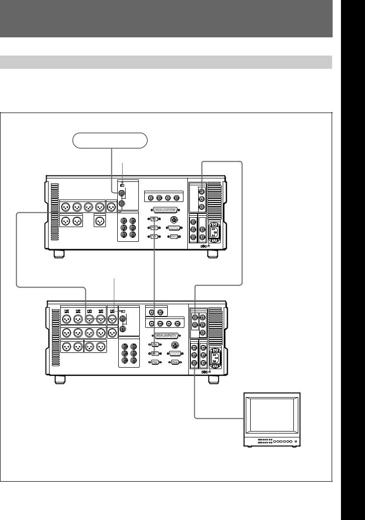
3-1 Connections to External Devices
3-1-1 Connections to Digital Devices
The following example shows the connections with an HDW-2000/M2000/M2000P unit as a recorder, with this unit used as a player.
Reference signal |
|
|
|
|
75 Ω termination |
|
|
|
|
switch: OFF |
|
|
|
|
REF. VIDEO INPUT |
HDSDI OUTPUT |
|
|
|
75Ω |
|
|
|
|
REF. VIDEO |
|
|
|
|
INPUT |
|
|
|
|
HDW-M2100/M2100P (player) |
REMOTE 1-IN(9P) |
|
|
|
|
|
|
|
|
75Ω termination |
|
|
|
|
switch: ON |
|
|
|
|
|
REMOTE |
|
|
|
REF. VIDEO INPUT |
1-OUT(9P) |
HDSDI INPUT |
|
|
75Ω |
|
|
|
|
|
SDI OUTPUT 3 |
|
|
|
HDW-2000/M2000/M2000P (recorder) |
(SUPER) |
|
|
|
|
|
|
|
|
|
|
BVM-D24 series video |
|
|
|
|
monitor |
|
|
|
|
Chapter 3 |
Preparations |
3-1 |
3 Chapter
Preparations
3 Chapter
Preparations
Preparations 3 Chapter
3-1 Connections to External Devices
3-1-2 Connecting Reference Signals
Connect reference signals as shown below.
|
SD video monitor |
HD video monitor |
75 Ω termination switch: ON |
• SDI OUTPUT |
|
• COMPOSITE |
HDSDI OUTPUT |
|
|
• COMPONENT |
75Ω |
REF. VIDEO INPUT
HDW-M2100/M2100P
Reference signal
3-2 Chapter 3 Preparations

3-2 Setup
The principal setup operations before operating this unit can be carried out using setup menus.
The setup menus of this unit comprise a basic setup menu and an extended setup menu. The contents of these menus are as follows.
Basic setup menu:
•Items relating to the hours meter
•Items relating to operation
•Items relating to menu banks
Extended setup menu:
•Items relating to control panels
•Items relating to the remote control interface
•Items relating to editing operations
•Items relating to preroll
•Items relating to tape protection
•Items relating to the time code generator
•Items relating to video control
•Items relating to audio control
•Items relating to digital processing
For detailed information about the items, except for the basic setup menu items relating to the hours meter, of these menus and how to use them, see Chapter 9 “Setup Menus”. For detailed information about menu operations relating to the hours meter, see Section 10-5-1 “Digital Hours Meter”(page 10-5).
This unit allows menu settings to be saved in what are termed “menu banks.” Saved sets of menu settings can be recalled for use as required.
For more information about the menu banks, see the section “Menu bank operations (menu items B01 to B13)” (page 9-5) .
Preparations 3 Chapter
Chapter 3 Preparations |
3-3 |
Preparations 3 Chapter
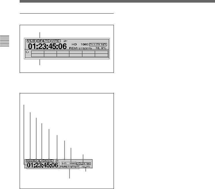
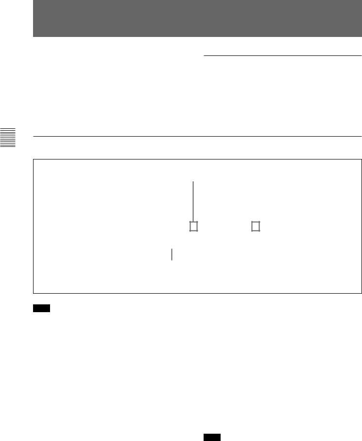
3-3 Superimposed Character Information
When the function menu item CHARA is set to ON, the video signal output from the HDSDI OUTPUT 3 (SUPER) connector, SDI OUTPUT 3 (SUPER) connector, or COMPOSITE VIDEO OUTPUT 3 (SUPER) connector contains superimposed character information, including time code, menu settings, and alarm messages.
Adjusting the character display
You can adjust the position, size and type of the superimposed characters using setup menu items 002, 003, 005, 009, and 011.
For details, see Section 9-3 “Items in the Basic Setup Menu” (page 9-7).
Information displayed
|
|
1Type of time data |
2Time code reader drop frame mark |
||||||||||||||||||||||||
|
|
|
|
|
|
|
|
|
|
|
|
|
|
|
(for 59.94i, 29.97PsF mode only) |
||||||||||||
|
|
|
|
|
|
|
|
Time data |
|
|
|
|
|
|
|
|
|
|
|
|
|
|
|
||||
|
|
|
|
|
|
|
|
|
|
|
|
|
|
|
|
|
|
|
|
|
3VITC field mark |
||||||
|
|
|
|
|
|
|
|
|
|
|
|
|
|
|
|
|
|
|
|
|
|
|
|
|
|
|
|
|
|
|
|
|
|
|
|
|
|
|
|
|
|
|
|
|
|
|
|
|
|
|
|
|
|
|
|
|
T |
C |
R |
. |
|
2 |
3 |
: |
5 |
9 |
. |
4 |
0 |
. |
1 |
8 |
* |
|
|
||||||||
|
|
|
|
|
|
|
|
|
|
|
|
|
|
|
|
|
|
|
|
|
|
|
|
|
|||
|
|
|
|
|
|
|
|
|
|
|
|
|
|
|
|
|
|
|
|
|
|
|
|
|
|
|
|
|
|
|
S |
H |
U |
T |
T |
L |
E |
|
|
|
|
S |
T |
I |
L |
L |
|
|
|
|
|||||
|
|
|
|
|
|
|
|
|
|
|
|
|
|
|
|
|
|
|
|
|
|
|
|
|
|
|
|
|
|
|
|
|
|
|
|
|
|
|
|
|
|
|
|
|
|
|
|
|
|
|
|
|
|
|
|
4Operation mode
Note
The display shown above corresponds to the factory default settings of the unit.
Changing the setting of setup menu item 005 allows different time data to be displayed in the lower line of the display.
For details, see Section 9-3 “Items in the Basic Setup Menu” (page 9-7).
1 Type of time data
Display |
Meaning |
CTL |
CTL counter data |
TCR |
LTC reader time code |
|
|
UBR |
LTC reader user’s bits |
|
|
TCR. |
VITC reader time code |
|
|
UBR. |
VITC reader user’s bits |
|
|
IN |
IN point |
|
|
OUT |
OUT point |
|
|
AI |
Audio IN point |
|
|
AO |
Audio OUT point |
|
|
DUR |
Duration between any two of the four edit |
|
points (IN, OUT, audio IN, audio OUT) |
|
|
Note
If the time data or user’s bits cannot be read correctly, they will be displayed with an asterisk. For example, “T*R”, “U*R”, “T*R.” or “U*R.”.
3-4 Chapter 3 Preparations

2 Time code reader drop frame mark (for 59.94i, 29.97PsF mode only)
“.”: Indicates drop frame mode “:”: Indicates non-drop-frame mode
3 VITC field mark
“” (blank): Fields 1 and 3 (for 59.94i, 29.97PsF mode) or fields 1, 3, 5 and 7 (for 50i, 25PsF mode)
“* ”: Fields 2 and 4 (for 59.94i, 29.97PsF mode) or fields 2, 4, 6 and 8 (for 50i, 25PsF mode)
4Operation mode
The field is divided into three blocks, A, B and C.
•Block A displays the operation mode.
•Block B displays the servo lock status or tape speed.
•Block C displays a  mark to indicate an edit section during automatic editing.
A |
B |
C |
Display |
|
Operation mode |
|
|
|
Block A |
Block B |
|
|
|
|
TAPE UNTHREAD |
Cassette is not loaded. |
|
|
|
|
STANDBY OFF |
Standby off mode |
|
|
|
|
T.RELEASE |
|
Tape tension released |
|
|
|
STOP |
|
Stop mode |
|
|
|
F.FWD |
|
Fast forward mode |
|
|
|
REW |
|
Rewind mode |
|
|
|
PREROLL |
|
Preroll mode |
|
|
|
PLAY |
|
Playback mode (servo |
|
|
unlocked) |
|
|
|
PLAY |
LOCK |
Playback mode (servo locked) |
|
|
|
PLAY |
Variation |
Capstan override mode (see |
|
from normal |
page 4-4) |
|
speed (%) |
|
JOG |
STILL |
A still picture in jog mode |
|
|
|
JOG |
FWD |
Jog mode in forward direction |
|
|
|
JOG |
REV |
Jog mode in reverse direction |
|
|
|
SHUTTLE |
(Speed) |
Shuttle mode |
|
|
|
VAR |
(Speed) |
Variable speed mode |
|
|
|
DMC |
(Speed)a) |
DMC playback speed |
D-PREV |
(Speed)a) |
DMC editing preview mode |
D-EDIT |
(Speed)a) |
DMC editing mode |
DMC-SPD |
(Speed) |
DMC initial speed setting |
|
|
|
PLY-SPD |
Variation |
Tape speed override mode |
|
from normal |
(when “TSO” is selected in |
|
speed |
setup menu item 111) |
|
|
|
a) Initial speed settings or stored speed settings
Preparations 3 Chapter
Chapter 3 Preparations |
3-5 |

Preparations 3 Chapter
3-4 Cassettes
3-4-1 Cassette Types
This unit uses the following HDCAM cassettes for playback.
HDCAM cassettes
Small cassettes BCT-6HD/12HD/22HD/32HD/40HD
Large cassettes BCT-34HDL/64HDL/94HDL/124HDL
The unit can also play back the following cassettes.
•Digital Betacam cassettes
•MPEG IMX cassettes
•Betacam SX cassettes
•Betacam SP cassettes (metal tape)
•Betacam cassettes (oxide tape)
2Check the following points, then insert the cassette in the orientation shown in the figure.
•Check that message “ERR-10” is not shown in the time data/menu display section.
•Check that there is no slack in the tape.
The cassette is drawn into the unit, and the STANDBY and STOP buttons light.
If message “ERR-10” appears in the time data/menu display section, there is moisture condensation in the unit.
Removing slack from the tape
Press in one of the reels with a finger, and turn gently in the direction shown by the arrows until there is no slack in the tape.
3-4-2 Inserting and Ejecting
Cassettes
It is not possible to insert or eject a cassette unless the unit is powered on.
Inserting a cassette
|
EJECT button |
|
1 |
|
|
|
|
2 |
|
|
Small cassette |
|
|
Large cassette |
PREROLL |
|
|
|
|
STANDBY |
|
|
STANDBY button |
REW |
PLAY F FWD |
STOP |
|
|
STOP button |
1 Turn the POWER switch on. |
||
Ejecting a cassette
Press the EJECT button.
Note
Ejecting is a local operation. It is not possible to eject a cassette in another unit by remote control.
If the tape slacks inside the unit, pressing the EJECT button may not eject the cassette. For information about how to remove the cassette in such a case, refer to the Installation Manual.
3-6 Chapter 3 Preparations
 Loading...