


 Loading...
Automation and Drives - SCE
Training Document
for
Comprehensive Automation Solutions
Totally Integrated Automation (T I A)
MODULE H01
Frequency Converter SINAMICS G120
on the
PROFIBUS DP and PROFINET
T I A Training Document |
Page 1 of 147 |
Module |
|
H01 |
|
Issued: 02/2008 |
Frequency Converter SINAMICS G120 on PROFIBUS DP and PROFINET |
|

Automation and Drives - SCE
This document has been written by Siemens AG for training purposes for the project entitled "Siemens Automation Cooperates with Education (SCE)".
Siemens AG accepts no responsibility for the correctness of the contents.
Transmission, use or reproduction of this document is only permitted within public training and educational facilities. Exceptions require the prior written approval by Siemens AG (Michael Knust michael.knust@siemens.com).
Offenders will be liable for damages. All rights, including the right to translate the document, are reserved, particularly if a patent is granted or utility model is registered.
We would like to thank the following: Michael Dziallas Engineering, the teachers at vocational schools, and all others who helped to prepare this document.
T I A Training Document |
Page 2 of 147 |
Module |
|
H01 |
|
Issued: 02/2008 |
Frequency Converter SINAMICS G120 on PROFIBUS DP and PROFINET |
|

|
|
Automation and Drives - SCE |
|
|
|
|
PAGE |
1. |
preface |
.......................................................................................................................................................... |
6 |
2. |
notes on .....................................................................................................using the CPU 315F-2 PN/DP |
9 |
|
3. |
notes on ....................................................................using the frequency converter SINAMICS G120 |
10 |
|
3.1 Description ......................................................................of the Frequency Converter SINAMICS G120 |
10 |
||
3.2 Configuring .......................................................................................the Drive with the Software SIZER |
16 |
||
3.3 Safety ............................................................................................................Precautions and Warnings |
28 |
||
3.4 Connecting ..........................................................................the Frequency Converter SINAMICS G120 |
32 |
||
|
3.4.1 .................................................................................................... |
Connecting the Power Module |
32 |
|
3.4.2 ......................................... |
Block Diagrams for the Control Units CU240S DP and CU240S PN |
33 |
|
3.4.3 ................................................................... |
Setting the Frequency Setpoints with DIP Switches |
36 |
|
3.4.4 ................................................................................ |
Settings for the Encoder with DIP Switches |
36 |
|
3.4.5 ................................................................... |
Setting the PROFIBUS Address with DIP Switches |
36 |
|
3.4.6 ................................................................................................................... |
PROFIBUS Interface |
37 |
|
3.4.7 ................................................................................................................... |
PROFINET Interface |
37 |
3.5 Starting ..........................................................................Up the Frequency Converter SINAMICS G120 |
38 |
||
|
3.5.1 .......................................................................... |
Startup Using the Basic Operator Panel (BOP) |
40 |
|
3.5.1.1 ..................................................................... |
Function Keys of the Basic Operator Panel (BOP) |
41 |
|
3.5.1.2 .................................................... |
Parameters that are visible/Parameters that can be changed |
42 |
|
3.5.1.3 ........................................................................................................................ |
BICO Technology |
44 |
|
3.5.1.4 ..................................................... |
Changing Parameters with the Basic Operator Panel (BOP) |
46 |
|
3.5.1.5 ............................................................................ |
Starting Performance of the SINAMICS G120 |
48 |
|
3.5.1.6 .............................................................................................................. |
Reset to Factory Setting |
49 |
|
3.5.1.7 ..................................................................... |
Quick Commissioning for V/f Control, for example |
50 |
|
3.5.2 .................................................. |
Startup with the Software STARTER using the Connection Kit |
52 |
|
3.5.3 ............................................................................... |
Startup with the Micro Memory Card (MMC) |
72 |
|
3.5.3.1 ....................................................... |
Manual Parameter Upload from the Converter to the MMC |
72 |
|
3.5.3.2 ...................................................... |
Manual Parameter Download from a MMC to the Converter |
73 |
3.6 |
Exercises .................................................................................................................................................. |
74 |
|
4. |
Starting ..........................................Up the frequency converter SINAMICS G120 on the PROFIBUS |
75 |
|
5. |
starting ..........................................up the frequency converter SINAMICS G120 on the PROFINET |
105 |
|
6. |
CONTROL ..........................PROGRAM 'BUCKET ELEVATOR’ ON THE PROFIBUS DP/PROFINET |
134 |
|
6.1 |
Assigning ..........................................................................the Process Data for the SINAMICS G120 |
134 |
|
|
6.1.1 ........................................................................................................... |
The Control Word (STW) |
134 |
|
6.1.2 ............................................................................................................ |
The Status Word (ZSW) |
136 |
|
6.1.3 ......................................................................................................... |
The Main Setpoint (HSW) |
137 |
|
6.1.5 ............................................... |
Arrangement of the Request Message in Double Word Format |
138 |
|
6.1.6 .............................................. |
Arrangement of the Response Message in Doubleword Format |
138 |
6.2 Assignment List and Symbol Table |
........................................................................................................ |
139 |
T I A Training Document |
Page 3 of 147 |
Module |
|
H01 |
|
Issued: 02/2008 |
Frequency Converter SINAMICS G120 on PROFIBUS DP and PROFINET |
|

|
|
Automation and Drives - SCE |
6.3 |
Generating the Data Block for the Request Message............................................................................ |
141 |
6.4 |
Generating the Data Block for the Response Message......................................................................... |
143 |
6.5 |
Generating Function FC10 to Control the Bucket Elevator.................................................................... |
144 |
6.6 |
Generate Organization Block OB1 for Controlling the Bucket Elevator................................................. |
146 |
6.7 |
Load the blocks for controlling the bucket elevator to the CPU 315-2DP.............................................. |
147 |
T I A Training Document |
Page 4 of 147 |
Module |
|
H01 |
|
Issued: 02/2008 |
Frequency Converter SINAMICS G120 on PROFIBUS DP and PROFINET |
|
Automation and Drives - SCE
The following symbols are provided as a guide through Module H01:
Information
Programming
Sample Exercise
Notes
T I A Training Document |
Page 5 of 147 |
Module |
|
H01 |
|
Issued: 02/2008 |
Frequency Converter SINAMICS G120 on PROFIBUS DP and PROFINET |
|

Automation and Drives - SCE
1.PREFACE
In terms of its contents, Module H01 is part of the teaching unit entitled ’Frequency Converter at SIMATIC S7’.
|
|
|
|
Fundamentals of |
|
|
|
|
|
|
|
|||
|
|
|
|
STEP 7 Programming |
|
|
|
|
|
|
|
|||
|
|
|
2 to 3 days |
Modules A |
|
|
|
|
||||||
|
|
|
|
|
|
|
|
|
|
|
|
|||
|
|
|
|
|
|
|
|
|
|
|||||
|
|
|
Additional Functions of STEP 7 |
|
|
|
|
|||||||
|
|
|
|
|
Plant Simulation with |
|||||||||
|
|
|
|
Programming |
|
|
|
|
|
|||||
|
|
|
|
|
|
|
|
|
SIMIT SCE |
|||||
|
|
|
2 to 3 days |
Modules B |
|
|
|
|
||||||
|
|
|
|
|
|
|
1 to 2 days Modules G |
|||||||
|
|
|
|
|
|
|
|
|
|
|
|
|
||
|
|
|
|
|
|
|
|
|
|
|
|
|
|
|
|
|
|
|
|
|
|
|
|
|
|
|
|
|
|
Programming |
|
|
Industrial Fieldbus |
|
|
|
Process |
|
||||||
Languages |
|
|
|
Systems |
|
|
|
Visualization |
|
|||||
2 to 3 days Modules C |
|
|
2 to 3 days Modules D |
|
|
|
2 to 3 days Modules F |
|
||||||
|
|
|
|
|
|
|
|
|
|
|
|
|
|
|
|
|
|
|
|
|
|
|
|
||||||
|
Frequency Converter |
|
|
|
|
IT Communication |
|
|
||||||
|
at SIMATIC S7 |
|
|
|
|
|
with SIMATIC S7 |
|
||||||
|
2 to 3 days Modules H |
|
|
|
2 to 3 days Modules E |
|
||||||||
|
|
|
|
|
|
|
|
|
|
|
|
|
|
|
Learning Objective:
In Module H01, the reader learns how the frequency converter SINAMICS G120 is started up together with the CPU 315F-2 PN/DP on PROFIBUS DP as well on PROFINET. Module H01 shows the method in principle, using a brief example for each the PROFIBUS and the PROFINET.
Prerequisites:
To successfully work through Module H01, the following knowledge is assumed:
•Knowledge in handling Windows
•Fundamentals of PLC programming with STEP 7 (for example, Module A3 - 'Startup’ PLC Programming with STEP 7)
•Fundamentals of PROFIBUS DP (for example, Appendix IV – Fundamentals of Fieldbus
Systems with SIMATIC S7-300)
●Fundamentals of network engineering (for example, Appendix V - Basics of Network Engineering)
|
Preface |
Notes |
Startup with PROFIBUS |
Startup with PROFINET |
Program Example |
|
|
|
|
|
|
T I A Training Document |
|
Page 6 of 147 |
|
Module |
|
|
|
|
H01 |
|
|
Issued: 02/2008 |
|
Frequency Converter SINAMICS G120 on PROFIBUS DP and PROFINET |
|||

Automation and Drives - SCE
Hardware and Software Required
1.PC, operating system Windows 2000 Professional starting with SP4/XP Professional starting with SP1/Server 2003 with 600MHz and 512RAM, free hard disk storage approx 650 to 900 MB, MS Internet Explorer 6.0, and network card
2.Software STEP 7 V 5.4
3.Startup Software STARTER V4.1
4.Configuring Software SIZER V2.8
5.MPI for the PC (such as PC Adapter USB)
6.PLC SIMATIC S7-300 with CPU 315F-2 PN/DP and at least one digital input and output module
Sample configuration:
-Power unit: PS 307 2A
-CPU: CPU 315F-2 PN/DP
-Digital inputs: DI 16x DC 24V
-Digital Outputs: DO 16x DC 24V / 0.5 A
7.Frequency Converter SINAMICS G120 with:
-Control Unit CU240S DP
-Control Unit CU240S PN
-Basic Operator Panel BOP
-PC Connection Kit
-Asynchronous Motor
8.Ethernet connection between PC, CPU 315F-2 PN/DP and SINAMICS G120 with CU240S PN
9.PROFIBUS cable with 2 PROFIBUS connectors for connecting the CPU 315F-2 PN/DP and the SINAMICS G120 with CU240S DP
|
Preface |
Notes |
Startup with PROFIBUS |
Startup with PROFINET |
Program Example |
|
|
|
|
|
|
T I A Training Document |
|
Page 7 of 147 |
|
Module |
|
|
|
|
H01 |
|
|
Issued: 02/2008 |
|
Frequency Converter SINAMICS G120 on PROFIBUS DP and PROFINET |
|||
Automation and Drives - SCE
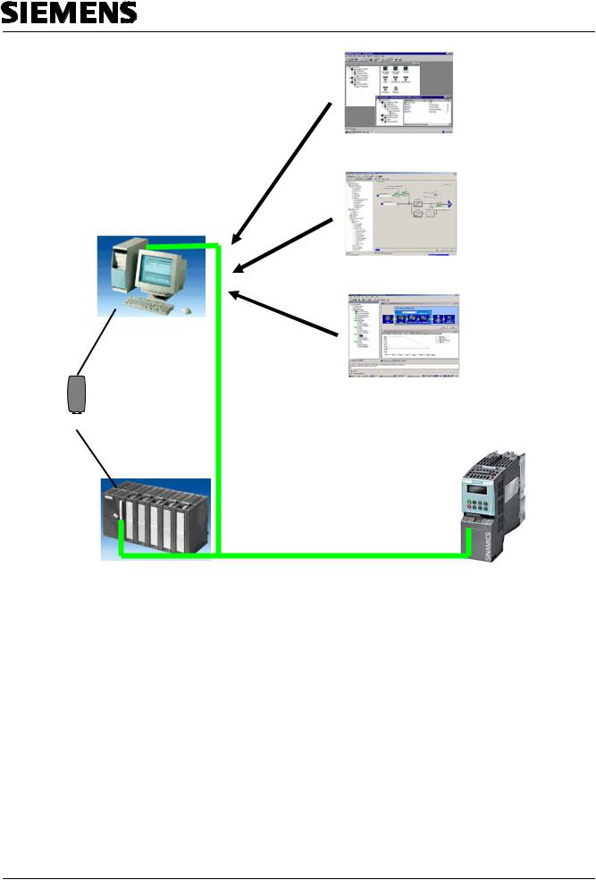
2 STEP 7
3 STARTER
1 PC
4 SIZER


 5 PC Adapter USB
9 PROFIBUS Cable
|
|
|
|
|
|
|
|
|
|
|
|
|
|
|
|
|
|
|
|
|
|
|
|
8 Ethernet Connection |
|||
|
|
|
||||
6 SIMATIC S7-300 with |
7 Frequency Converter |
|||||
CPU 315F-2 PN/DP |
||||||
SINAMICS G120 with: |
||||||
|
|
|
||||
|
|
|
- Control Unit CU240S DP |
|||
|
|
|
- Control Unit CU240S PN |
|||
|
|
|
- Basic Operator Panel BOP |
|||
|
|
|
- PC Connection Kit |
|||
|
|
|
- Asynchronous Motor |
|||
|
Preface |
Notes |
Startup with PROFIBUS |
Startup with PROFINET |
Program Example |
|
|
|
|
|
|
T I A Training Document |
|
Page 8 of 147 |
|
Module |
|
|
|
|
H01 |
|
|
Issued: 02/2008 |
|
Frequency Converter SINAMICS G120 on PROFIBUS DP and PROFINET |
|||

Automation and Drives - SCE
2.NOTES ON USING THE CPU 315F-2 PN/DP
The CPU 315F-2 PN/DP is a CPU that is shipped with two integrated interfaces.
-The first interface is a combined MPI/PROFIBUS-DP interface that can be used on the PROFIBUS DP as Master or as Slave to connect distributed peripherals/fieldbus devices with very fast response timing.
Moreover, the CPU can be programmed here by means of the MPI or also PROFIBUS DP
-The second interface is an integrated PROFINET interface.
It allows for using the CPU as a PROFINET IO controller to operate distributed peripherals on the PROFINET. The CPU can be programmed by means of this interface also!
-At both interfaces, frequency converters and also fault-tolerant IO devices can be used.
Notes:
-In Module H01, the CPU 315F-2 PN/DP is used as IO controller on the PROFINET and as master on the PROFIBUS DP.
-To operate this CPU, a micro memory card is required!
-The addresses of the input and output modules can be parameterized in the case of this CPU.
|
Prefacet |
Notes |
Startup with PROFIBUS |
Startup with PROFINET |
Program Example |
|
|
|
|
|
|
T I A Training Document |
|
Page 9 of 147 |
|
Module |
|
|
|
|
H01 |
|
|
Issued: 02/2008 |
|
Frequency Converter SINAMICS G120 on PROFIBUS DP and PROFINET |
|||
Automation and Drives - SCE
3.NOTES ON USING THE FREQUENCY CONVERTER SINAMICS G120
Below, important information is provided about starting up and operating the SINAMICS G120. However, we do not claim that this information is comprehensive, and refer to the following technical documentation:
-Getting Started
-Operating Instructions
-Installation Manual
-Function Manual
-List Manual
-Product Information
These documents are available on the Service and Support Internet page: - http://support.automation.siemens.com
There, you can download the current version of these documents, free of charge.
3.1Description of the Frequency Converter SINAMICS G120
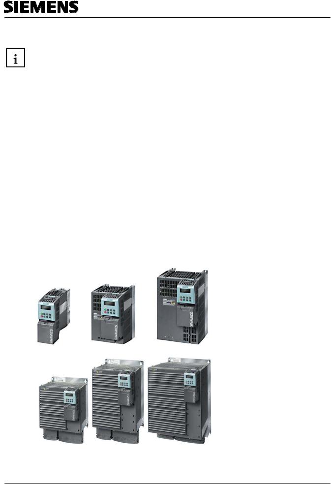
The converter SINAMICS G120 is used for more accurate and efficient closed loop speed control of three phase motors.
The SINAMICS G120 is available in different device versions ((size FSA to FSF) in the performance range of 0.37 KW to 90 KW. It is suitable for a large number of drive solutions
•As a universal drive in industry and trade
•In different branches such as automotive, textile, printing, and chemical
•For general applications, such as conveyor systems
|
Preface |
Notes |
Startup with PROFIBUS |
Startup with PROFINET |
Program Example |
|
|
|
|
|
|
T I A Training Document |
|
Page 10 of 147 |
|
Module |
|
|
|
|
H01 |
|
|
Issued: 02/2008 |
|
Frequency Converter SINAMICS G120 on PROFIBUS DP and PROFINET |
|||
Automation and Drives - SCE
General Features of the SINAMICS G120
Flexibility through modularity for a future proof drive concept:
•Tailored to the customer, selectable and scalable
•Modules can be exchanged live (hot swap)
•Insertable terminals
•Easily exchanged; very maintenance-friendly
●Because of the safety functionalties, less effort when integrating drives into safety oriented machines are plants
•Capable of communicating with PROFIBUS and PROFINET with PROFIdrive Profile 4.0
•Reduction of interfaces
•Plant-wide engineering
•Simple handling
•Increased robustness and longer life because of an innovative cooling concept and painted electronic modules
•Simple device exchange and time-saving copying of parameters by means of the Basic Operator Panel (BOP) or the optional memory card MMC
•Non-volatile storage of the parameter settings –either in the EEPROM of the CU or on an MMC
•Low noise motor operation because of high pulse frequency
•Compact design that saves space
•Software parameters for simple adaptation to 50Hz or 60Hz motors (IEC or NEMA motors)
•2/3 wire control (static/pulsed signals) for universal control by means of the digital inputs
•Signal wiring by means of binector/connector (BICO) technology possible
•Different data sets can be selected
•Robust, non-sensitive EMC configuration
•LED status display at the control unit
•Built-in brake chopper for dynamic braking
•Fast Current Limitation (FCL), to prevent undesired disconnections during operation
•Engineering and startup with standard engineering tools such as SIZER and STARTER ensure fast configuring and simple startups
•Globally certified according to CE, UL, cUL, c-tick, and Safety Integrated according to IEC 61508 SIL 2
•With PM250 or PM260 capability of energy regeneration and regenerative breaking
|
Preface |
Notes |
Startup with PROFIBUS |
Startup with PROFINET |
Program Example |
|
|
|
|
|
|
T I A Training Document |
|
Page 11 of 147 |
|
Module |
|
|
|
|
H01 |
|
|
Issued: 02/2008 |
|
Frequency Converter SINAMICS G120 on PROFIBUS DP and PROFINET |
|||

Automation and Drives - SCE
•Special Functions for Startup
•Resetting of the parameters to the plant setting
•Quick commissioning
•Calculation of motor/control data
•Motor data identification
Restart Functions
•Setpoint channel can be set
•Ramp generator can be set
•Inching mode
•Free function blocks (FFB)
•Fast free function blocks (fast FFBs)
•Positioning deceleration ramp
•Automatic restart (WEA)
•Flying restart allows for starting the converter while the motor is rotating
•Current limiting
•Slip compensation so the speed of a drive does not change depending on the load
•Motor holding brake (MHB)
Control Functions
•V/f control with different curves
•Vector control without encoder (SLVC) for speed and torque
•Vector control with encoder (VC) for speed and torque
Protection Functions
•Motor protection functions
•Converter protection functions
•Plant/system protection functions
Failsafe Functions (only for CU240S DP-F)
•Safely switched off moment of force (STO)
•Safe stop 1 (SS1)
•Safely limited speed (SLS)
•Safe break control (SBC)
•The failsafe functions can be triggered by means of digital outputs (FDI0A … FDI1B) or PROFIsafe.
.
|
Preface |
Notes |
Startup with PROFIBUS |
Startup with PROFINET |
Program Example |
|
|
|
|
|
|
T I A Training Document |
|
Page 12 of 147 |
|
Module |
|
|
|
|
H01 |
|
|
Issued: 02/2008 |
|
Frequency Converter SINAMICS G120 on PROFIBUS DP and PROFINET |
|||

Automation and Drives - SCE
Modularity
SINAMICS G120 is a modular converter system that consists of different functional units. The two basic building blocks are the Control Unit (CU) and the Power Module (PM).
The Control Unit controls and monitors the power module and the connected motor in several control modes that can be selected. It supports communication with a local or central controller as well as with monitoring devices. In addition to controlling, other functions are available that can be adapted to the respective application through corresponding parameter assignment.
The control units are available in the following types:
●Standard CUs (CUs without safety oriented functions)
– CU240S
– CU240S DP like the CU240S but with PROFIBUS DP interface (PROFIdrive Profile 4.0)
– CU240S PN like the CU240S but with PROFINET interface (PROFIdrive Profile 4.0)
●CUs with safety oriented functions
– CU240S DP-F like the CU240S DP but with integrated safety oriented functions
The Power Module provides the motor with a performance range of 0.37 KW to 90 KW. The control unit controls the power module by means of a micro processor. For highly reliable and flexible motoring, the most modern IGBT technology with pulse width modulation is used. Comprehensive protection functions provide a high measure of protection for the power module and the motor.
The power modules are available in the following types:
● Power Module PM240 with DC braking functions, supply voltage 3 AC 400V
The PM240 has an integrated brake chopper, and is designed for drives without power recovery for the network. Possible regenerative energy is converted into heat by means of brake resistors that are connected externally.
●Power Module PM250 with energy regeneration capability, supply voltage 3 AC 400V
●Power Module PM260 with energy regeneration capability, supply voltage 3 AC 690V Power modules PM250 and PM260 have an innovative circuit concept which makes line
commutated power recovery possible. This innovation allows for returning regenerative energy to the network, and thus saves energy.
Control units and power modules can be combined into any configuration. In this training document, the control units CU240S DP and CU240S PN are described, together with the Power Module PM240.
|
Preface |
Notes |
Startup with PROFIBUS |
Startup with PROFINET |
Program Example |
|
|
|
|
|
|
T I A Training Document |
|
Page 13 of 147 |
|
Module |
|
|
|
|
H01 |
|
|
Issued: 02/2008 |
|
Frequency Converter SINAMICS G120 on PROFIBUS DP and PROFINET |
|||

Automation and Drives - SCE
Optional Additional Components
Numerous supplementary components are available for the SINAMICS G120, such as:
•Basic Operator Panel (BOP)
With the Basic Operator Panel BOP -that can be inserted in the control unitdrives can be started up, current operations can be monitored, and individual parameters can be set. In addition, the BOP provides a function for copying parameters in a time-saving way.
•PC Converter – Connecting Set (PC Connection Kit)
This kit is used for controlling and starting up a converter directly from the PC, provided the corresponding software (STARTER) is installed. The startup tool STARTER on CD ROM is included in the PC Converter Connection Set.
•Brake Relay
With the brake relay, you can set up a connection between the power module and an electromechanical motor brake. Thus, the motor brake can be controlled directly with the control unit.
•Safe Brake Relay
With the safe brake relay, you can establish a connection between the power module and an electrical-mechanical motor brake. Thus, safe brake controls can be implemented directly with the control unit according to EN 954-1 Safety Category 3 and IEC 61508 SIL 2.
•MicroMemoryCard (MMC)
On the MMC, you can store the parameter assignment of the converter. If servicing is required, the plant is immediately ready after the converter is replaced and the data is copied back from the memory card. The associated slot is located on top of the control unit.
•Line-Side Power Components
•Network Filters Class A and B
With an additional network filter, the Power Module PM240 attains a higher radio interference class.
•Line Reactors
A line reactor is needed if the system fault level is high, for two reasons: on the one hand, to protect the converter itself from harmonic currents and overloads, on the other hand to limit system perturbation to the permissible values.
|
Preface |
Notes |
Startup with PROFIBUS |
Startup with PROFINET |
Program Example |
|
|
|
|
|
|
T I A Training Document |
|
Page 14 of 147 |
|
Module |
|
|
|
|
H01 |
|
|
Issued: 02/2008 |
|
Frequency Converter SINAMICS G120 on PROFIBUS DP and PROFINET |
|||

Automation and Drives - SCE
•Intermediate Circuit Components
•Brake Resistors
By means of the braking resistors, excess energy of the intermediate circuit is reduced. The braking resistors are intended for use with the PM240. It has an integrated brake chopper (electronic switch).
•Power Components on the Output Side
They allow for longer, shielded motor cable lengths for operation with output reactors or LC filters and sinusoidal filters; in addition, the life of the motor is extended.
•Output Reactors
Output reactors reduce the voltage load on the motor winding. At the same time, the capacitive charge reversal currents are reduced which additionally strain the power unit when longer motor cables are used.
•LC Filters and Sinusoidal Filters
LC filters and sinusoidal filters limit the voltage rise rate and the capacitive charge reversal currents that usually occur at converter operation. Output reactors are then no longer needed.
Safety Integrated
The converter built-in units SINAMICS G120 offer variants of safety oriented applications. All power modules are already fail-safe units. If a power module is combined with a corresponding failsafe control unit, this drive becomes a Safety Integrated Drive.
The failsafe frequency converter SINAMICS G120 offers four safety functions, certified according to EN 954-1, Kat.3 and IEC 61508 SIL 2:
•Safe Stop 1 (SS1)
•Safely Limited Speed (SLS)
•Safe Brake Control (SBC)
•Safely switched-off torque (STO)
Innovative Cooling Concept and Painted Electronic Modules
The innovative cooling concept of the electronic module and painting the module extend its life or use considerably, and results in the following:
•Dissipation of power loss exclusively by means of the external heat sink
•Electronic modules not in the air duct
•Consistent convection cooling of the control unit
•The air flow of the fan blows exclusively through the heat sink
PROFIdrive Profile 4.0
The user data structure of the cyclical/acyclical communication channel is specified for PROFIBUS and PROFINET in the PROFIdrive Profile, Version 4.0.
The PROFIdrive Profile specifies for the converters how a master/controller can access the converters (slaves/devices) by means of cyclical or acyclical data transmission.
Note:
PROFIdrive for drive technology is standardized and described in the following document: Literature: [P5] PROFIdrive Profile Drive Technology
|
Preface |
Notes |
Startup with PROFIBUS |
Startup with PROFINET |
Program Example |
|
|
|
|
|
|
T I A Training Document |
|
Page 15 of 147 |
|
Module |
|
|
|
|
H01 |
|
|
Issued: 02/2008 |
|
Frequency Converter SINAMICS G120 on PROFIBUS DP and PROFINET |
|||

Automation and Drives - SCE
3.2Configuring the Drive with the Software SIZER
The drive family SINAMICS and MICROMASTER 4 are conveniently configured with the PC tool SIZER. It provides support when configuring the hardware and firmware components needed for a drive task. SIZER includes the configuration of the entire drive system so that you can handle basic single drives as well as complex multi-axis applications.
SIZER supports all configuring steps in a guided work sequence:
•Selection of system supply
•Motor design as the result of load configuring
•Calculation of the work components
•Assembling the required accessories
•Selection of line-side and motor-side power options
The drive configuration is stored in a project. In the project, the components and functions used are represented in a tree structure, according to their assignment. The project view allows for configuring the drive systems as well as for copying, inserting, modifying drives that are already configured.
The results of a configuration are:
•List of components required
•Technical data
•Characteristic curves
•Information regarding system perturbations
•Location diagram and dimensioned diagrams
These results are displayed in a result tree, and can be used also for documentation purposes. To support the user, technological Online Help is available, providing the following:
•Detailed technical data
•Information about the drive systems and their components
•Decision criteria for selecting components
Minimum Hardware and Software Requirements are:
-PG or PC with Pentium™ II 400 MHz (Windows™ 2000)
-Pentium™ III 500 MHz (Windows™ XP)
-256 Mbyte RAM (recommended 512 Mbyte RAM)
-At least 990 Mbyte free hard disk memory
-In addition, 100 Mbyte free hard disk memory on the Windows system drive
-Monitor resolution 1024×768 pixels
-Windows™ 2000 SP2, XP Professional SP1, XP Home Edition SP1
-Microsoft Internet Explorer 5.5 SP2
|
Preface |
Notes |
Startup with PROFIBUS |
Startup with PROFINET |
Program Example |
|
|
|
|
|
|
T I A Training Document |
|
Page 16 of 147 |
|
Module |
|
|
|
|
H01 |
|
|
Issued: 02/2008 |
|
Frequency Converter SINAMICS G120 on PROFIBUS DP and PROFINET |
|||
Automation and Drives - SCE
The description below explains how a drive is configured by using Sizer. First, we generate a project and select the desired components as follows:
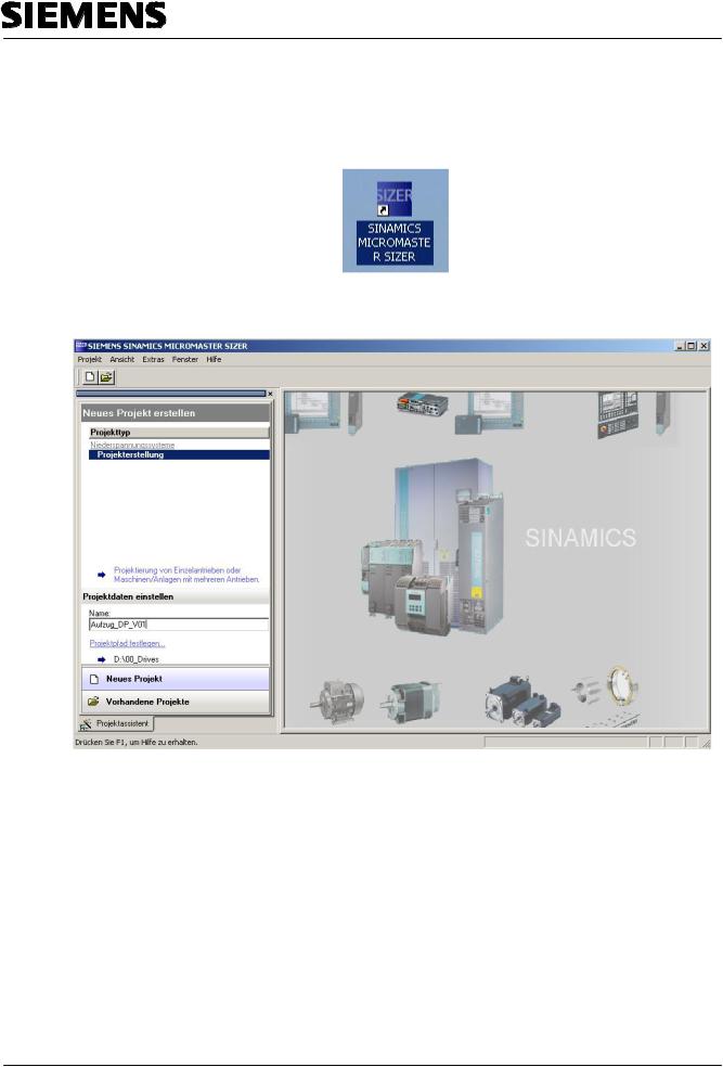
1. From the desktop, call the ’SIZER’ with a double click. (→ Sizer)
2.By double-clicking on ’Project Generation’, a new project is set up with the name ’Elevator_DP_V01’ in the project path (→ Aufzug_DP_V01 → Project generation)
|
Preface |
Notes |
Startup with PROFIBUS |
Startup with PROFINET |
Program Example |
|
|
|
|
|
|
T I A Training Document |
|
Page 17 of 147 |
|
Module |
|
|
|
|
H01 |
|
|
Issued: 02/2008 |
|
Frequency Converter SINAMICS G120 on PROFIBUS DP and PROFINET |
|||
Automation and Drives - SCE
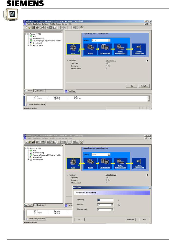
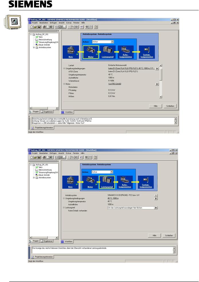
3. In the Sizer on the left, the project tree is located with the structure of the drive project; on the right, ’Workflow’ shows you the steps required to set up the drive system.
4.Now, first click on ’Network’ to view the network data. By clicking on the button ' ’, you get to the dialog for setting the voltage, the frequency, and the number of phases. (→ Network →
  → Voltage 400V → Frequency 50Hz → Number of phases 3 → OK)
|
Preface |
Notes |
Startup with PROFIBUS |
Startup with PROFINET |
Program Example |
|
|
|
|
|
|
T I A Training Document |
|
Page 18 of 147 |
|
Module |
|
|
|
|
H01 |
|
|
Issued: 02/2008 |
|
Frequency Converter SINAMICS G120 on PROFIBUS DP and PROFINET |
|||
Automation and Drives - SCE
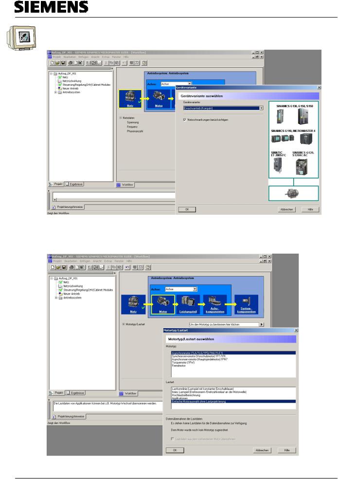
5. When selecting the ’Motor’ -the next step in 'Workflow’-, first a selection of the device variant appears. We are selecting ’Single Axis Drive (Compact)’.(→ Motor → Single Axis Drive (Compact) →OK)
6.As the motor type, we select ’Asynchronous Motor’, and for load type ’Basic motor selection without load configuring’. (→ Asynchronous motor → Basic motor selection without load configuring → OK)
|
Preface |
Notes |
Startup with PROFIBUS |
Startup with PROFINET |
Program Example |
|
|
|
|
|
|
T I A Training Document |
|
Page 19 of 147 |
|
Module |
|
|
|
|
H01 |
|
|
Issued: 02/2008 |
|
Frequency Converter SINAMICS G120 on PROFIBUS DP and PROFINET |
|||
Automation and Drives - SCE
7.After selecting ’Environmental conditions’, we now click on ' ’ to select the motor. (→
Umgebungsbedingungen → Motor  )
)
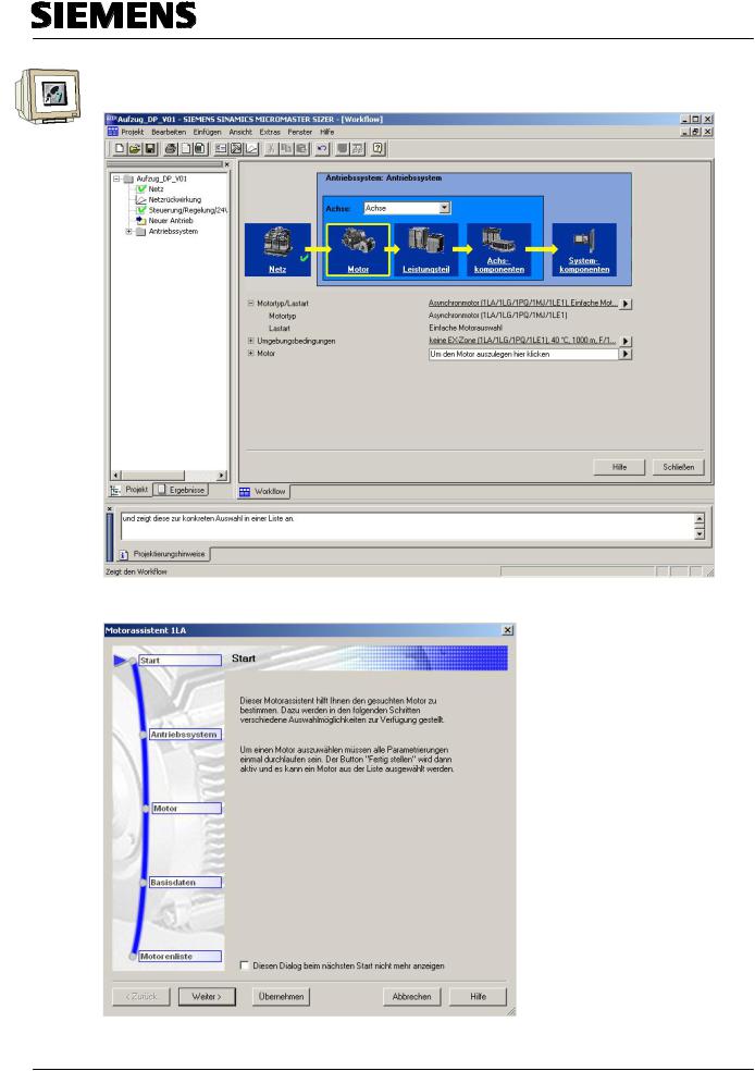
8. Then, we are starting the motor wizard 1LS by clicking on the button ’Continue’. (→ Weiter >)
|
Preface |
Notes |
Startup with PROFIBUS |
Startup with PROFINET |
Program Example |
|
|
|
|
|
|
T I A Training Document |
|
Page 20 of 147 |
|
Module |
|
|
|
|
H01 |
|
|
Issued: 02/2008 |
|
Frequency Converter SINAMICS G120 on PROFIBUS DP and PROFINET |
|||
Automation and Drives - SCE
9. First, we select the converter type ’SINAMICS G120 (PM240)’, and as control type FluxCurrentControl ’FCC with V/f’ curve (→ SINAMICS G120 (PM240) → FCC with V/f → Continue >)
10. Next, selecting additional options takes us to the order number of the power supply. (→ 1LA7053-2AA60 → Continue >)
|
Preface |
Notes |
Startup with PROFIBUS |
Startup with PROFINET |
Program Example |
|
|
|
|
|
|
T I A Training Document |
|
Page 21 of 147 |
|
Module |
|
|
|
|
H01 |
|
|
Issued: 02/2008 |
|
Frequency Converter SINAMICS G120 on PROFIBUS DP and PROFINET |
|||
Automation and Drives - SCE
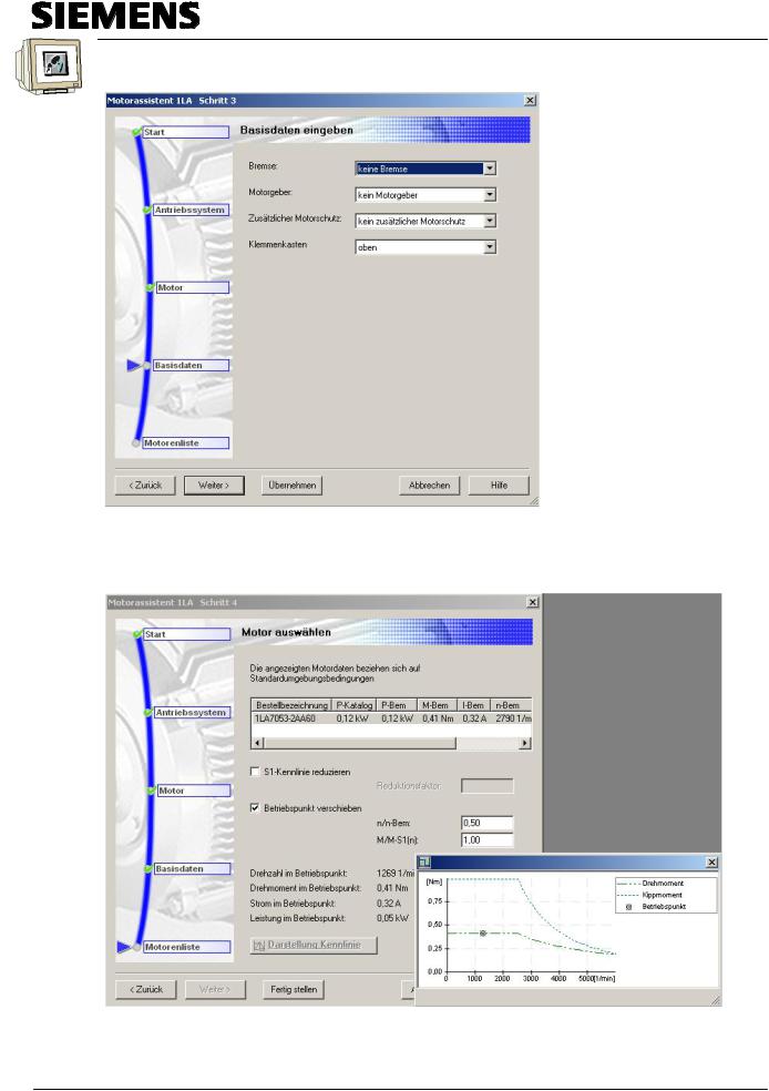
11. Now we specify whether a ’Brake’, a ’Motor encoder’ or ’additional motor protection’ is desired. Here, the position of the ’Terminal box’ is selected also. ( → Continue >)
12. After we have determined the order name in this way, we can set the operating point (using the characteristic curve) before we ’Complete’ the motor. (→ Betriebspunkt verschieben → Fertig stellen)
|
Preface |
Notes |
Startup with PROFIBUS |
Startup with PROFINET |
Program Example |
|
|
|
|
|
|
T I A Training Document |
|
Page 22 of 147 |
|
Module |
|
|
|
|
H01 |
|
|
Issued: 02/2008 |
|
Frequency Converter SINAMICS G120 on PROFIBUS DP and PROFINET |
|||
Automation and Drives - SCE
13. All data pertaining to the motor is now represented in Workflow.
14. Next, we specify the ’Power unit’. (→ Leistungsteil →  )
)
|
Preface |
Notes |
Startup with PROFIBUS |
Startup with PROFINET |
Program Example |
|
|
|
|
|
|
T I A Training Document |
|
Page 23 of 147 |
|
Module |
|
|
|
|
H01 |
|
|
Issued: 02/2008 |
|
Frequency Converter SINAMICS G120 on PROFIBUS DP and PROFINET |
|||
Automation and Drives - SCE
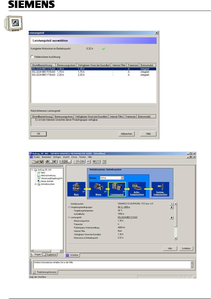
15. Based on the current setpoints and the selection/deselection for 'failsafe variant’, the power unit can now be specified (→ 6SL3224-0BE13-7UA0 → OK)
16. Details about the power unit are now shown in the Workflow.
|
Preface |
Notes |
Startup with PROFIBUS |
Startup with PROFINET |
Program Example |
|
|
|
|
|
|
T I A Training Document |
|
Page 24 of 147 |
|
Module |
|
|
|
|
H01 |
|
|
Issued: 02/2008 |
|
Frequency Converter SINAMICS G120 on PROFIBUS DP and PROFINET |
|||
Automation and Drives - SCE
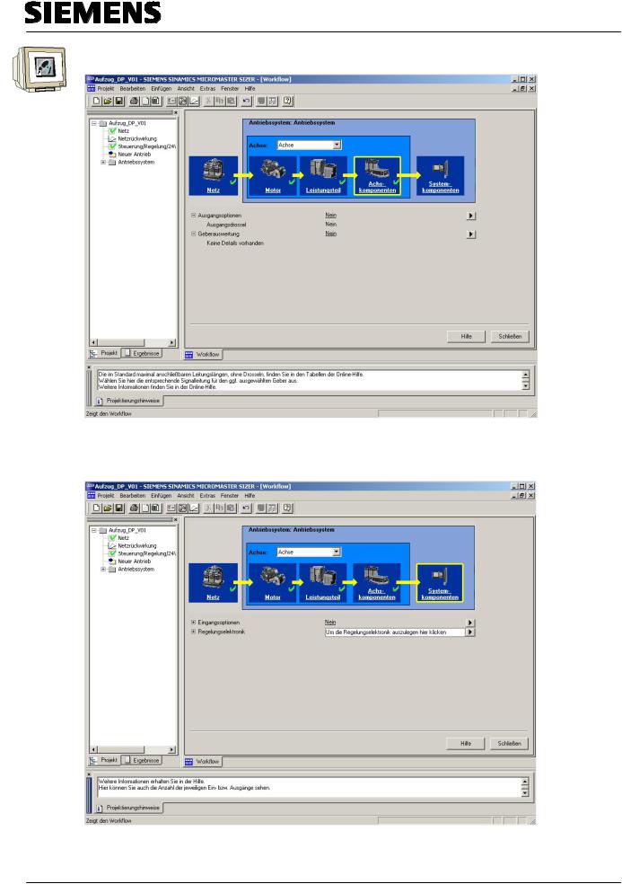
17. The ’Axis components’ such as ’Output reactor’ and ’Encoder evaluation’ are deselected here. (→ Axis components → Output options → No → Encoder evaluation → No)
18. At ’System components’, the ’Input options’ are deselected and the ’Control electronics’ are specified (→ System components → Input options → No → Control eletronics →  )
)
|
Preface |
Notes |
Startup with PROFIBUS |
Startup with PROFINET |
Program Example |
|
|
|
|
|
|
T I A Training Document |
|
Page 25 of 147 |
|
Module |
|
|
|
|
H01 |
|
|
Issued: 02/2008 |
|
Frequency Converter SINAMICS G120 on PROFIBUS DP and PROFINET |
|||
Automation and Drives - SCE
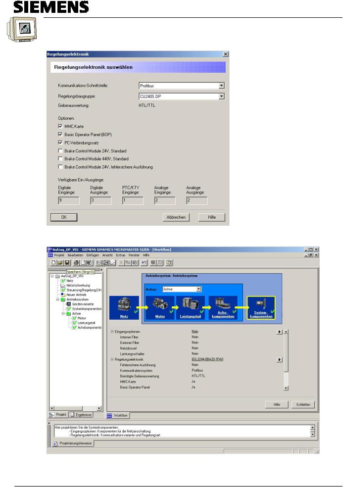
19. Regarding the control electronics, we have to select the Control Unit (CU) and its options such as ’MMC’, ’Basic Operator Panel (BOP)’ and ’PC connection set’. (→ Profibus → CU240S DP → MMC card → Basic Operator Panel (BOP)→ PC connection set → OK)
20. With the drive configuration completed, the project can be saved (→ Save)
|
Preface |
Notes |
Startup with PROFIBUS |
Startup with PROFINET |
Program Example |
|
|
|
|
|
|
T I A Training Document |
|
Page 26 of 147 |
|
Module |
|
|
|
|
H01 |
|
|
Issued: 02/2008 |
|
Frequency Converter SINAMICS G120 on PROFIBUS DP and PROFINET |
|||

Automation and Drives - SCE
21. In the results, you will see the ’Component list’, ’Technical data’, ’Characteristics’ and
’Dimensional diagrams’ for the drive project. (→ Stückliste → Technical data → Characteristics → Dimensional diagrams)
|
Preface |
Notes |
Startup with PROFIBUS |
Startup with PROFINET |
Program Example |
|
|
|
|
|
|
T I A Training Document |
|
Page 27 of 147 |
|
Module |
|
|
|
|
H01 |
|
|
Issued: 02/2008 |
|
Frequency Converter SINAMICS G120 on PROFIBUS DP and PROFINET |
|||

Automation and Drives - SCE
3.3Safety Precautions and Warnings
Prior to installing and starting up the SINAMICS G120, the following safety related guidelines and warnings have to be noted.
General
 Warning
This equipment contains dangerous voltages and controls potentially dangerous rotating mechanical parts. Non-compliance with the warnings or failure to follow the instructions contained in this manual can result in loss of life, severe personal injury or serious damage to property.
Protection in case of direct contact by means of SELV / PELV is only permissible in areas with equipotential bonding and in dry indoor rooms. If these conditions are not fulfilled, other protective measures against electric shock must be applied e.g. protective insulation.
Only suitably qualified personnel should work on this equipment, and only after becoming familiar with all safety notices, installation, operation and maintenance procedures contained in this manual. The successful and safe operation of this equipment is dependent upon its proper handling, installation, operation and maintenance.
The power supply, DC and motor terminals, the brake and thermistor cables can carry dangerous voltages even if the inverter is inoperative. Wait at least five minutes to allow he unit to discharge after switching off the line supply before carrying out any installation work.
It is strictly prohibited for any mains disconnection to be performed on the motor-side of the system; any disconnection of the mains must be performed on the mains-side of the Inverter.
When connecting the line supply to the Inverter, make sure that the terminal case of the motor is closed.
When changing from the ON to OFF-state of an operation if an LED or other similar display is not lit or active; this does not indicate that the unit is switched-off or powered-down.
The inverter must always be grounded.
Isolate the line supply before making or changing connections to the unit.
Ensure that the inverter is configured for the correct supply voltage. The inverter must not be connected to a higher voltage supply.
Static discharges on surfaces or interfaces that are not generally accessible (e.g. terminal or connector pins) can cause malfunctions or defects. Therefore, when working with inverters or inverter components, ESD protective measures should be observed.
Take particular notice of the general and regional installation and safety regulations regarding work on dangerous voltage installations (e.g. EN 50178) as well as the relevant regulations regarding the correct use of tools and personal protective equipment (PPE).
|
Preface |
Notes |
Startup with PROFIBUS |
Startup with PROFINET |
Program Example |
|
|
|
|
|
|
T I A Training Document |
|
Page 28 of 147 |
|
Module |
|
|
|
|
H01 |
|
|
Issued: 02/2008 |
|
Frequency Converter SINAMICS G120 on PROFIBUS DP and PROFINET |
|||

Automation and Drives - SCE
 Caution
Children and the general public must be prevented from accessing or approaching the equipment!
This equipment may only be used for the purpose specified by the manufacturer.
Unauthorized modifications and the use of spare parts and accessories that are not sold or recommended by the manufacturer of the equipment can cause fires, electric shocks and injuries.
 Notice
Keep this manual within easy reach of the equipment and make it available to all users.
Whenever measuring or testing has to be performed on live equipment, the regulations of Safety Code BGV A2 must be observed, in particular § 8 "Permissible Deviations when Working on Live Parts". Suitable electronic tools should be used.
Before installing and commissioning, please read these safety instructions and warnings carefully and all the warning labels attached to the equipment. Make sure that the warning labels are kept in a legible condition and replace missing or damaged labels.
Transport and Warehousing
 Warning
Correct transport, storage as well as careful operation and maintenance are essential for the proper and safe operation of the equipment.
 Caution
Protect the equipment against physical shocks and vibration during transport and storage. It is important that the equipment is protected from water (rainfall) and excessive temperatures.
|
Preface |
Notes |
Startup with PROFIBUS |
Startup with PROFINET |
Program Example |
|
|
|
|
|
|
T I A Training Document |
|
Page 29 of 147 |
|
Module |
|
|
|
|
H01 |
|
|
Issued: 02/2008 |
|
Frequency Converter SINAMICS G120 on PROFIBUS DP and PROFINET |
|||

Automation and Drives - SCE
Commissioning
 Warning
Working on the equipment by unqualified personnel or failure to comply with warnings can result in severe personal injury or serious damage to material. Only suitably qualified personnel trained in the setup, installation, commissioning and operation of the product should carry out work on the equipment.
 Caution
Cable connection
The control cables must be laid separately from the power cables. Carry out the connections as shown in the installation section in this manual, to prevent inductive and capacitive interference from affecting the correct function of the system.
During Operation
 Warning
The SINAMICS G120 inverters operate at high voltages.
When operating electrical devices, it is impossible to avoid applying hazardous voltages to certain parts of the equipment.
Emergency Stop facilities according to EN 60204, IEC 204 (VDE 0113) must remain operative in all operating modes of the control equipment. Any disengagement of the Emergency Stop facility must not lead to an uncontrolled or an undefined restart of the equipment.
Certain parameter settings may cause the SINAMICS G120 inverter to restart automatically after an input power failure, for example, the automatic restart function.
Wherever faults occurring in the control equipment can lead to substantial material damage or even grievous bodily injury (that is, potentially dangerous faults), additional external precautions must be taken or facilities provided to ensure or enforce safe operation, even when a fault occurs (e.g. independent limit switches, mechanical interlocks, etc.).
Motor parameters must be accurately configured for motor overload protection to operate correctly.
This equipment is capable of providing internal motor overload protection according to UL508C.
Only Control Units with fail-safe functions can be used as an "Emergency Stop Mechanism" (see EN 60204, section 9.2.5.4).
|
Preface |
Notes |
Startup with PROFIBUS |
Startup with PROFINET |
Program Example |
|
|
|
|
|
|
T I A Training Document |
|
Page 30 of 147 |
|
Module |
|
|
|
|
H01 |
|
|
Issued: 02/2008 |
|
Frequency Converter SINAMICS G120 on PROFIBUS DP and PROFINET |
|||
Loading...