


SIMATIC NET
Operating Instructions
SCALANCE W 744-1pro
(Client Module)
SCALANCE W 788-1pro
(Access Point)
SCALANCE W 788-2pro
(Dual Access Point)
C79000-G8976-C184-01
Release 02/2004
Preface, Contents |
|
|
|
|
|
Basic Information on Wireless |
1 |
|
LAN Communication |
||
|
||
|
|
|
Description of the |
2 |
|
SCALANCE W 700 |
||
|
|
Commissioning |
3 |
|
|
||
|
|
|
Configuration with the Primary |
4 |
|
Setup Tool |
||
|
||
|
|
|
Configuration Using the |
5 |
|
Wizards of |
||
|
||
Web Based Management |
|
|
|
|
|
Configuration Using Web |
6 |
|
Based Management and the |
||
|
||
Command Line Interface |
|
|
|
|
|
Technical Specifications |
7 |
|
|
||
|
|
|
Glossary, Index, Certificates |
|
|
and Approvals, Support |
|

Classification of Safety-Related Notices
This document contains notices which you should observe to ensure your own personal safety, as well as to protect the product and connected equipment. These notices are highlighted in the manual by a warning triangle and are marked as follows according to the level of danger:
!Danger
indicates that death or severe personal injury will result if proper precautions are not taken.
!Warning
indicates that death or severe personal injury can result if proper precautions are not taken.
!Caution
with a warning triangle indicates that minor personal injury can result if proper precautions are not taken.
Caution
without a warning triangle indicates that damage to property can result if proper precautions are not taken.
Notice
indicates that an undesirable result or status can occur if the relevant notice is ignored.
Note
highlights important information on the product, using the product, or part of the documentation that is of particular importance and that will be of benefit to the user.
© Copyright Siemens AG, 1998 to 2004 - All rights reserved
The reproduction, transmission or use of this document or its contents is not permitted without express written authority. Offenders will be liable for damages. All rights, including rights created by patent grant or registration of a utility model or design, are reserved.
Siemens AG
Automation and Drives
Industrial Communication
Postfach 4848, D-90327 Nürnberg
Disclaimer
We have checked the contents of this manual for agreement with the hardware and software described. Since deviations cannot be precluded entirely, we cannot guarantee full agreement. However, the data in this manual are reviewed regularly and any necessary corrections included in subsequent editions. Suggestions for improvement are welcomed.
C79000-G8976-C184-01
Technical data subject to change.
Siemens Aktiengesellschaft |
Printed in the Federal Republic of Germany |
2 |

Trademarks
SIMATIC , SIMATIC NET , SINEC and SIMATIC NET Networking for Industry® are registered trademarks of Siemens AG.
Third parties using for their own purposes any other names in this document which refer to trademarks might infringe upon the rights of the trademark owners.
Safety Instructions Regarding your Product
Before you use the product described here, read the safety instructions below thoroughly.
Qualified Personnel
Only qualified personnel should be allowed to install and work on this equipment. Qualified persons are defined as persons who are authorized to commission, to ground, and to tag circuits, equipment, and systems in accordance with established safety practices and standards.
Correct Usage of Hardware Products
Please note the following regarding the correct usage of hardware products:
Caution
This device may only be used for the applications described in the catalog or the technical description, and only in connection with devices or components from other manufacturers which have been approved or recommended by Siemens.
This product can only function correctly and safely if it is transported, stored, set up, and installed correctly, and operated and maintained as recommended.
Before you use the supplied sample programs or programs you have written yourself, make certain that no injury to persons nor damage to equipment can result in your plant or process.
EU Directive: Do not start up until you have established that the machine on which you intend to run this component complies with the directive 89/392/EEC.
Operating Instructions SCALANCE W 788-1pro / SCALANCE W 788-2pro |
3 |
C79000-G8976-C184-01 |

Correct Usage of Software Products
Please note the following regarding the correct usage of software products:
Caution
This software may only be used for the applications described in the catalog or the technical description, and only in connection with software products, devices, or components from other manufacturers which have been approved or recommended by Siemens.
Before you use the supplied sample programs or programs you have written yourself, make certain that no injury to persons nor damage to equipment can result in your plant or process.
Prior to Startup
Before putting the product into operation, note the following warning:
Caution
Prior to startup you must observe the instructions in the relevant documentation. For ordering data of the documentation please refer to the catalogs or contact your local SIEMENS representative.
4 |
Operating Instructions SCALANCE W 788-1pro / SCALANCE W 788-2pro |
C79000-G8976-C184-01 |
Preface
Purpose of the Manual
This manual is intended to provide you with the information you require to install, commission and operate the SCALANCE W 788 correctly. It explains how to configure the SCALANCE W 788 and how to integrate the SCALANCE W 788 in a WLAN network.
Scope of this Manual
This manual describes the products SCALANCE W 744-1pro, SCALANCE W 7881pro and SCALANCE W 788-2pro. Where the description applies to all products, the name SCALANCE W 700 is used. Where the description applies to a specific product, the full name of the product is used.
This manual applies to the following software versions:
●SCALANCE W 700 firmware as of Version 1.0
●Primary Setup Tool as of Version 2.0.10
Operating Instructions SCALANCE W 788-1pro / SCALANCE W 788-2pro |
5 |
C79000-G8976-C184-01 |

Preface
Orientation in the Documentation
Apart from the operating instructions you are currently reading, the following documentation is also available from SIMATIC NET on the topic of Industrial Wireless LANs:
●Operating Instructions (compact) SCALANCE W 788-1pro / SCALANCE W 788-2pro
This document is supplied on paper with the device and contains an abridged version of the most important information required to work with the SCALANCE W 788.
●System Manual Wireless LAN Basics
This includes not only the description of the physical basics and an outline of the most important IEEE standards but also information on data security and a description of industrial uses of wireless LAN.
You should read this manual if you want to set up WLAN networks with a more complex structure (not only connections between two devices).
●Operating Instructions SCALANCE W 744-1pro
This is the comprehensive user documentation on the SCALANCE W 744-1pro with all the information required for installation, commissioning and operation of this device.
The SCALANCE W 744-1pro is connected to a PC / PLC by an Ethernet cable and allows the attachment of these devices to a wireless network; in other words, it is a gateway from a wired to a wireless network.
●Operating Instructions (compact) SCALANCE W 744-1pro
This document is supplied on paper with the device and contains an abridged version of the most important information required to work with the SCALANCE W 744-1pro.
●Operating Instructions CP 7515
The comprehensive user documentation for the CP 7515 communications processor with all the information required to operate this device.
The CP 7515 is inserted in a PCMCIA slot and allows attachment of the PC/PG to a wireless network.
●Operating Instructions (compact) CP 7515
This document is supplied with the device on paper and contains a concise summary of the most important information required to use the CP 7515.
6 |
Operating Instructions SCALANCE W 788-1pro / SCALANCE W 788-2pro |
C79000-G8976-C184-01 |

Preface
Biological Compatibility
The question as to whether electromagnetic fields (for example in connection with high-frequency mobile radio) can be detrimental to human health is taken seriously by Siemens. The protection of the population, customers and employees is of major importance and must come before commercial interest.
The products are subject to and comply with the currently valid limit values recommended on the basis of numerous scientific studies. These limit values are well below the field strengths that must be exceeded before their effects are considered relevant to health.
The products are assessed by authorized official bodies. If these limit values are adhered to, risk of damage to health can be excluded according to the opinion of independent scientific committees and the current state of knowledge.
Today's wireless LAN systems are significantly below these required limit values. Wireless LAN systems have a maximum power output of 0.1 W, while the output power of a commercial mobile phone is up to 2 W.
Notes on Working with Wireless LAN Products
When working with wireless LAN products, you may find the following notes helpful:
●Restrict exposure to high-frequency electromagnetic fields to a minimum time and amount
●Obtain regular information on the latest state of the technology, available in literature from Siemens A&D
●Show particular consideration to people with sensitive health including children and adolescents
●Show particular consideration to persons with heart pacemakers and hearing aids
Maintain a minimum clearance of 0.5 m between antennas and people whenever possible. This does not imply that clearances less than this distance will lead to impairment of health.
FFC approval
This device complies with Part 15 of the FCC Rules and with RSS-210 of Industry Canada.
Operation is subject to the following two conditions:
(1)this device my not cause harmful interference, and
(2)this device must accept any interference received, including interference that may cause undesired operation.
Operating Instructions SCALANCE W 788-1pro / SCALANCE W 788-2pro |
7 |
C79000-G8976-C184-01 |

Preface
Notice
Changes or modifications made to this equipment not expressly approved by SIEMENS may void the FCC authorization to operate this equipment.
This equipment has been tested and found to comply with the limits for a Class B digital device, pursuant to Part 15 of the FCC Rules. These limits are designed to provide reasonable protection against harmful interference in a residential installation. This equipment generates, uses and can radiate radio frequency energy and, if not installed and used in accordance with the instructions, may cause harmful interference to radio communications. However, there is no guarantee that interference will not occur in a particular installation. If this equipment does cause harmful interference to radio or television reception, which can be determined by turning the equipment off and on, the user is encouraged to try to correct the interference by one or more of the following measures:
•Reorient or relocate the receiving antenna.
•Increase the separation between the equipment and receiver.
•Connect the equipment into an outlet on a circuit different from that to which the receiver is connected.
Consult the dealer or an experienced radio/TV technician for help.
Notice
FCC Radiation Exposure Statement:
This equipment complies with FCC radiation exposure limits set forth for an uncontrolled environment. This equipment should be installed and operated with minimum distance 20cm between the radiator and your body.
This transmitter must not be co-located or operating in conjunction with any other antenna or transmitter.
8 |
Operating Instructions SCALANCE W 788-1pro / SCALANCE W 788-2pro |
C79000-G8976-C184-01 |

Preface
Operating Instructions SCALANCE W 788-1pro / SCALANCE W 788-2pro |
9 |
C79000-G8976-C184-01 |
Contents
1 |
Basic Information on Wireless LAN Communication............................................... |
12 |
|
|
1.1 |
Network Structure.............................................................................................. |
12 |
2 |
Description of the SCALANCE W 700 ........................................................................ |
18 |
|
3 |
Commissioning............................................................................................................. |
22 |
|
4 |
Configuration with the Primary Setup Tool ............................................................... |
28 |
|
|
4.1 |
Introduction ........................................................................................................ |
28 |
|
4.2 |
Installing the DLC Protocol ................................................................................ |
30 |
|
4.3 |
Installing the Primary Setup Tool....................................................................... |
31 |
|
4.4 |
Working with the Primary Setup Tool ................................................................ |
31 |
|
4.5 |
Primary Setup Tool via the Command Line....................................................... |
35 |
5 |
Configuration Using the Wizards of Web Based Management ............................... |
36 |
|
|
5.1 |
Introduction ........................................................................................................ |
36 |
|
5.2 |
Starting Web Based Management and Logging On.......................................... |
37 |
|
5.3 |
Selecting the Wizards........................................................................................ |
38 |
|
5.4 |
Basic Wizard...................................................................................................... |
39 |
|
5.4.1 |
IP Settings ......................................................................................................... |
39 |
|
5.4.2 |
Device Name ..................................................................................................... |
41 |
|
5.4.3 |
Country Code..................................................................................................... |
42 |
|
5.4.4 |
Wireless Settings............................................................................................... |
43 |
|
5.4.5 |
Channel Settings ............................................................................................... |
44 |
|
5.4.6 |
Finish ................................................................................................................. |
45 |
|
5.5 |
Security Wizard.................................................................................................. |
47 |
|
5.5.1 |
Security Settings................................................................................................ |
48 |
|
5.5.2 |
Security Settings for Management Interfaces ................................................... |
49 |
|
5.5.3 |
Security Settings for SNMP Protocol................................................................. |
50 |
|
5.5.4 |
Security Settings for WLAN (Page 1) ................................................................ |
51 |
|
5.5.5 |
Security Settings for WLAN (Page 2) ................................................................ |
52 |
|
5.5.6 |
Settings for the Security Level Low ................................................................... |
54 |
|
5.5.7 |
Settings for the Security Level Middle ............................................................... |
55 |
|
5.5.8 |
Settings for the Security Level High .................................................................. |
56 |
|
5.5.9 |
Settings for the Security Level Highest ............................................................. |
56 |
|
5.5.10 |
Following Settings Were Made.......................................................................... |
57 |
|
5.5.11 |
Finish ................................................................................................................. |
58 |
6 Configuration Using Web Based Management and the Command Line Interface 60
6.1General Information on Web Based Management and the Command Line
|
Interface............................................................................................................. |
60 |
6.1.1 |
Introduction ........................................................................................................ |
60 |
6.1.2 The LED Simulation of Web Based Management............................................. |
61 |
|
6.1.3 Working with Web Based Management ............................................................ |
62 |
|
6.1.4 |
Command Line Interface ................................................................................... |
63 |
Operating Instructions SCALANCE W 788-1pro / SCALANCE W 788-2pro |
10 |
C79000-G8976-C184-01 |
Contents
|
6.2 |
The System Menu.............................................................................................. |
65 |
|
6.2.1 |
System Information Menu Command................................................................ |
65 |
|
6.2.2 |
IP Settings Menu Command.............................................................................. |
66 |
|
6.2.3 |
Services Menu Command ................................................................................. |
66 |
|
6.2.4 |
Restart Menu Command ................................................................................... |
68 |
|
6.2.5 |
Event Config Menu Command .......................................................................... |
70 |
|
6.2.6 |
E-mail Config Menu Command ......................................................................... |
71 |
|
6.2.7 |
SNMP Config Menu Command ......................................................................... |
72 |
|
6.2.8 |
SNTP Config Menu Command .......................................................................... |
73 |
|
6.2.9 |
Fault State Menu Command.............................................................................. |
74 |
|
6.2.10 |
Load & Save Menu Command .......................................................................... |
75 |
|
6.3 |
The Interfaces Menu.......................................................................................... |
77 |
|
6.3.1 |
Ethernet Menu Command ................................................................................. |
77 |
|
6.3.2 |
WLAN Menu Command..................................................................................... |
78 |
|
6.3.3 |
Advanced Submenu .......................................................................................... |
79 |
|
6.3.4 |
Advanced G Submenu ...................................................................................... |
82 |
|
6.4 |
The Security Menu............................................................................................. |
85 |
|
6.4.1 |
Basic Wireless Menu Command ....................................................................... |
85 |
|
6.4.2 |
Keys Menu Command ....................................................................................... |
88 |
|
6.4.3 |
ACL Menu Command ........................................................................................ |
88 |
|
6.4.4 |
RADIUS Server Menu Command...................................................................... |
89 |
|
6.4.5 |
Access Menu Command ................................................................................... |
90 |
|
6.5 |
The Bridge Menu ............................................................................................... |
91 |
|
6.5.1 |
WDS Menu Command....................................................................................... |
92 |
|
6.5.2 |
Learn Table Menu Command............................................................................ |
92 |
|
6.5.3 |
ARP Table Menu Command.............................................................................. |
93 |
|
6.5.4 |
Spanning Tree Menu Command ....................................................................... |
93 |
|
6.5.5 |
Storm Threshold Menu Command .................................................................... |
97 |
|
6.6 |
The Filters Menu................................................................................................ |
98 |
|
6.6.1 |
MAC Filter Menu Command .............................................................................. |
98 |
|
6.6.2 |
Protocol Filter Menu Command......................................................................... |
98 |
|
6.7 |
The I-Features Menu ....................................................................................... |
100 |
|
6.7.1 |
iQoS Menu Command ..................................................................................... |
100 |
|
6.7.2 |
Link Check Menu Command ........................................................................... |
100 |
|
6.7.3 |
Redundancy Menu Command......................................................................... |
101 |
|
6.7.4 |
IP-Alive Menu Command................................................................................. |
102 |
|
6.8 |
The Information Menu...................................................................................... |
104 |
7 |
Technical Specifications ........................................................................................... |
106 |
|
Appendix Private MIB Variables of the SCALANCE W 700.............................................. |
108 |
||
Glossary ................................................................................................................................... |
|
110 |
|
Index |
112 |
|
|
Operating Instructions SCALANCE W 788-1pro / SCALANCE W 788-2pro |
11 |
C79000-G8976-C184-01 |
Basic Information on Wireless LAN |
1 |
Communication |
1.1Network Structure
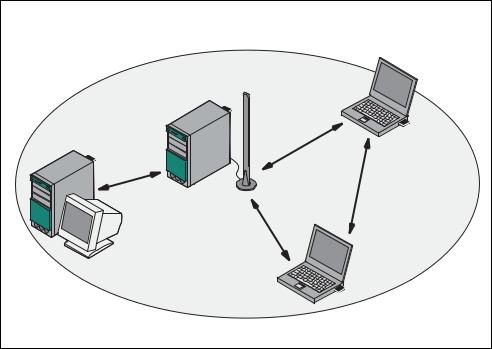
Ad Hoc Networks
In the ad hoc mode, nodes communicate directly with the server (connections 1 through 3 in the graphic below) without involving a SCALANCE W 788 or with each other (connection 4). The nodes access common resources (files or even devices, for example a printer) of the server. This is, of course, only possible when the nodes are within the wireless range of the server or within each other's range.
2
1
4
3
Figure 1-1 Ad Hoc Network without SCALANCE W 788
Operating Instructions SCALANCE W 788-1pro / SCALANCE W 788-2pro |
12 |
C79000-G8976-C184-01 |

Basic Information on Wireless LAN Communication
Standalone Configuration with the SCALANCE W 788
This configuration does not require a server and the SCALANCE W 788 does not have a connection to a wired Ethernet. Within its transmission range, the SCALANCE W 788 forwards data from one WLAN node to another.
The wireless network has a unique name. All the devices exchanging data within this network must be configured with this name.
Figure 1-2 Standalone Configuration of a SCALANCE W 788. The gray area indicates the wireless transmission range of the SCALANCE W 788.
Operating Instructions SCALANCE W 788-1pro / SCALANCE W 788-2pro |
13 |
C79000-G8976-C184-01 |
Basic Information on Wireless LAN Communication
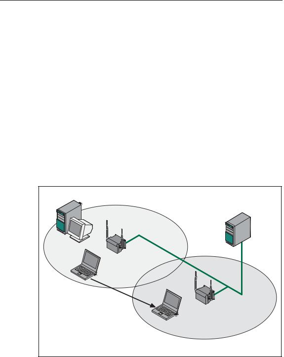
Wireless Access to a Wired Ethernet Network
If one (or more) SCALANCE W 788 access points have access to wired Ethernet, the following applications are possible:
●A single SCALANCE W 788 as gateway:
A computer equipped only with an Ethernet adapter can be integrated in the client mode in a wireless network over the SCALANCE W 788-1pro.
●Span of wireless coverage for the wireless network with several SCALANCE W 788 access points:
The SCALANCE W 788 access points are all configured with the same unique SSID (network name). All nodes that want to communicate over this network must also be configured with this SSID.
If a mobile station moves from the coverage range (cell) of one
SCALANCE W 788 to the coverage range (cell) of another SCALANCE W 788, the wireless connection is maintained (this is called roaming).
Figure 1-3 Connecting Two SCALANCE W 788 Access Points to a Wired Ethernet
14 |
Operating Instructions SCALANCE W 788-1pro / SCALANCE W 788-2pro |
C79000-G8976-C184-01 |

Basic Information on Wireless LAN Communication
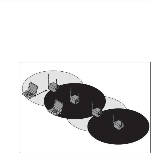
Multichannel Configuration
If neighboring SCALANCE W 788 access points use the same frequency channel, the response times are longer due to the collisions that occur. If the configuration shown in Figure 1-4 is implemented as a single-channel system, computers A and B cannot communicate at the same time with the SCALANCE W 788-1pro access points in their cells.
If neighboring SCALANCE W 788 access points are set up for different frequencies, this leads to a considerable improvement in performance. As a result, neighboring cells each have their own medium and the delays resulting from time-offset transmission no longer occur.
Channel spacing should be as large as possible; a practical value would be 25 MHz (five channels). Even in a multichannel configuration, all SCALANCE W 788 access points can be configured with the same network name.
|
1 |
A |
7 |
|
|
|
1 |
|
B |
|
7 |
Figure 1-4 Multichannel Configuration on Channels 1 and 7 with four
SCALANCE W 788 Access Points
Operating Instructions SCALANCE W 788-1pro / SCALANCE W 788-2pro |
15 |
C79000-G8976-C184-01 |
Basic Information on Wireless LAN Communication
Wireless Distribution System (WDS)
WDS allows direct connections between SCALANCE W 788 access points. These are used to create a wireless backbone or to connect an individual
SCALANCE W 788 to a network that cannot be connected directly to the cable infrastructure due to its location.
Two alternative configurations are possible. The WDS partner can be configured both using its name and its MAC address.
1 |
A
B
7 |
1 |
7 |
Figure 1-5 Implementation of WDS with four SCALANCE W 788 Access Points
16 |
Operating Instructions SCALANCE W 788-1pro / SCALANCE W 788-2pro |
C79000-G8976-C184-01 |

Basic Information on Wireless LAN Communication
Operating Instructions SCALANCE W 788-1pro / SCALANCE W 788-2pro |
17 |
C79000-G8976-C184-01 |
Description of the SCALANCE W 700 |
2 |
|
Components of the Product
The following components are supplied with the SCALANCE W 700:
●SCALANCE W 744-1pro, SCALANCE W 788-1pro or SCALANCE W 788-2pro
●2 OMNI antennas
●1 Harting RJ-45 hybrid cable connector
●1 dummy plug for the M12 socket
●2 (or 4 for the SCALANCE W 788-2pro) dummy plugs for the R-SMA sockets
●1 SIMATIC NET Industrial Wireless LAN CD
●These Operating Instructions for the SCALANCE W 700
Please check that the consignment you have received is complete. If it is not complete, please contact your supplier or your local Siemens office.
Requirements for Installation and Operation
There must be a network attachment available for the SCALANCE W 788 since the device is configured over the Ethernet interface. If no DHCP server is available, a PC on which the Primary Setup Tool is installed and can be used is necessary for the initial assignment of an IP address to the SCALANCE W 788. For the other configuration settings, a computer with Telnet or an Internet browser is necessary.
Operating Instructions SCALANCE W 788-1pro / SCALANCE W 788-2pro |
18 |
C79000-G8976-C184-01 |

Description of the SCALANCE W 700
Possible Applications of the SCALANCE W 788
The SCALANCE W 788 is equipped with an Ethernet interface and a wireless LAN interface (SCALANCE W 788-2pro: two WLAN interfaces). This makes the device suitable for the following applications:
●The SCALANCE W 788 forwards data within its transmission range from one node to another without a connection to wired Ethernet.
●The SCALANCE W 788 is used as a gateway from a wired to a wireless network.
●The SCALANCE W 788 can be used as a bridge between two networks.
Due to its second WLAN interface, the SCALANCE W 788-2pro can also be used to implement a redundant wireless connection between two SCALANCE W 7882pro devices.
Properties of the SCALANCE W 788
●The Internet interface supports 10 Mbps and 100 Mbps, full duplex and half duplex in both cases.
●The wireless interface is compatible with the standards IEEE 802.11a,
IEEE 802.11b and IEEE 802.11g. In the 802.1aand 802.1g modes, the transmission rate is up to 54 Mbps.
●Operation in the 2.4 GHz and 5 GHz frequency bands.
●Support of the authentication standards WPA, WPA-PSK and IEEE 802.1x and WEP, AES and TKIP encryption schemes.
●Suitable for inclusion of a RADIUS server for authentication.
●Device-related and application-related monitoring of the wireless connection.
Ports
The SCALANCE W 788 has the following ports:
●A Harting RJ-45 hybrid socket on the front panel of the housing for connection of an Ethernet cable and for the power supply (hybrid connector for power over Ethernet).
●An M12 socket for the power supply.
●Two R-SMA sockets (four R-SMA sockets on the SCALANCE W 788-2pro) for the attachment of antennas on the sides of the device.
Note
In the version for USA/Canada, two fixed antennas are fitted. On the SCALANCE W 788-2pro, the antennas of the second wireless card can be detached. The second wireless card can only be operated at 2.4 GHz
Operating Instructions SCALANCE W 788-1pro / SCALANCE W 788-2pro |
19 |
C79000-G8976-C184-01 |

Description of the SCALANCE W 700
LED Display
On the front of the housing, several LEDs provide information on the operating status of the SCALANCE W 788:
SCALANCEW788-1pro |
|
|
|
||
P1 |
L2 |
R1 |
|
L1 |
F |
SCALANCEW788-2pro |
|
|
|
||
P1 |
L2 |
R1 |
R2 |
L1 |
F |
Figure 2-1 The LEDs of the SCALANCE W 788
The LEDs have the following significance:
LED |
Color |
Meaning |
P1 |
Yellow |
Data transfer over the Ethernet interface. |
|
Green |
There is a connection over the Ethernet interface. |
|
|
|
L2 |
Green |
Power supply over hybrid connector. |
|
|
|
R1 |
Yellow |
Data transfer over the first WLAN interface. |
|
Green |
There is a connection over the first WLAN interface. |
|
|
|
R2 |
Yellow |
Data transfer over the second WLAN interface. |
|
|
|
|
Green |
There is a connection over the second WLAN interface. |
20 |
Operating Instructions SCALANCE W 788-1pro / SCALANCE W 788-2pro |
C79000-G8976-C184-01 |
Description of the SCALANCE W 700
L1 |
Green |
Power supply over the M12 connector. |
F |
Red |
An error occurred during operation with the SCALANCE W 788. |
|
|
|
Configuration Information on the C Plug
The C Plug is used to transfer the configuration of the old device to the new device when a device is replaced. When the new device starts up, it continues with exactly the same configuration as the old device. The only exception to this can be the IP configuration if it is set over DHCP and the DHCP server has not been reconfigured accordingly.
Replacing the C Plug
Follow the steps below to replace a C Plug in a SCALANCE W 788:
1.Remove the old SCALANCE W 788 from its mounting and open the sealing screw on the rear with a coin or broad screwdriver.
2.Remove the C Plug.
3.Open the sealing screw of the new device in the same way and insert the C Plug of the old device.
4.Replace the sealing screws of both devices.
If a new C Plug is inserted in a SCALANCE W 788-1pro, the configuration stored locally on the SCALANCE W 788-1pro is saved to the C Plug. If an incorrect C Plug (for example from another device or a damaged plug) is inserted, the SCALANCE W 788 signals an error with the red LED. The user then has the choice of either removing the C Plug again or selecting the option to reformat the C Plug and use it.
Operating Instructions SCALANCE W 788-1pro / SCALANCE W 788-2pro |
21 |
C79000-G8976-C184-01 |

Commissioning |
3 |
|
Lightning Protection
!Warning
Antennas installed outdoors must be within the area covered by a lightning protection system. Make sure that all conducting systems entering from outdoors can be protected by a lightning protection potential equalization system.
When implementing your lightning protection concept, make sure you adhere to the VDE 0182 or IEC 62305 standard.
Securing the Housing
There are three ways of securing the housing:
●Use the holes in the housing to screw the device to the wall or on a horizontal surface.
●There are clips on the rear of the device for securing it to a DIN rail.
●Fit the SCALANCE W 788 into a mounting channel
Operating Instructions SCALANCE W 788-1pro / SCALANCE W 788-2pro |
22 |
C79000-G8976-C184-01 |

Commissioning
Connectors for the Power Supply and for Ethernet
The SCALANCE W 788 is attached to Ethernet via a hybrid socket on the front of the housing (position A in Figure 3.1). This port also has contacts for the operating voltage.
Note
If you do not use the hybrid socket, this must be covered with a protective cap, otherwise IP65 protection is lost. A suitable protective cap is available as an accessory.
As an alternative or in addition to this, you can also use the M12 socket for the power supply (position B in Figure 3.1).
You can fit additional antennas to the sides of the SCALANCE W 788-2pro (position C in Figure 3.1).
Note
The distance between a pair of antennas for the first and second WLAN interface should be at least 0.5 m.
Note
In the version for USA/Canada, two fixed antennas are fitted. On the SCALANCE W 788-2pro, the antennas of the second wireless card can be detached. The second wireless card can only be operated at 2.4 GHz
A
B 


 C
C
Figure 3-1 Connectors of the SCALANCE W 788
Operating Instructions SCALANCE W 788-1pro / SCALANCE W 788-2pro |
23 |
C79000-G8976-C184-01 |

Commissioning
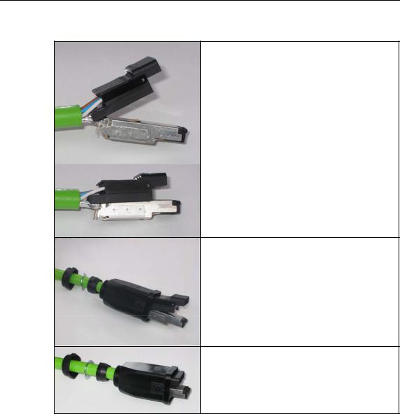
Assembling the Hybrid Connector
Remove the two inner shells of the universal sealing ring to adapt it to the diameter of the hybrid cable.
Push the bushing, washer, adapted universal sealing ring and the housing over the cable jacket.
Strip the cable jacket and braid shield to the correct lengths.
25 mm for the power leads.
30 mm (jacket) for the data leads (shorten the braid by 11 mm).
Arrange the data leads according to the color code on the splice element.
Refer to the table below for the assignment.
Contact and color assignment of the splice element.
24 |
Operating Instructions SCALANCE W 788-1pro / SCALANCE W 788-2pro |
C79000-G8976-C184-01 |

Wire color code (stan- |
White / |
Orange |
White / |
Green |
|
dard) |
orange * |
Green * |
|||
|
|
||||
Connector color code |
White |
Blue |
Yellow |
Orange |
|
(Siemens IE) |
|||||
|
|
|
|
||
Siemens IE FC RJ-45 |
3 |
6 |
1 |
2 |
|
jack (reference) |
|||||
|
|
|
|
* White wire of the colored pair.
Insert all the data leads at the same time up to the end of the splice element.
Fit the splice element onto the RJ-45-data module and click in place.
Insert the data module and splice element into the supplied IDC assembly tool.
Press the data module and IDC assembly tool together so that the insulation piercing connection is established.
Operating Instructions SCALANCE W 788-1pro / SCALANCE W 788-2pro |
25 |
C79000-G8976-C184-01 |

Commissioning
Remove the assembled data module from the IDC assembly tool.
Fit the upper shield plate and press it over the cable shield.
Then fit the lower shield plate and snap it into the upper plate (there should be an audible click).
Arrange the power leads and insert them to the end of the hinged elements of the insulator body.
Refer to the table below for the assignment.
Wire color code (standard) |
White / |
Blue |
White / |
Brown |
|
Blue * |
Brown * |
||||
|
|
|
|||
|
24 V |
24 V |
Ground |
Ground |
|
|
|
|
|
|
|
Power supply |
1 |
2 |
3 |
4 |
|
insert |
|||||
|
|
|
|
26 |
Operating Instructions SCALANCE W 788-1pro / SCALANCE W 788-2pro |
C79000-G8976-C184-01 |
Commissioning
Press the hinged elements and the integrated IDC contact together individually.
Recommendation: Use a small slotted screwdriver (max. 3.5 mm) as a lever.
Push the housing over assembled data module and the insulator body until they lock together (there should be an audible click).
Tighten the bushing. We recommend an open ring key with a size of 21 mm.
Operating Instructions SCALANCE W 788-1pro / SCALANCE W 788-2pro |
27 |
C79000-G8976-C184-01 |
Configuration with the Primary Setup Tool |
4 |
4.1Introduction
Initial Assignment of an IP Address
An initial IP address for the SCALANCE W 788 cannot be assigned using Web Based Management or the Command Line Interface because these configuration tools require that an IP address already exists.
The initial IP address can be obtained over DHCP or assigned using the Primary Setup Tool. The Primary Setup Tool is capable of assigning such an address to unconfigured devices without an IP address. The only condition is that the devices can be reached over Ethernet.
Operating Systems Supported
The Primary Setup Tool can be installed and used with the following operating systems:
●Windows XP Professional
●Windows 2000 Professional SP2
DLC Protocol
The Primary Setup Tool uses the DLC protocol for communication with the modules. This protocol is not supplied with Windows XP and must be installed extra for this operating system.
Follow the steps below to check whether or not the DLC protocol exists on your computer:
1.Select the menu command Start > Settings > Control Panel >Network and Dial-Up Connections.
2.Select the connection to your Ethernet communication module.
Operating Instructions SCALANCE W 788-1pro / SCALANCE W 788-2pro |
28 |
C79000-G8976-C184-01 |

Configuration with the Primary Setup Tool
3.Right-click to open the context menu and select Properties. The General tab lists all clients, protocols and services. The DLC protocol should also be listed and selected:
If the DLC protocol is listed, you can skip to the next but one section "Installing the Primary Setup Tool". If there is no entry for the DLC protocol, install it as described in the next section.
Operating Instructions SCALANCE W 788-1pro / SCALANCE W 788-2pro |
29 |
C79000-G8976-C184-01 |

Configuration with the Primary Setup Tool
4.2Installing the DLC Protocol
Extracting the Archive File
The files for installing the DLC protocol are in the self-extracting ZIP archive pst_xp_install.exe. Follow the steps below to extract the files from the archive:
1.Double-click on the file name pst_xp_install.exe in the Windows Explorer or start the program using the Windows menu command Start > Run.
2.In the dialog box of the extraction program, select the folder into which you want to extract the files and click on the Unzip button.
Installation
Follow the steps below to install the DLC protocol on your computer:
1.Select the menu command Start > Settings > Control Panel >Network and Dial-Up Connections.
2.Select the connection to your Ethernet communication module.
3.Right-click to open the context menu and select Properties.
4.Click on the Install... button in the General tab.
5.In the Select Network Component Type dialog, select the entry Protocol and click the Add... button.
6.In the Network Protocol dialog, click the Have Disk... button.
7.In the Install from Disk dialog, click the Browse... button.
8.In the file list box, change to the folder with the extracted installation files, select the netdlc.inf file and click the Open button.
9.In the Install from Disk dialog, click OK. The protocol is installed; the list box in the properties dialog of the communication module now includes the entry
DLC Protocol (Windows 2000/XP) for Siemens Primary Setup Tool.
10.Close the properties dialog by clicking the OK button.
30 |
Operating Instructions SCALANCE W 788-1pro / SCALANCE W 788-2pro |
C79000-G8976-C184-01 |
 Loading...