


WL Trip Unit, MODBUS Communication
and Electronic Accessories Application
Guide
powerful ideas
RELIABLE SOLUTIONS
WL Low Voltage Power
Circuit Breaker
 ANSI / UL1066 & UL 489
Global network of innovation
Communication-capable Circuit Breakers
WL Circuit Breaker
Technological Leader Among Circuit Breakers: WL Communication
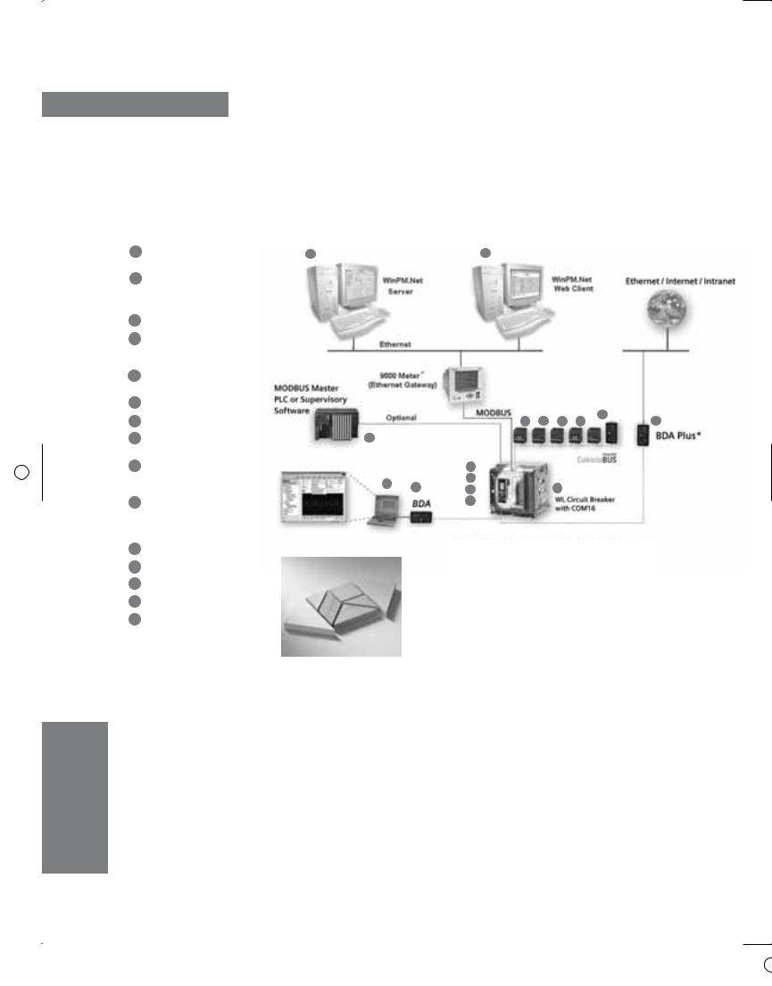
Connection Diagram |
|
|
1 Breaker Data Adapter |
13 |
13 |
(BDA) |
|
|
2Browser-capable input and output device (e.g. notebook)
3 WL Circuit Breaker
4COM16 MODBUS module or COM 15 PROFIBUS module
5Breaker Status Sensor (BSS)
6 |
Electronic Trip Unit |
|
|
|
|
|
7 |
Metering function PLUS |
15 |
||||
8 |
Zone Selective |
14 |
|
|
|
|
|
Interlocking (ZSI) module |
|
|
|
|
|
9 |
Digital output module |
4 |
|
|
|
|
|
|
|
|
|||
|
with relay or optocoupler |
5 |
|
|
|
|
|
|
|
|
|
||
|
outputs |
2 |
|
|
|
|
|
|
6 |
|
|
|
|
|
|
|
|
|
|
|
10 |
Digital output module |
7 |
|
|
|
|
|
|
|
||||
|
with relay or optocoupler |
|
|
|
|
|
|
outputs, remotely |
|
|
|
|
|
|
configurable |
|
|
|
|
|
11Analog output module
12Digital input module
13WinPM.Net on PC
14PLC (e.g. SIMATIC S7)
15BDA Plus
* The Siemens BDA Plus or meters, 9330, 9350, 95/9600 can be used as a gateway to enable Ethernet communication to the WL Circuit Breaker.
The 9500 meter can also be used as a central display unit for multiple WL breakers with metering capability.

Communication-capable
Circuit Breaker
Introduction and Overview
WL Circuit Breaker
MODBUS Profile for WL Circuit Breaker
Breaker Data Adapter (BDA)
Breaker Data Adapter Plus (BDA Plus)
1
2
3
4
WL MODBUS Communication and Electronic Accessories • January 2005

Communication-capable Circuit Breakers
WL Circuit Breaker
Safety Guidelines
This manual contains notices which you should observe to ensure your own personal safety, as well as to protect the product and connected equipment. These notices are highlighted in the manual by a warning triangle and are marked as follows according to the level of danger. This equipment contains hazardous voltages. Death, serious personal injury or property damage can result if safety instructions are not followed.
Only qualified personnel should work on or around this equipment after becoming thoroughly familiar with all warnings, safety notices, and maintenance procedures contained herein. The successful
and safe operation of this equipment is dependent upon proper handling, installation, operation and maintenance.
Danger
For the purpose of this manual and product labels, DANGER indicates an imminently hazardous situation which, if not avoided, will result in death or serious injury.
Warning
For the purpose of this manual and product labels, WARNING indicates a potentially hazardous situation which, if not avoided, could result in death or serious injury.
Caution
For the purpose of this manual and product labels, CAUTION indicates a potentially hazardous situation which, if not avoided, may result in minor or moderate injury.
Attention
Draws your attention to particularly important information on the product, handling the product or to a particular part of the documentation.
Qualified Personnel
For the purpose of this manual and product labels, a qualified person is one who is familiar with the installation, construction and operation of the equipment, and the hazards involved. In addition, he or she has the following qualifications:
(a)Is trained and authorized to energize, de-energize, clear, ground and tag circuits and equipment in accordance with established safety practices.
(b)Is trained in the proper care and use of protective equipment, such as rubber gloves, hard hat, safety glasses or face shield, flash clothing, etc., in accordance with established safety practices.
(c)Is trained in rendering first aid.
Correct Usage
Note the following:
Warning
This device and its components may only be used for the applications described in the catalog or the technical descriptions, and only in connection with devices or components from other manufacturers which have been approved or recommended by Siemens.
This product can only function correctly and safely if it is transported, stored, set up, and installed correctly, and operated and maintained as recommended.
Registered Trademarks
WinPM.Net is a registered trademark of Siemens Energy & Automation. MODBUS® is a registered trademark of MODICON. Some other designations used in these documents are also brands;
the owner's rights may be violated if they are used by third parties for their own purposes. Excel and Explorer are registered trademarks of Microsoft Corporation. Java is a registered trademark of Sun Microsystems. Netscape is a registered trademark of AOL Time Warner.
WL MODBUS Communication and Electronic Accessories • January 2005

Introduction and
Overview
1
Content of the Manual
Overview of the Bus Systems
Communicating with the Circuit Breaker
WL MODBUS Communication and Electronic Accessories • January 2005

Introduction and Overview
WL Circuit Breaker
General
This manual is aimed at those who want to find out more about the different applications of communications-capable circuit breakers in power distribution systems.
It contains a detailed guide to commissioning, operating, diagnosing and maintaining the new communications-capable WL Circuit Breaker.
Content of the Manual
Chapter 1 contains a short introduction to communications in power distribution systems, and provides an overview of the benefits and applications of communicationscapable circuit breakers. The chapter concludes with a short description of the most important communication bus systems.
Chapter 2 contains a general description of the WL Circuit Breaker. It includes information on configuration data and provides commissioning instructions.
Chapter 3 explains how the circuit breakers are integrated in a power management system and describes the supported function codes, register maps and exception codes.
WL is the first circuit breaker that can be configured, diagnosed and maintained remotely without the use of field bus systems and higher-level operator control and monitoring
systems. These procedures are carried out using the breaker data adapter (BDA), a state-of-the-art Internetcapable configuration device for circuit breakers, which is described in Chapter 4.
Introduction
The demand for communicationscapable systems, data transparency and flexibility in industrial automation systems is growing all the time. Bus systems and intelligent switchgear are vital to ensure that industrial power systems can meet these demands, since industrial production and building management are now inconceivable without communications technology.
The evermore-stringent requirements placed on the electrical and mechanical aspects of circuit breakers, the growing need for flexibility and efficiency, and increasing cost pressure and automation have contributed to the recent major innovations in circuit breaker technology. In power distribution systems, the WL Circuit Breaker uses industry-standard bus systems to transmit key information for warnings, commissioning and load shedding to a central control room. The wide range of applications ensure that these circuit breakers are more than just simple switching and protective devices.
Point-to-point communication, as well as data entry, transmission, analysis and visualization are only possible if the automation and lowvoltage switchgear technology components can be easily integrated in a communication solution to leverage the full range of functions available.
1/1
WL MODBUS Communication and Electronic Accessories • January 2005

In this way, status information, alarms, trip information and setpoints (e.g. overcurrent, phase unbalance, overvoltage) increase transparency in power distribution systems, enabling these situations to be dealt with quickly. A communication host can send short text messages to the cell phones of maintenance personnel. Prompt analysis of this data enables targeted intervention in the process and helps reduce system down time.
Information for preventive maintenance (e.g. the number of operating cycles or hours) enables timely personnel and material scheduling, which increases system availability and helps prevent sensitive system components from being damaged.
Communication helps provide rapid and targeted information on the location and cause of power failures. The cause of the fault can be determined by recording the phase currents (e.g. trip as a result of a short-circuit of 2317 A in phase L2 on 08/27/2002 at 14:27). This information can be used to quickly rectify the fault and reduces downtime for quicker recovery.
Measuring and communicating power, power factor and energy allows an even greater number of applications. The availibility of power consumption data on a targeted basis for business analysis enables power profiles to be created and costs to be clearly assigned. In this way, energy costs can be allocated and optimized by balancing the peak loads.
Introduction and Overview
WL Circuit Breakers—Modular and
Intelligent
Thousands of options with just a few components: That's the WL. A new generation of circuit breakers – from 200A to 5000A – with a modular design to support every conceivable application in power distribution systems – cost effective and flexible, its communication functionality enables it to be integrated in
system solutions.
Cost Saving
Whatever the configuration, the WL Circuit Breaker does the job where it matters. Advantages include simple retrofitting and a compact design benefiting everyone who uses WL Circuit Breakers, whether in planning, business, or whether they develop or operate switchgear systems.
Easy Planning
WL Circuit Breaker
Graphic Saving costs increases 1-1 productivity.
The WL Circuit Breaker and EasyTCC together provide a convenient software package for coordinating multiple circuit breakers.
Graphic Simplified planning every
1-2 |
step of the way. |
|
System Solutions
By integrating WL Circuit Breakers in a higher-level communication system, they can be configured via MODBUS, Ethernet or the Internet; an integrated power management system allows you to optimize power distribution across the board.
System solutions - Supports Graphic energy management through
1-3 advanced metering and communications.
1/2
WL MODBUS Communication and Electronic Accessories • January 2005

Introduction and Overview
WL Circuit Breaker
Communication Bus Systems
Communication bus systems are used to connect distribution devices with varying levels of intelligence. With their different structures and mechanisms, certain bus systems are designed for highly specific applications, while others are better suited for more open applications. The following section describes the most important bus systems used in automation and power distribution systems.
MODBUS
MODBUS is an open, serial communications protocol based on a master-slave architecture. Since it is very easy to implement on any kind of serial interface, it can be used in a wide range of applications. MODBUS comprises a master and several slaves, whereby communication is controlled exclusively by the master. MODBUS features two basic communication mechanisms:
•Question/answer (polling): The master sends an inquiry to a station and waits for a response.
•Broadcast: The master sends a command to all the network stations, which execute the command without confirmation.
The messages enable process data (input/output data) to be written to and read from the slaves either individually or in groups.
The data can either be transmitted in ASCII or as a package in RTU format. MODBUS can be used over a wide range of transmission media, normally, on an RS 485 physical bus, a twisted, shielded two-wire cable with terminating resistors.
The MODBUS protocol was originally developed for networking control systems, and is often used for connecting input/output modules to a central PLC. Due to the low transmission rate of 38.4 kBaud max., MODBUS is particularly recommended for applications with a low number of stations or low response time requirements.
1/3
WL MODBUS Communication and Electronic Accessories • January 2005
Introduction and Overview
WL Circuit Breaker
Communication Structure of the
WL Circuit Breakers
The following diagram:
•Provides an overview of the different communication options available with WL Circuit Breakers and their modules.
•Illustrates the high level of system flexibility, enabling new and innovative ideas to be implemented.
Starting at the lowest level with simple configuration of the circuit breakers, to the field level with
a PLC and WinPM.Net software tool, to a connection to the Intranet/Internet, the potential for saving on power costs by means of intelligent power management is achieveable.
The individual circuit breakers and their modules are described in the following chapters.
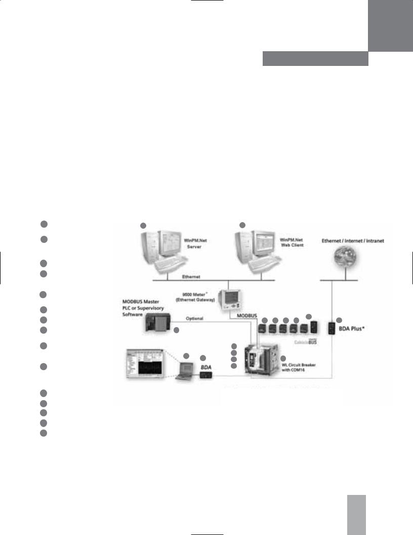
Connection Diagram |
|
|
1 Breaker Data Adapter |
13 |
13 |
(BDA) |
|
|
2Browser-capable input and output device (e.g. notebook)
3 WL Circuit Breaker
4COM16 MODBUS module or COM 15 PROFIBUS module
5Breaker Status Sensor (BSS)
6 |
Electronic Trip Unit |
|
|
|
|
|
7 |
Metering function PLUS |
15 |
||||
8 |
Zone Selective |
14 |
|
|
|
|
|
Interlocking (ZSI) module |
|
|
|
|
|
9 |
Digital output module |
4 |
|
|
|
|
|
|
|
|
|||
|
with relay or optocoupler |
5 |
|
|
|
|
|
|
|
|
|
||
|
outputs |
2 |
|
|
|
|
|
Digital output module |
6 |
|
|
|
|
|
|
|
|
|
||
10 |
7 |
|
|
|
|
|
|
|
|
||||
|
with relay or optocoupler |
|
|
|
|
|
|
outputs, remotely |
|
|
|
|
|
|
configurable |
|
|
|
|
|
11Analog output module
12Digital input module
13WinPM.Net on PC
14PLC (e.g. SIMATIC S7)
15BDA Plus
* The Siemens BDA Plus or meters, 9330, 9350, 95/9600 can be used as a gateway to enable Ethernet communication to the WL Circuit Breaker.
The 9500 meter can also be used as a central display unit for multiple WL breakers with metering capability.
1/4
WL MODBUS Communication and Electronic Accessories • January 2005

Introduction and Overview
WL Circuit Breaker
Ethernet
The Industrial Ethernet is a highperformance network that conforms to IEE 802.3 (ETHERNET). The highly successful 10Mbit/s technology, which has been used for over a decade, and the new 100Mbit/s technology (Fast Ethernet to IEEE 802.3u) in conjunction with Switching Full Duplex and Autosensing enable the required network performance to be adapted to different requirements. The appropriate data rates are selected as required because complete compatibility enables the technology to be implemented on
a step-by-step basis.
Used in 80% of networks, Ethernet is currently the best of its kind in LAN environments.
Ethernet does not function according to a master-slave principle. All the stations have equal priority on the bus, which means that any station can be the sender or receiver. A sender can only send on the bus if no other station is sending at that time. This is due to the fact that the stations are always "listening in" to find out whether any messages are being sent to them or any senders are currently active. If a sender has started sending, it checks that the message it has sent is not corrupt. If the message is not changed, the send operation continues.
If the sender detects that its data is corrupt, another sender must have already started sending data. In this case, both senders abort their respective send operations.
After a random time has elapsed, the sender restarts the send operation. This is known as CSMA/CD and, as a "random" access procedure, does not guarantee a response within a certain time frame. This largely depends on the bus load, which means that realtime applications cannot yet be implemented with Ethernet.
1/5
WL MODBUS Communication and Electronic Accessories • January 2005
WL Circuit Breaker
Short description of WL Circuit Breaker |
2 |
The CubicleBUS |
|
Communication Function of the Trip Units |
The COM16 MODBUS Module
Metering and Metering Plus
Description of Important Functions/Parameters for Communication
External CubicleBUS Modules
External Power Consumption of a WL Circuit Breaker with CubicleBUS
WL MODBUS Communication and Electronic Accessories • January 2005
Communication-capable Circuit Breakers
WL Circuit Breaker
Introduction and Overview
The demands regarding communications capability, data transparency, flexibility and integration in power distribution systems are increasing all the time. The WL Circuit Breaker
is a modular circuit breaker that fulfills the requirements of the future today.
Brief Description of the
WL Circuit Breaker
Circuit breakers today are no longer simply devices for protecting plants, transformers, generators and motors. Many users now require a complete overview of the plant from a central control room and round-the-clock access to all available information. Modern power distribution systems are characterized by the methods used to network circuit breakers— both with each other and other components. The circuit breakers in the
WL Circuit Breaker family have a lot to offer:
It is possible to carry out analysis and maintenance procedures remotely via the Internet. Operating staff can be given immediate access to information on system status and alarms. This is not just a vision of the future, but reality.
The WL Circuit Breaker covers the entire range from 200A to 5000A. The devices are available with different interrupting ratings, allowing shortcircuit currents of up to
200kA to be interrupted reliably.
WL Circuit Breakers can be adapted to different system conditions, which means that a rating plug can be used to adapt each circuit breaker to the appropriate rated current. This ensures that optimum protection is provided, even if changes have been made in the system. The modules (reference Graphic 2-1) can be replaced without the need for the transformer to be changed.
Note: Installation instructions related to the communication modules described in this section can be found in the individual instruction sheets and/or Section 9 of the Operator's Manual
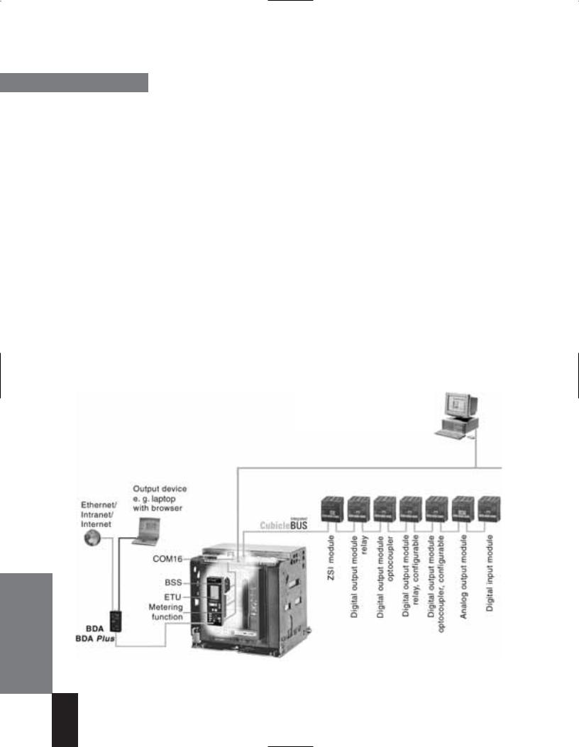
PC with WinPM.Net
WL Circuit Breaker configuration and monitoring software
Graphic 2-1 The system architecture of the WL Circuit Breaker with CubicleBUS enables simultaneous communication via MODBUS and BDA with a laptop or Ethernet/Intranet/Internet.
2/1
WL MODBUS Communication and Electronic Accessories • January 2005

The ability to change between two different parameter sets is also possible. This function is particularly useful in the event of a power failure when an automatic transfer is made from utility to generator power, a process which can
involve changing many of the trip unit parameters.
A wide range of lock-out systems are available to improve reliability during critical processes. All accessories, such as shunt trips, motor operators and communication components, can be installed quickly and easily; this is made easier because the accessories are identical across the entire product line. The commitment to reducing the overall number of parts results in fewer spares to be ordered and lower inventory costs.
The heart of each circuit breaker is the electronic trip unit (ETU). Several versions are available to adapt the protective, metering, and alarm functions to the system requirements: from simple overload and short-circuit protection to trip units that can be configured remotely and which feature a wide range of metering and alarm functions.
All circuit breakers with ETU745, ETU748, ETU755 and ETU776 trip units are communications capable, and allow additional components to be internally networked via the CubicleBUS.
The circuit breaker is connected to MODBUS via the RS485 interface on the COM16 module.
The breaker data adapter (BDA) (see Chapter 4) also supports higher-level networking/ communication (Intranet/Internet).
Communication-capable Circuit Breakers
WL Circuit Breaker
The CubicleBUS
The CubicleBUS, which connects all the intelligent components within the WL Circuit Breaker and enables additional external components to be connected quickly and reliably, forms the backbone of the modular architecture of the WL. The CubicleBUS is already integrated in and connected to all assembled circuit breakers with the ETU745, ETU748, ETU755, and ETU776
trip units.
The high level of system modularity enables communication functions (e.g. metering function) to be retrofitted at any time. A WL Circuit Breaker that is not communications capable can be upgraded (e.g. by exchanging ETU725 for ETU745 with CubicleBUS) quickly and easily on site. All CubicleBUS modules can access the existing data of the circuit breaker directly, thereby ensuring rapid access to information and speedy responses to events.
By connecting additional, external modules to the CubicleBUS, costeffective solutions for communicating data from other devices in the cubicle can be implemented.
Communications Capability of the
Electronic Trip Units (ETUs)
The electronic trip units ETU745, ETU748, ETU755, and ETU776 are all communications capable. The CubicleBUS is connected to the circuit breaker terminals X8.1(-) to X8.4(+)
Different versions of communications-capable trip units are available.
The front of the ETU745 has rotary switches for setting protective parameters. These can be read via the communication device. The ETU745 can also be installed with a four-line display for the measured values.
The ETU755 does not have rotary switches or a display. The protective parameters can only be changed via communications. This trip unit with remote-only parameter setting is for special application demands.
The ETU776 features a graphical display with a clearly structured, key-driven menu. This not only enables operators to display measured values, status information, and maintenance information, but also to read all the existing parameters and make password-protected changes.
2/2
WL MODBUS Communication and Electronic Accessories • January 2005
Communication-capable Circuit Breakers
WL Circuit Breaker
Functional overview of the trip unit system
Basic Functions |
|
|
ETU725 |
ETU727 |
ETU745 |
||||||||||||||||
|
|
|
|
|
|
|
|
|
|
|
|
|
|
|
|
|
|
Long-time overcurrent protection |
|
|
|
|
|
|
|
|
|
|
|
|
|
|
|
|
|
|
|
|
|
Function can be switched ON/OFF |
– |
– |
– |
|
|
|
|
|
|
|
|
|
|
|
|
|
|
|
|
|
|
Setting range IR = In x … |
0.4, 0.45, 0.5, 0.55, |
0.4, 0.45, 0.5, 0.55, |
0.4, 0.45, 0.5, 0.55, 0.6, |
|
|
|
|
|
|
|
|
|
|
|
|
|
|
|
|
|
|
|
0.6, 0.65, 0.7, 0.8, |
0.6, 0.65, 0.7, 0.8, |
0.65, 0.7, 0.8, 0.9, 1 |
|
|
|
|
|
|
|
|
|
|
|
|
|
|
|
|
|
|
|
0.9, 1 |
0.9, 1 |
|
In |
|
|
|
|
|
|
|
|
|
|
|
|
|
|
|
|
|
Switch-selectable overload protection |
|
|
|
|
|
|
|
|
|
|
|
|
|
|
|
|
|
|
|
L |
(I2t or I4t dependent function) |
– |
– |
|
|
|
|
|
|
|
|
|
|
|
|
|
|
|
|
|
|
|
|
||||
|
|
|
|
|
|
|
|
|
|
|
|
|
|
|
|
|
|
Setting range of time delay class tR at I2t |
10s, set at 6 x Ir |
10s, set at 6 x Ir |
2, 3.5, 5.5, 8, 10, |
|
|
|
|
|
|
|
|
|
|
|
|
|
|
|
|
|
|
(seconds) |
|||
|
|
|
|
|
|
|
|
|
|
|
|
|
|
|
|
|
|
||||
|
|
|
|
|
|
|
|
|
|
|
|
|
|
|
|
|
|
Setting range of time delay tR at I 4t |
|
|
14, 17, 21, 25, 30 |
|
|
|
|
|
|
|
|
|
|
|
|
|
|
|
|
|
|
|
|
|
|
|
|
|
|
|
|
|
|
|
|
|
|
|
|
|
|
|
|
(seconds) |
– |
– |
1, 2, 3, 4, 5 |
|
|
|
|
|
|
|
|
|
|
|
|
|
|
|
|
|
|
Thermal memory |
– |
– |
(via slide switch) |
|
|
|
|
|
|
|
|
|
|
|
|
|
|
|
|
|
|
Phase loss sensitivity |
at tsd=20 ms (M) |
at tsd=20 ms (M) |
at tsd=20 ms (M) |
|
|
|
|
|
|
|
|
|
|
|
|
|
|
|
|
|
|
||||
|
|
|
|
|
|
|
|
|
|
|
|
|
|
|
|
|
N |
Neutral protection |
– |
|
|
|
|
|
|
|
|
|
|
|
|
|
|
|
|
|
|
|
|||||
|
|
|
|
|
|
|
|
|
|
|
|
|
|
|
|
|
Function can be switched ON/OFF |
– |
(via slide switch) |
(via slide switch) |
|
|
|
|
|
|
|
|
|
|
|
|
|
|
|
|
|
|
|
N-conductor setting range IN = In x … |
– |
1 |
0.5 … 1 |
|
|
|
|
|
|
|
|
|
|
|
|
|
|
|
|
|
|
Short-time delayed overcurrent protection |
|
|
|
|
|
|
|
|
|
|
|
|
|
|
|
|
|
|
|
|
|
Function can be switched ON/OFF |
– |
– |
(via rotary switch) |
|
|
|
|
|
|
|
|
|
|
|
|
|
|
|
|
|
|
Setting range Isd = In x … |
1.25, 1.5, 2, 2.5, |
1.25, 1.5, 2, 2.5, |
1.25, 1.5, 2, 2.5, |
|
|
|
|
|
|
|
|
|
|
|
|
|
|
|
|
|
|
|
3, 4, 6, 8, 10, 12 |
3, 4, 6, 8, 10, 12 |
3, 4, 6, 8, 10, 12 |
|
|
|
|
|
|
|
|
|
|
|
|
|
|
|
|
|
S |
Setting range of time delay tsd, fixed |
|
|
|
|
|
|
|
|
|
|
|
|
|
|
|
|
|
|
|
|
(seconds) |
0, 0.02 (M), 0.1, |
0, 0.02 (M), 0.1, |
0.02 (M), 0.1, 0.2, |
|
|
|
|
|
|
|
|
|
|
|
|
|
|
|
|
|
|
|
|
0.2, 0.3, 0.4 |
0.2, 0.3, 0.4 |
0.3, 0.4, OFF |
|
|
|
|
|
|
|
|
|
|
|
|
|
|
|
|
|
|
Switch-selectable short-time delay |
|
|
|
|
|
|
|
|
|
|
|
|
|
|
|
|
|
|
|
|
|
short-circuit protection |
|
|
|
|
|
|
|
|
|
|
|
|
|
|
|
|
|
|
|
|
|
(I2t dependent function) |
– fixed only |
– fixed only |
(via rotary switch) |
|
|
|
|
|
|
|
|
|
|
|
|
|
|
|
|
|
|
Setting range of time delay tsd at I2t |
|
|
|
|
|
|
|
|
|
|
|
|
|
|
|
|
|
|
|
|
|
(seconds) |
– |
– |
0.1, 0.2, 0.3, 0.4 |
|
|
|
|
|
|
|
|
|
|
|
|
|
|
|
|
|
|
Zone Selective Interlocking (ZSI) function |
– |
– |
per CubicleBUS module |
|
|
|
|
|
|
|
|
|
|
|
|
|
|
|
|
|
|
||||
|
|
|
|
|
|
|
|
|
|
|
|
|
|
|
|
|
|
Instantaneous overcurrent protection |
|
|
|
|
|
|
|
|
|
|
|
|
|
|
|
|
|
|
|
|
|
Function can be switched ON/OFF, |
|
|
|
|
|
|
|
|
|
|
|
|
|
|
|
|
|
|
|
|
|
|
|
|
|
|
|
|
|
|
|
|
|
|
|
|
|
|
|
|
|
|
I |
Extended Instantaneous Protection |
|
|
|
|
|
|
|
|
|
|
|
|
|
|
|
|
|
|
|
|
is enabled when OFF |
– |
– |
(via rotary switch) |
|
|
|
|
|
|
|
|
|
|
|
|
|
|
|
|
|
|
|
Setting range Ii = In x … |
Ii = 0.8 x Icw |
Ii = 0.8 x Icw |
1.5, 2.2, 3, 4, 6, 8, 10, 12 |
|
|
|
|
|
|
|
|
|
|
|
|
|
|
|
|
|
|
|
50kA max |
50kA max |
0.8 x Icw = max, OFF=I cw=EIP 1 |
|
|
|
|
|
|
|
|
|
|
|
|
|
|
|
|
|
|
Ground fault protection 2 |
– |
(standard) |
O (field installable module) |
|
|
|
|
|
|
|
|
|
|
|
|
|
|
|
|
|
|
||||
|
|
|
|
|
|
|
|
|
|
|
|
|
|
|
|
|
|
Trip and alarm function |
– |
– |
|
|
|
|
|
|
|
|
|
|
|
|
|
|
|
|
|
|
|
Detection of the ground fault current |
|
|
|
|
|
|
|
|
|
|
|
|
|
|
|
|
|
|
|
|
|
by residual summing method |
– |
|
|
|
|
|
|
|
|
|
|
|
|
|
|
|
|
|
|
|
|
Detection of the ground fault current |
|
|
|
|
|
|
|
|
|
|
|
|
|
|
|
|
|
|
|
|
|
by direct sensing method |
– |
– |
|
|
|
|
|
|
|
|
|
|
|
|
|
|
|
|
|
|
G |
Setting range of the Ig for trip |
– |
A, B, C, D, E |
A, B, C, D, E |
|
|
|
|
|
|
|
|
|
|
|
|
|
|
|
|
|
|
Setting range of the Ig for alarm |
– |
– |
A, B, C, D, E |
|
|
|
|
|
|
|
|
|
|
|
|
|
|
|
|
|
|
Setting range of the time delay tg |
|
|
|
|
|
|
|
|
|
|
|
|
|
|
|
|
|
|
|
|
|
|
|
|
|
|
|
|
|
|
|
|
|
|
|
|
|
|
|
|
|
|
|
(seconds) |
– |
0.1, 0.2, 0.3, 0.4, 0.5 |
0.1, 0.2, 0.3, 0.4, 0.5 |
|
|
|
|
|
|
|
|
|
|
|
|
|
|
|
|
|
|
||||
|
|
|
|
|
|
|
|
|
|
|
|
|
|
|
|
|
|
Switch-selectable |
|
|
|
|
|
|
|
|
|
|
|
|
|
|
|
|
|
|
|
|
|
ground fault protection |
|
|
|
|
|
|
|
|
|
|
|
|
|
|
|
|
|
|
|
|
|
|
|
|
|
|
|
|
|
|
|
|
|
|
|
|
|
|
|
|
|
|
|
(I2t / fixed) |
– |
– |
|
|
|
|
|
|
|
|
|
|
|
|
|
|
|
|
|
|
|
Setting range time delay tg at I2t |
– |
– |
0.1, 0.2, 0.3, 0.4, 0.5 |
|
|
|
|
|
|
|
|
|
|
|
|
|
|
|
|
|
|
ZSI ground function |
– |
– |
per CubicleBUS module |
|
|
|
|
|
|
|
|
|
|
|
|
|
|
|
|
|
|
|
|
|
|
1Extended Instantaneous Protection (EIP) allows the WL breaker to be applied at the withstand rating of the breaker with minus 0% tolerance; that means no instantaneous override whatsoever. EIP further enables the circuit breaker to be applied up to the full instantaneous rating of the breaker on systems where the available fault current exceeds the withstand rating.
2 Ground Fault Module cannot be removed after installation.
available
– not available
Ooptional
2/3
WL MODBUS Communication and Electronic Accessories • January 2005

Communication-capable Circuit Breakers
WL Circuit Breaker
|
|
Basic Functions |
|
|
|
|
|
ETU725 |
|
ETU727 |
ETU745 |
|||||||||||||
|
|
Parameter sets |
|
|
|
|
|
|
|
|
|
|
|
|
||||||||||
|
|
|
|
|
|
|
|
|
|
|
|
|
|
|
Selectable between |
|
|
|
|
|
|
|
||
|
|
|
|
|
|
|
|
|
|
|
|
|
|
|
parameter set A and B |
|
|
– |
|
– |
– |
|||
|
|
LCD |
|
|
|
|
|
|
|
|
|
|
|
|
||||||||||
|
|
|
|
|
|
|
|
|
|
|
|
|
|
|
LCD, alphanumeric (4-line) |
|
|
– |
|
– |
O |
|||
|
|
|
|
|
|
|
|
|
|
|
|
|
|
|
LCD, graphic |
|
|
– |
|
– |
– |
|||
|
|
Communication |
|
|
|
|
|
|
|
|
|
|
|
|
||||||||||
|
|
|
|
|
|
|
|
|
|
|
|
|
|
|
CubicleBUS integrated |
|
|
– |
|
– |
|
|||
|
|
|
|
|
|
|
|
|
|
|
|
|
|
|
Communication capability via |
|
|
|
|
|
||||
|
|
|
|
|
|
|
|
|
|
|
|
|
|
|
MODBUS or PROFIBUS |
|
|
– |
|
– |
|
|||
|
|
Metering function |
|
|
|
|
|
|
|
|
|
|
||||||||||||
|
|
|
|
|
|
|
|
|
|
|
|
|
|
|
Metering function capability with |
|
|
|
|
|
||||
|
|
|
|
|
|
|
|
|
|
|
|
|
|
|
Metering Function PLUS |
|
|
– |
|
– |
|
|||
|
|
Display by LED |
|
|
|
|
|
|
|
|
|
|
|
|
||||||||||
|
|
|
|
|
|
|
|
|
|
|
|
|
|
|
Trip unit active |
|
|
|
|
|
|
|||
|
|
|
|
|
|
|
|
|
|
|
|
|
|
|
Alarm |
|
|
|
|
|
|
|||
|
|
|
|
|
|
|
|
|
|
|
|
|
|
|
ETU error |
|
|
|
|
|
|
|||
|
|
|
|
|
|
|
|
|
|
|
|
|
|
|
L trip |
|
|
|
|
|
|
|||
|
|
|
|
|
|
|
|
|
|
|
|
|
|
|
S trip |
|
|
|
|
|
|
|||
|
|
|
|
|
|
|
|
|
|
|
|
|
|
|
I trip |
|
|
|
|
|
|
|||
|
|
|
|
|
|
|
|
|
|
|
|
|
|
|
N trip |
|
|
– |
|
|
|
|||
|
|
|
|
|
|
|
|
|
|
|
|
|
|
|
G trip |
|
|
– |
|
|
(only with ground fault module) |
|||
|
|
|
|
|
|
|
|
|
|
|
|
|
|
|
G alarm |
|
|
– |
|
– |
(only with ground fault module) |
|||
|
|
|
|
|
|
|
|
|
|
|
|
|
|
|
Tripped by extended protection or |
|
|
|
|
|
||||
|
|
|
|
|
|
|
|
|
|
|
|
|
|
|
protective relay function |
|
|
– |
|
– |
|
|||
|
|
|
|
|
|
|
|
|
|
|
|
|
|
|
Communication |
|
|
– |
|
– |
|
|||
|
|
Signal contacts with external CubicleBUS modules |
|
|
|
|
|
|||||||||||||||||
|
|
(Opto or relay) |
|
|
|
|
|
|
|
|
|
|
|
|
||||||||||
|
|
|
|
|
|
|
|
|
|
|
|
|
|
|
Overcurrent warning |
|
|
– |
|
– |
|
|||
|
|
|
|
|
|
|
|
|
|
|
|
|
|
|
Load shedding ON/OFF |
|
|
– |
|
– |
|
|||
|
|
|
|
|
|
|
|
|
|
|
|
|
|
|
Early signal of long-time trip (200 ms) |
– |
|
– |
|
|||||
|
|
|
|
|
|
|
|
|
|
|
|
|
|
|
|
|||||||||
|
|
|
|
|
|
|
|
|
|
|
|
|
|
|
Temperature alarm |
|
|
– |
|
– |
|
|||
|
|
|
|
|
|
|
|
|
|
|
|
|
|
|
Phase unbalance |
|
|
– |
|
– |
|
|||
|
|
|
|
|
|
|
|
|
|
|
|
|
|
|
|
|
|
|||||||
|
|
|
|
|
|
|
|
|
|
|
|
|
|
|
Instantaneous trip |
|
|
– |
|
– |
|
|||
|
|
|
|
|
|
|
|
|
|
|
|
|
|
|
|
|
|
|||||||
|
|
|
|
|
|
|
|
|
|
|
|
|
|
|
Short-time trip |
|
|
– |
|
– |
|
|||
|
|
|
|
|
|
|
|
|
|
|
|
|
|
|
Long-time trip |
|
|
– |
|
– |
|
|||
|
|
|
|
|
|
|
|
|
|
|
|
|
|
|
|
|
|
|||||||
|
|
|
|
|
|
|
|
|
|
|
|
|
|
|
Neutral conductor trip |
|
|
– |
|
– |
|
|||
|
|
|
|
|
|
|
|
|
|
|
|
|
|
|
Ground fault protection trip |
|
|
– |
|
– |
(only with ground fault module) |
|||
|
|
|
|
|
|
|
|
|
|
|
|
|
|
|
|
|
|
|||||||
|
|
|
|
|
|
|
|
|
|
|
|
|
|
|
Ground fault alarm |
|
|
– |
|
– |
(only with ground fault module) |
|||
|
|
|
|
|
|
|
|
|
|
|
|
|
|
|
Auxiliary relay |
|
|
– |
|
– |
|
|||
|
|
|
|
|
|
|
|
|
|
|
|
|
|
|
ETU error |
|
|
– |
|
– |
|
|||
|
|
|
|
|
|
|
|
|
|
|
|
|
|
|
|
|
|
|
|
|||||
|
|
Step for Settings via Communications or ETU Key Pad |
Setting range of the Ig |
|
||||||||||||||||||||
|
|
|
|
|
|
|
|
|
|
|
|
|
|
|
|
|
|
|
|
|
|
|
|
|
|
|
from … to |
|
step |
from … to |
step |
|
|
Frame Size II |
Frame Size III |
|
|||||||||||||
|
|
|
|
|
|
|
|
|
|
|
|
|
|
|
|
|
|
|
|
|
|
|
|
|
|
|
0 … 1 |
|
0.1 |
1000 … 1600 |
50 |
|
A |
100 A |
400 A |
|
|||||||||||||
|
|
1 … 100 |
1 |
|
1600 … 10000 |
100 |
|
B |
300 A |
600 A |
|
|||||||||||||
|
|
100 … 500 |
5 |
|
10000 … max |
1000 |
|
C |
600 A |
800 A |
|
|||||||||||||
|
|
500 … 1000 |
10 |
|
|
|
|
|
D |
900 A |
1000 A |
|
||||||||||||
|
|
|
|
|
|
|
|
|
|
|
|
|
|
|
|
|
|
|
|
E |
1200 A |
1200 A |
|
|
|
available |
– |
not available |
O |
optional |
2/4
WL MODBUS Communication and Electronic Accessories • January 2005
Communication-capable Circuit Breakers
WL Circuit Breaker
Functional overview of the trip unit system
Basic Functions |
|
|
ETU748 |
ETU755 |
ETU776 |
|||||||||||||
|
|
|
|
|
|
|
|
|
|
|
|
|
|
|
Long-time overcurrent protection |
|
|
|
|
|
|
|
|
|
|
|
|
|
|
|
|
|
|
Function can be switched ON/OFF |
– |
– |
– |
|
|
|
|
|
|
|
|
|
|
|
|
|
|
|
Setting range IR = In x … |
0.4, 0.45, 0.5, 0.55, |
0.4 … 1 (step: 1A) |
0.4 … 1 (step: 1A) |
|
|
|
|
|
|
|
|
|
|
|
|
|
|
|
|
0.6, 0.65, 0.7, 0.8, |
|
|
|
|
|
|
|
|
|
|
|
|
|
|
|
|
|
|
0.9, 1 |
|
|
In |
|
|
|
|
|
|
|
|
|
|
|
|
|
|
Switch-selectable overload protection |
|
|
|
|
|
|
|
|
|
|
|
|
|
|
|
|
L |
(I2t or I4t dependent function) |
|
(via communications) |
|
|
|
|
|
|
|
|
|
|
|
|
|
|
|
|
|
Setting range of time delay class tR at I2t |
|
|
|
|
|
|
|
|
|
|
|
|
|
|
|
|
|
|
(seconds) |
2, 3.5, 5.5, 8, 10, |
2 … 30 (step: 0.1s) |
2 … 30 (step: 0.1s) |
|
|
|
|
|
|
|
|
|
|
|
|
|
|
|
||||
|
|
|
|
|
|
|
|
|
|
|
|
|
|
|
Setting range of time delay tR at I4t |
14, 17, 21, 25, 30 |
|
|
|
|
|
|
|
|
|
|
|
|
|
|
|
|
|
|
|
||
|
|
|
|
|
|
|
|
|
|
|
|
|
|
|
|
|
|
|
|
|
|
|
|
|
|
|
|
|
|
|
|
|
|
(seconds) |
1, 2, 3, 4, 5 |
1 … 5 (step: 0.1s) |
1 … 5 (step: 0.1s) |
|
|
|
|
|
|
|
|
|
|
|
|
|
|
|
Thermal memory |
(via slide switch) |
(on/off via communications) |
(on/off via key pad |
|
|
|
|
|
|
|
|
|
|
|
|
|
|
|
|
|
|
or communications) |
|
|
|
|
|
|
|
|
|
|
|
|
|
|
|
Phase loss sensitivity |
at tsd=20ms (M) |
(on/off via communications) |
(on/off via key pad |
|
|
|
|
|
|
|
|
|
|
|
|
|
|
|
|
|
|
or communications) |
|
|
|
|
|
|
|
|
|
|
|
|
|
|
|
Neutral protection |
– |
|
|
|
|
|
|
|
|
|
|
|
|
|
|
|
|
N |
Function can be switched ON/OFF |
– |
(via communications) |
(via key pad or communications) |
|
|
|
|
|
|
|
|
|
|
|
|
|
|
|
N-conductor setting range IN = In x … |
0.5, 1, OFF |
0.5, 1, OFF |
0.5 … 2, OFF |
|
|
|
|
|
|
|
|
|
|
|
|
|
|
|
Short-time delayed overcurrent protection |
|
|
|
|
|
|
|
|
|
|
|
|
|
|
|
|
|
|
Function can be switched ON/OFF |
– |
(via communications) |
(via key pad or communications) |
|
|
|
|
|
|
|
|
|
|
|
|
|
|
|
Setting range Isd = In x … |
1.25, 1.5, 2, 2.5, |
1.25 … 0.8 x Icw = max |
1.25 … 0.8 x Icw = max |
|
|
|
|
|
|
|
|
|
|
|
|
|
|
|
|
3, 4, 6, 8, 10, 12 |
(step: 10A) |
(step: 10A) |
|
|
|
|
|
|
|
|
|
|
|
|
|
|
S |
Setting range of time delay tsd, fixed |
|
|
|
|
|
|
|
|
|
|
|
|
|
|
|
|
|
(seconds) |
M, 0.1, 0.2, 0.3, 0.4 |
M, 0.08 …0.4, OFF (step: 0.001s) |
M, 0.08 …0.4, OFF (step: 0.001s) |
|
|
|
|
|
|
|
|
|
|
|
|
|
|
|
|
Switch-selectable short -time delay |
|
|
|
|
|
|
|
|
|
|
|
|
|
|
|
|
|
|
short-circuit protection |
|
|
|
|
|
|
|
|
|
|
|
|
|
|
|
|
|
|
(I2t dependent function) |
(via rotary switch) |
(via communications) |
(via key pad or communications) |
|
|
|
|
|
|
|
|
|
|
|
|
|
|
|
Setting range of time delay tsd at I2t |
|
|
|
|
|
|
|
|
|
|
|
|
|
|
|
|
|
|
(seconds) |
0.1, 0.2, 0.3, 0.4 |
0.1 … 0.4 (step: 0.001s) |
0.1 … 0.4 (step: 0.001s) |
|
|
|
|
|
|
|
|
|
|
|
|
|
|
|
Zone Selective Interlocking (ZSI) function |
per CubicleBUS module |
per CubicleBUS module |
per CubicleBUS module |
|
|
|
|
|
|
|
|
|
|
|
|
|
|
|
||||
|
|
|
|
|
|
|
|
|
|
|
|
|
|
|
Instantaneous overcurrent protection |
|
|
|
|
|
|
|
|
|
|
|
|
|
|
|
|
|
|
Function can be switched ON/OFF, |
|
|
|
|
|
|
|
|
|
|
|
|
|
|
|
|
|
|
|
|
|
|
IExtended Instantaneous Protection
|
|
|
|
|
is enabled when OFF |
– |
|
|
|
|
(via communications) |
|
(via key pad or communications) |
||||||||||||
|
|
|
|
|
Setting range I |
i |
= I |
n |
x … |
– I |
i |
= I |
cw |
= EIP 1 |
1.5 x I |
n |
… 0.8 x I |
cs |
= max, OFF=I =EIP |
1 |
1.5 x I |
n |
… 0.8 x I |
cs |
= max, OFF=I =EIP |
|
|
|
|
|
|
|
|
|
|
|
|
|
cw |
|
|
|
cw |
||||||||
|
|
|
|
|
Ground fault protection 2 |
O (field installable module) |
O (field installable module) |
|
O (field installable module) |
||||||||||||||||
|
|
|
|
|
Trip and alarm function |
|
|
|
|
|
(via communications) |
|
(via key pad or communications) |
||||||||||||
|
|
|
|
|
Detection of the ground fault current |
|
|
|
|
|
|
|
|
|
|
|
|
|
|
|
|
||||
|
|
|
|
|
by residual summing method |
|
|
|
|
|
|
|
|
|
|
|
|
|
|
|
|
||||
|
|
|
|
|
Detection of the ground fault current |
|
|
|
|
|
|
|
|
|
|
|
|
|
|
|
|
||||
|
|
|
|
|
by direct sensing method |
|
|
|
|
|
|
|
|
|
|
|
|
|
|
|
|
||||
|
|
|
|
|
Setting range of the Ig for trip |
A, B, C, D, E |
A … E (step: 1A) |
|
A … E (step: 1A) |
||||||||||||||||
|
|
|
|
|
G Setting range of the Ig for alarm |
A, B, C, D, E |
A … E (step: 1A)- |
|
A … E (step: 1A) |
||||||||||||||||
|
|
|
|
|
Setting range of the time delay tg |
|
|
|
|
|
|
|
|
|
|
|
|
|
|
|
|
||||
|
|
|
|
|
(seconds) |
|
|
|
|
0.1, 0.2, 0.3, 0.4, 0.5 |
0.1 … 0.5 (step: 0.001s) |
|
0.1 … 0.5 (step: 0.001s) |
||||||||||||
|
|
|
|
|
|
|
|
|
|
||||||||||||||||
|
|
|
|
|
Switch-selectable |
|
|
|
|
|
|
|
|
|
|
|
|
|
|
|
|
|
|
||
|
|
|
|
|
|
|
|
|
|
|
|
|
|
|
|
|
|
|
|
|
|
|
|||
|
|
|
|
|
ground fault protection |
|
|
|
|
|
|
|
|
|
|
|
|
|
|
|
|
||||
|
|
|
|
|
|
|
|
|
|
|
|
|
|
|
|
|
|
|
|
|
|||||
|
|
|
|
|
(I2t / fixed) |
|
|
|
|
|
|
|
|
|
|
|
|
|
|
|
|
|
|
|
|
|
|
|
|
|
|
|
|
|
|
|
|
|
|
|
|
|
|
|
|
|
|
||||
|
|
|
|
|
Setting range time delay tg at I2t |
0.1, 0.2, 0.3, 0.4, 0.5 |
0.1 … 0.5 (step: 0.001s) |
|
0.1 … 0.5 (step: 0.001s) |
||||||||||||||||
|
|
|
|
|
ZSI ground function |
|
per CubicleBUS module |
per CubicleBUS module |
|
per CubicleBUS module |
|||||||||||||||
|
|
|
|
|
1 Extended Instantaneous Protection (EIP) allows the WL breaker to be applied at the withstand rating of |
available |
|
|
|||||||||||||||||
|
|
|
|
|
the breaker with minus 0% tolerance; that means no instantaneous override whatsoever. EIP further |
– |
not available |
|
|||||||||||||||||
|
|
|
|
|
enables the circuit breaker to be applied up to the full instantaneous rating of the breaker on systems |
|
|||||||||||||||||||
|
|
|
|
|
O |
optional |
|
|
|||||||||||||||||
|
|
|
|
|
where the available fault current exceeds the withstand rating. |
|
|
|
|
|
|
|
|||||||||||||
|
|
|
|
|
|
|
|
|
|
|
|
|
|
|
|
||||||||||
2 Ground Fault Module cannot be removed after installation.
Notes:
M = Indicates phase loss sensitivity is enabled. LT pickup reduced 80% when phase unbalance > 50%. ST delay = 20ms
Communications = Setting the parameters of the trip unit via the Breaker Data Adapter, MODBUS, or PROFIBUS
Key pad = Direct input at the trip unit
2/5
WL MODBUS Communication and Electronic Accessories • January 2005

Communication-capable Circuit Breakers
WL Circuit Breaker
|
Basic Functions |
ETU748 |
ETU755 |
ETU776 |
||||||||||||
|
Parameter sets |
|
|
|
|
|||||||||||
|
|
|
|
|
|
|
|
|
|
|
|
Selectable between |
|
|
|
|
|
|
|
|
|
|
|
|
|
|
|
|
parameter set A and B |
– |
|
|
|
|
LCD |
|
|
|
|
|||||||||||
|
|
|
|
|
|
|
|
|
|
|
|
LCD, alphanumeric (4-line) |
O |
– |
– |
|
|
|
|
|
|
|
|
|
|
|
|
|
LCD, graphic |
– |
– |
|
|
|
Communication |
|
|
|
|
|||||||||||
|
|
|
|
|
|
|
|
|
|
|
|
CubicleBUS integrated |
|
|
|
|
|
|
|
|
|
|
|
|
|
|
|
|
Communication capability via |
|
|
|
|
|
|
|
|
|
|
|
|
|
|
|
|
MODBUS or PROFIBUS |
|
|
|
|
|
Metering function |
|
|
|
|
|||||||||||
|
|
|
|
|
|
|
|
|
|
|
|
Metering function capability with |
|
|
|
|
|
|
|
|
|
|
|
|
|
|
|
|
Metering Function PLUS |
|
|
|
|
|
Display by LED |
|
|
|
|
|||||||||||
|
|
|
|
|
|
|
|
|
|
|
|
Trip unit active |
|
|
|
|
|
|
|
|
|
|
|
|
|
|
|
|
Alarm |
|
|
|
|
|
|
|
|
|
|
|
|
|
|
|
|
ETU error |
|
|
|
|
|
|
|
|
|
|
|
|
|
|
|
|
L trip |
|
|
|
|
|
|
|
|
|
|
|
|
|
|
|
|
S trip |
|
|
|
|
|
|
|
|
|
|
|
|
|
|
|
|
I trip |
- |
|
|
|
|
|
|
|
|
|
|
|
|
|
|
|
N trip |
|
|
|
|
|
|
|
|
|
|
|
|
|
|
|
|
G trip |
(only with ground fault module) |
(only with ground fault module) |
(only with ground fault module) |
|
|
|
|
|
|
|
|
|
|
|
|
|
G alarm |
(only with ground fault module) |
(only with ground fault module) |
(only with ground fault module) |
|
|
|
|
|
|
|
|
|
|
|
|
|
Tripped by extended protection or |
|
|
|
|
|
|
|
|
|
|
|
|
|
|
|
|
protective relay function |
|
|
|
|
|
|
|
|
|
|
|
|
|
|
|
|
Communication |
|
|
|
|
|
Signal contacts with external CubicleBUS modules |
|
|
|
|
|||||||||||
|
(Opto or relay) |
|
|
|
|
|||||||||||
|
|
|
|
|
|
|
|
|
|
|
|
Overcurrent warning |
|
|
|
|
|
|
|
|
|
|
|
|
|
|
|
|
Load shedding ON/OFF |
|
|
|
|
|
|
|
|
|
|
|
|
|
|
|
|
Early signal of long-time trip (200 ms) |
|
|
|
|
|
|
|
|
|
|
|
|
|
|
|
|
|
||||
|
|
|
|
|
|
|
|
|
|
|
|
Temperature alarm |
|
|
|
|
|
|
|
|
|
|
|
|
|
|
|
|
Phase unbalance |
|
|
|
|
|
|
|
|
|
|
|
|
|
|
|
|
|
||||
|
|
|
|
|
|
|
|
|
|
|
|
Instantaneous trip |
|
|
|
|
|
|
|
|
|
|
|
|
|
|
|
|
|
||||
|
|
|
|
|
|
|
|
|
|
|
|
Short-time trip |
|
|
|
|
|
|
|
|
|
|
|
|
|
|
|
|
Long-time trip |
|
|
|
|
|
|
|
|
|
|
|
|
|
|
|
|
|
||||
|
|
|
|
|
|
|
|
|
|
|
|
|
||||
|
|
|
|
|
|
|
|
|
|
|
|
Neutral conductor trip |
|
|
|
|
|
|
|
|
|
|
|
|
|
|
|
|
Ground fault protection trip |
(only with ground fault module) |
(only with ground fault module) |
(only with ground fault module) |
|
|
|
|
|
|
|
|
|
|
|
|
|
|||||
|
|
|
|
|
|
|
|
|
|
|
|
Ground fault alarm |
(only with ground fault module) |
(only with ground fault module) |
(only with ground fault module) |
|
|
|
|
|
|
|
|
|
|
|
|
|
Auxiliary relay |
|
|
|
|
|
|
|
|
|
|
|
|
|
|
|
|
ETU error |
|
|
|
|
|
|
|
|
|
|
|
|
|
|
|
|
|
|
|
|
|
|
|
|
|
|
|
|
|
|
|
|
|
|
|
|
available |
|
|
|
|
|
|
|
|
|
|
|
|
|
|
|
|
– |
not available |
|
|
|
|
|
|
|
|
|
|
|
|
|
|
|
O |
optional |
2/6
WL MODBUS Communication and Electronic Accessories • January 2005

Communication-capable Circuit Breakers
WL Circuit Breaker
Data Availability on the CubicleBUS
All modules connected to the CubicleBUS can request data from other modules via the bus and generate data themselves that can be read by other modules.
Each data point in the comprehensive WL Circuit Breaker data dictionary can only be generated by a single module—the data source. If this data source (module) exists, the data points assigned to it also exist.
This information is described and communicated in the property bytes.
If a data source (module) does not exist, the data point does not exist either.
Again, the relevant property byte contains this information.
The following table provides an overview of the internal CubicleBUS modules and the data point groups (collection of several data points) assigned to them.
See Chapter 3 Register List for a detailed description of the individual data points.
|
|
|
CubicleBUS Modules |
|
Data point group |
ETU745, 748, |
BSS |
COM16 |
Metering |
Data points with the same source |
755 or 776 |
|
|
Function Plus |
Protection parameter set A |
|
|
|
|
Protection parameter set B (N/A for ETU745 or 748) |
|
|
|
|
Extended protection parameters |
|
|
|
|
Parameter for setpoints |
|
|
|
|
MODBUS communication parameters |
|
|
|
|
Parameters for metering settings |
|
|
|
|
Device identification data |
|
|
|
|
Circuit breaker position specifications |
|
|
|
|
Status info. (circuit breaker open/closed, storage spring, etc.) |
|
|
|
|
Alarms |
|
|
|
|
Trip log |
|
|
|
|
Setpoint messages |
|
|
|
|
Maintenance information |
|
|
|
|
Circuit breaker temperature |
|
|
|
|
Temperature in the cubicle |
|
|
|
|
3-phase currents |
|
|
|
|
Current in neutral, ground-fault current; equip. spec. |
|
|
|
|
3-phase voltage |
|
|
|
|
Power KW, KVAR, KVA |
|
|
|
|
Power factor |
|
|
|
|
Frequency, total harm. distortion, form factor, crest factor |
|
|
|
|
Harmonic analysis |
|
|
|
|
Waveform buffer |
|
|
|
|
Event log |
|
|
|
|
System time |
|
|
|
|
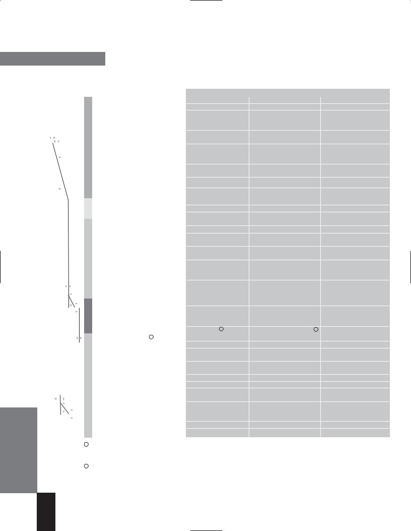
Table 2-2 The table shows which data points from the data dictionary are generated by which CubicleBUS module, enabling you to quickly find out which modules are required for which system.
2/7
WL MODBUS Communication and Electronic Accessories • January 2005
Communication-capable Circuit Breakers
The MODBUS COM16 Module and the BSS
The COM16 module enables the WL Circuit Breaker to exchange data via MODBUS to supervisory systems and MODBUS masters. The COM16 module retrieves some of the key data on the status of the circuit breaker (circuit breaker open/closed, closing spring charged, ready-to- close, etc.) via the CubicleBUS from the BSS (breaker status sensor). Both modules are, therefore, offered together as
a MODBUS communication package.
MODBUS Module COM16
The COM16 module for the WL enables the circuit breaker to be connected to any MODBUS master network. This makes it easy to add WL and a COM16 to existing MODBUS networks.
If required, control/write access to the circuit breaker can be locked using hardware and software to prevent any switching operations
taking place via MODBUS (manual or automatic operation) or parameters from being changed.
All key events are assigned a time stamp from the integrated clock to enable operators to keep track of alarms. This device clock can be synchronized with the clock in the automation system.
A temperature sensor integrated in the COM16 module measures the temperature surrounding the breaker in the switchgear cubicle.
Three integrated microswitches located in the COM16 module are used to detect the position of the circuit breaker (connect, test, disconnect and not present) and communicate via MODBUS. The circuit breaker can be remotely operated only in the test or connect position.
Pin Configuration
The COM16 module is connected to the auxiliary conductor plug-in system at X7.
The electrical connections to the circuit breaker and the CubicleBUS connection to the internal CubicleBUS modules (ETU, BSS, metering function, etc.) are defined in Section 9 of the Operator's Manual and the individual instruction sheets.
WL Circuit Breaker
Interposing relays must be used if the opening and closing solenoids are designed for voltages other than 24V DC.
Terminals X9.1 and X9.2 must be used if the second shunt trip rather than the first shunt trip is used to open the circuit breaker via communication.
The unassigned user output can be used as required and must be connected in the same way as a coupling device (see Graphic 2-4). It can be used, for example, to reset the trip indicator if the remote reset option has been installed. As with Open and Close, only voltages of up to 24V DC are permitted (note the polarity); coupling devices must be used for higher voltages.
The communications line is connected to the 9-pin interface on the front of the COM16 module. The CubicleBUS connection for a RJ45 plug is located at the rear and is used to connect the external CubicleBUS modules. If no external CubicleBUS module is connected, the terminating resistor supplied must be used as an RJ45 plug.
The unassigned user input can be connected using a contact element with the 24V DC from pin 1 to transmit the status of the contact element.
Graphic 2-2 The text on the COM16 module shows the external pin configuration for connecting the closing solenoid and the shunt trips, as well as the MODBUS write protection function and the unassigned input/output.
2/8
WL MODBUS Communication and Electronic Accessories • January 2005
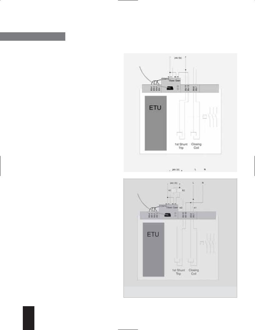
Communication-capable Circuit Breakers
WL Circuit Breaker
MODBUS Write Protection (DPWriteEnable)
Write access via communications can be blocked either temporarily or permanently.
The COM16 module features a hardware input for this purpose. Pin 1 provides the 24V DC supply, which can be connected to pin 2.
If this input is not bridged, write access and control is disabled.
The following actions are blocked if the input of the write-protect function has not been enabled:
•Breaker open/close
•Reset the last trip
•Change the protective parameters
•Change the parameters for the extended protection function (metering function)
•Change the communication parameters
•Settings of the metering options
•Reset maintenance information (counters)
•Force the digital outputs from WinPM.Net
The following control functions are available even if the write protection function has not been enabled:
•Change and set the trigger functions for the waveform buffer
•Read the content of the waveform buffer
•Change the setpoint parameters
•Set/change the system time
•Change the free texts (comments, system IDs)
•Reset the min./max. values
•Change the unassigned user output
MODBUS Installation Guideline
The COM16 must be assembled and connected as described in the WL Operating Instructions. Of particular importance is the requirement to ground the shield of the MODBUS cable.
|
|
|
Graphic |
This diagram illustrates how to wire the COM16 module if MODBUS is to |
|
be used to switch the device open and closed. This diagram only applies |
||
2-3 |
||
to 24V DC control voltage. |
||
|
||
|
|
|
|
|
|
|
|
Graphic |
Interposing relays are required if a control voltage different than 24V DC |
|
|
is used. If the 1st shunt trip is not used to switch off the device, use |
|
|
|
2-4 |
|
|
|
terminals X9.1 and X9.2 to utilize the 2nd shunt trip. |
|
|
|
|
|
|
|
|
|
|
|
|
|
2/9
WL MODBUS Communication and Electronic Accessories • January 2005
Communication-capable Circuit Breakers
WL Circuit Breaker
The write-protect function ensures that all the required information can be transmitted, but prevents any changes to the status of the circuit breaker. Changes can then only be made locally.
Why does the write protection function permit certain actions?
All actions that are not blocked are for remote analysis only and do not have any effect on the current status.
Data Exchange via the COM16 Module
When the COM16 module is configured to exchange data, it is important to note that it is shipped as standard with MODBUS address 126. This can be changed during system configuration (e.g. with the BDA, WinPM.Net, WL Config software or ETU776 display).
The COM16 module has two LEDs (MODBUS and CubicleBUS) for diagnostic purposes. These indicate the operating status of the communication line and the CubicleBUS networks.
Two LEDs are used to determine whether a CubicleBUS module in the circuit breaker is operational. First, the "COMM" LED on the trip unit must be green, that is, the trip unit has recognized at least one other CubicleBUS module. At a minimum, this would only be the Metering Function PLUS if the CubicleBUS was then interrupted. Second, the CubicleBUS LED on the COM16 module must be taken into account. If this is lit with a steady green light, a connection exists from the COM16 module to at least the metering function Plus module.
If both LEDs are green (steady light for CubicleBUS on the COM16 module and COMM on the trip unit), communication is fully established between the trip unit and the COM16 module.
Data is exchanged according to the following principle: an up-to-date copy of all WL Circuit Breaker data (apart from the waveform buffer) is always stored in the COM16 module. A response to a data query from the COM16 module to the supervisory system can, be typically transmitted in just a few milliseconds. Write data from the supervisory system is forwarded to the appropriate addressee on the CubicleBUS.
|
|
|
Figure |
Front view of the MODBUS module for the WL Circuit Breaker with the |
|
MODBUS connection and the two LEDs. The figure below shows a section |
||
2-1 |
||
of the ETU745 and its LEDs for displaying status. |
||
|
||
|
|
|
|
|
Graphic |
Rear view of the COM16 module. The RJ45 connection for the external |
|
CubicleBUS modules can be clearly seen here. If no external CubicleBUS module |
||
2-2 |
||
is connected, the bus must be terminated with the terminating resistor. |
||
|
||
|
|
Meaning |
Position and text on the cable |
CubicleBUS - |
X7.1 |
|
|
CubicleBUS + |
X7.2 |
24V DC + |
X7.3 |
|
|
24V DC ground |
X7.4 |
Table 2-3 The 4 black cables from the COM16 module must be connected to terminal strip X7, which is used to connect the COM16 module to the modules on the CubicleBUS in the circuit breaker.
2/10
WL MODBUS Communication and Electronic Accessories • January 2005

Communication-capable Circuit Breakers
WL Circuit Breaker
MODBUS LED |
Meaning |
Off |
on the COM16 module |
|
|
Red |
Bus error |
|
Communication not possible |
|
No communication with class 1 master |
Green |
MODBUS communication OK |
|
Cyclic data transmission with class 1 master |
|
|
Table 2-4 The MODBUS LED provides information on the state of MODBUS communication in the COM16 module.
CubicleBUS LED |
Meaning |
Off |
No CubicleBUS modules found |
|
|
Red |
CubicleBUS error |
|
|
Green flashing |
CubicleBUS module found, but no metering |
|
function Plus or trip unit |
|
|
Steady green light |
CubicleBUS module found and connection |
|
with the metering function Plus and/or |
|
trip unit |
|
|
Table 2-5 The CubicleBUS LED provides information on the state of CubicleBUS communication in the COM16 module.
Position |
Rear |
Middle |
Front |
|
microswitch |
microswitch |
microswitch |
|
(S46) |
(S47) |
(S48) |
Connect position |
1 |
0 |
0 |
Test position |
0 |
1 |
0 |
|
|
|
|
Disconnect position |
0 |
0 |
1 |
|
|
|
|
Circuit breaker fully withdrawn |
0 |
0 |
0 |
|
|
|
|
Table 2-6 The COM16 module has 3 microswitches for determining the position of the circuit breaker in the guide frame. Depending on which switch is actuated, the position described above is communicated via the comm. system (1=contact closed, 0=contact open).
Three microswitches located in the COM16 module can determine the position of a drawout circuit breaker in the guide frame, which is then communicated via the COM16 module. The positions are defined in Table 2-6. When the position of the circuit breaker has changed, the microswitch that has been actuated
is opened before the next microswitch is actuated. No microswitches are actuated if the breaker is between two of the three positions. The previous state is communicated until a new position is reached when the circuit breaker is moved (see Table 2-6).
There is no way of determining the direction in which the circuit breaker is being moved once the "disconnect position" microswitch has been opened.
When the circuit breaker is initially racked in, the next microswitch to be actuated is the "test position." The COM16 module communicates "circuit breaker not present" until the "test position" key is actuated. The new event message is delayed by 10 seconds to ensure that the breaker is firmly seated.
When the circuit breaker is fully withdrawn, no further microswitches are actuated. "Circuit breaker fully withdrawn" is communicated immediately.
The sequence described above provides hysterisis for communicating contact position and avoids intermittent contact postitions from being communicated.
With UL 489 fixed-mounted circuit breakers, a heel plate is screwed to the COM16 module to transmit operating position.
The COM16 module features a builtin temperature sensor, which is installed outside the circuit breaker, and measures the temperature surrounding the breaker.
It also contains a clock that provides a time stamp for all events, such as minimum and maximum measured values, as well as warnings and trips.
2/11
WL MODBUS Communication and Electronic Accessories • January 2005
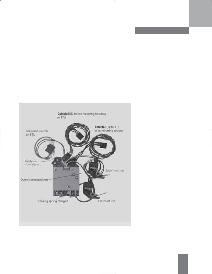
Breaker Status Sensor (BSS)
BSS stands for "breaker status sensor." All microswitches that contain information on the state of the circuit breaker are either installed directly to the BSS or connected to it. The BSS makes this digital information available on the
CubicleBUS.
Communication-capable Circuit Breakers
WL Circuit Breaker
If the status of the circuit breaker in the switchgear is to be displayed or read via communications, the BSS module and the appropriate signaling switch must be installed (if they are not already). The circuit breaker must be installed with an electronic trip unit of type ETU745 or higher.
The BSS can also be field installed.
The BSS indicates the following information:
•Closing spring (charged/discharged)
•Position of the main contacts (open/closed)
•Ready-to-close signal
•Bell Alarm switch on the trip unit (connected to the red mechanical trip indicator)
•Signaling switch on the first shunt trip
•Signaling switch on the second shunt trip
The BSS is included when you order the communications option with with the assembled circuit breaker.
If a BSS is required without communication (e.g. for operating the BDA), it can be ordered seperately.
Figure |
This picture shows the BSS signaling contacts and how they have to be connected. |
|
The BSS is factory installed when the communications option is ordered with the |
||
2-3 |
||
assembled breaker. |
||
|
||
|
|
2/12
WL MODBUS Communication and Electronic Accessories • January 2005
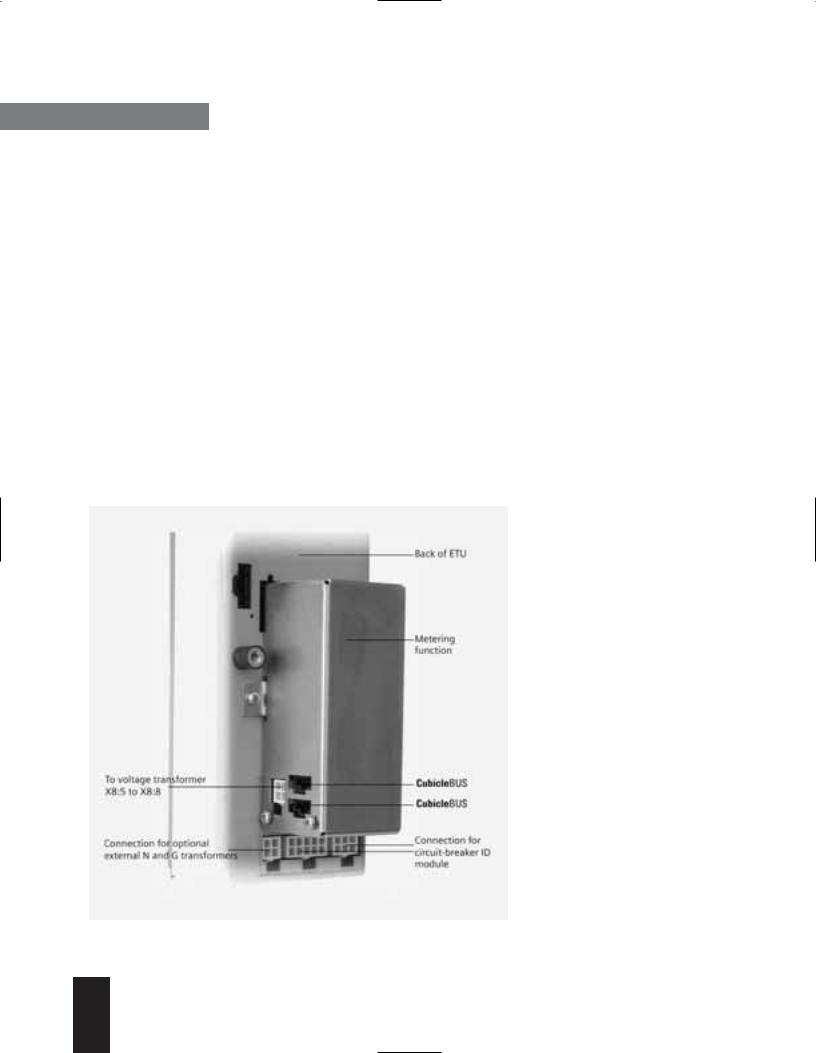
Communication-capable Circuit Breakers
WL Circuit Breaker
Metering Function Plus
The integrated metering function can be used with all trip units with a CubicleBUS connection. It not only extends the range of protection functions of the trip unit but also provides additional warnings and diagnostic options. With its comprehensive range of measured values, the integrated WL Circuit Breaker metering function is an excellent alternative to external multifunction metering devices.
General
In addition to the current values supplied by the trip unit, the metering function provides the measured values in the power distribution system required for Power Management (voltage, power, etc.). With its extended protection function (e.g. undervoltage), the metering function also provides further options for monitoring and protecting the power distribution system.
The option of generating warnings if setpoints are exceeded, speeds up response to system alerts. As a result, the metering function can significantly increase system up-time.
|
|
|
|
|
|
|
|
|
|
Figure |
The Metering Function Plus is located on the back of the trip unit. When ordered as |
|
|
part of an assembled breaker catalog number, it is already installed and ready for |
|
|
|
2-4 |
|
|
|
operation. |
|
|
|
|
|
|
|
|
|
|
|
|
|
2/13
The metering function module is installed on the back of the trip unit (ETU), as shown in Fig. 2-4. The trip unit and metering function module exchange all current data via a highspeed synchronous interface. The metering function module provides all the connected modules (e.g. the COM16 module or BDA) with the parameters for the protective relay functions, the setpoints, measured value settings, and the measured values via the CubicleBUS, so that they can be processed further. Using the two CubicleBUS connections,
the metering function module is connected to the trip unit and either the BSS or directly to X7.
The metering function can be implemented in all circuit breakers with ETU745, ETU755, ETU748 and ETU776. If the Metering Function PLUS module is ordered with the assembled circuit breaker, it will already be installed and ready for operation. The metering function can be retrofitted at any time if the circuit breaker is equipped with one of the trip units listed above. It is simply screwed onto the trip unit and the CubicleBUS lines are snapped in.
Note: If installed by the customer, the metering function is not calibrated with the trip unit; therefore, the accuracy of the specifications in Table 2-7 cannot be guaranteed.
WL MODBUS Communication and Electronic Accessories • January 2005
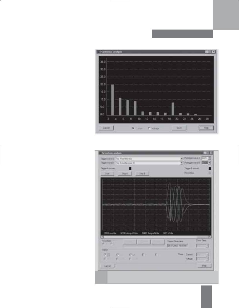
Metering Function Plus
The Metering Function Plus module extends the range of metering functions to include harmonic and waveform analysis.
Harmonic analysis
The Metering Function Plus module senses the current and voltage, saves the measured values, and carries out a fast Fourier transformation. The result is the distribution of the harmonics (in %) up to the 29th harmonic. The calculated values are made available via the CubicleBUS and can be displayed in WinPM.Net and the BDA (see Chapters 3 and 4). They can also be saved as an Excel-compatible *.csv file for subsequent diagnosis. On the ETU776 trip unit, the measured and calculated values can also be displayed.
The harmonic analysis enables not only the quality of the network to be analyzed and logged but also provides settable alarm levels.
Waveform buffer
The Metering Function Plus module features two independent waveform buffers (A and B). Each one has 8 channels, one each for currents Ia, Ib, Ic, IN, and Ig, and voltages Va, Vb, and Vc. Each channel is sensed with a frequency of 1,649 kHz and the values are "pushed" through a shift register (length: 1 second). The process of pushing data through the shift register can be aborted by a configurable trigger event. Trigger events include trips, warnings and setpoint alarms
so that the voltage waveform, for example, can be recorded in the event of undervoltage tripping.
Communication-capable Circuit Breakers
WL Circuit Breaker
|
|
Figure |
The Metering Function Plus analyzes the harmonics. This screenshot from the WinPM.Net |
2-5 |
system shows how the analysis results are displayed. |
|
|
|
|
|
|
|
|
Figure |
Metering Function PLUS can record the current waveform. This can be displayed and |
2-6 |
exported using WinPM.Net. A value of trip current is shown here. |
|
2/14
WL MODBUS Communication and Electronic Accessories • January 2005
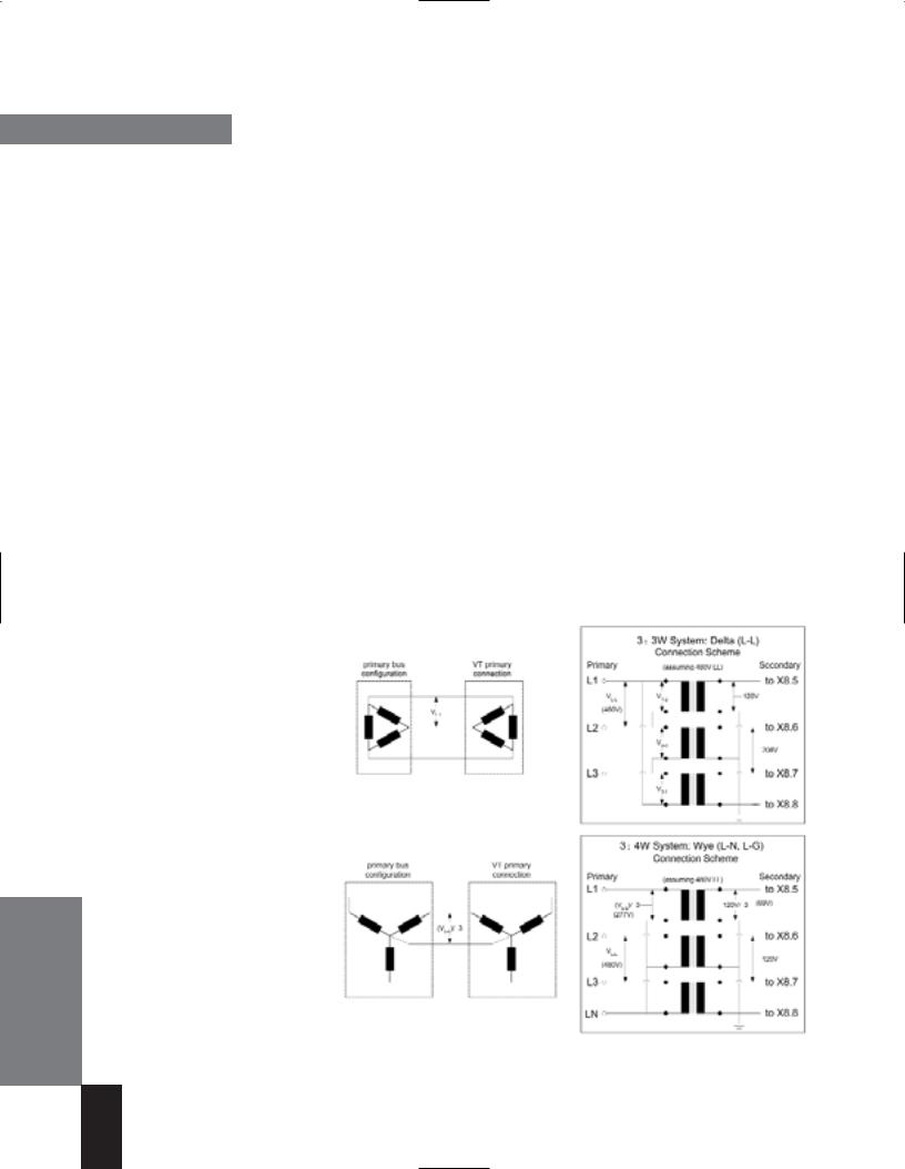
Communication-capable Circuit Breakers
WL Circuit Breaker
The trigger event can be set individually for each waveform buffer. The point at which the trigger event is to take place in the waveform buffer can also be defined. This setting can be used to set the ratio of the pre-event history to the post-event history. If the pre-trigger event history is to be analyzed, the position can be set to 80%. When the event occurs, 0.8 seconds of preevent history and 0.2 seconds of post-event history are available in the waveform buffer, and an existing COM16 module adds a time stamp to the trigger event.
Each waveform buffer stops independently, depending on the trigger event and can be activated again once the analysis is complete.
A large amount of data (approx. 25 kByte for each waveform) can be downloaded and analyzed using WinPM.Net, the BDA and the ETU776 display. Depending on the option,
a range of zoom options and export functions are available.
Voltage Transformers
For isolation reasons, a voltage transformer is used in conjunction with the Metering Function Plus module. This prevents voltage signals of up to 1kV from reaching the ETU directly via the auxiliary secondary connections.
The metering module (“Metering Function Plus”) can be set to expect 3W or 4W (LL/LG) connections and will adjust the amplitude and phase of the signal as necessary.
Three VTs must be used at all times.
All three VTs should be rated for the nominal system L-L voltage (e.g. 480V) and may have either 100V, 110V or 120V secondary voltages.
The following ratios and suggested and equivalent VTs can be used: 240:120 = 2:1
(ITI Part # 460-240 or 468-240) 480:120 = 4:1
(ITI Part # 460-480 or 468-480)
2/15
600:120 = 5:1
(ITI Part # 460-600 or 468-600)
VT Accuracy
Each Metering Module presents a purely resistive (unity power factor) load to the transformer. Assuming no other devices connected to the VT, a ITI type 486 VT can safely feed 10 metering modules and and still maintain 0.6% accuracy assuming the wiring from the VT to the individual metering modules is twisted pair and kept to a minimum length.
This data applies to ambient temperatures from 30ºC to 50ºC and a primary voltage from 80% to 120% Vn.
Maximum distance from voltage transformer
The maximum distance between the metering function and the voltage transformer depends on the cable size and the desired accuracy class.
Metering VT Settings:
Delta/Wye : Delta
VT Primary: 480 (for example)
VT Secondary: 120 (for example)
Metering VT Settings:
Delta/Wye : Delta
VT Primary: 480 (for example)
VT Secondary: 120 (for example)
For a 14AWG cable, the maximum distance should not exceed 50 m for class 0.5 and 100 m for class 3. In areas with high EMC exposure, shielded cable should be used.
Parameters for the settings of the metering function
The trip unit settings which must be made are:
1)VT Primary Voltage (240V, 480V, 600V)
2)VT Secondary Voltage (100V, 110V, 120V)
3)VT Connection (Wye / LG, Delta / LL)
The following tools and functions are available if the parameters have to be changed:
•WinPM.Net
•WL Config
•BDA/BDA Plus
•ETU776 display
Note: Required primary and secondary overcurrent protection (fusing) not shown for clarity.
WL MODBUS Communication and Electronic Accessories • January 2005

Communication-capable Circuit Breakers
WL Circuit Breaker
The metering function provides the following measured values for communication system:
Measured value |
Value range |
Accuracy (with direct order: circuit breaker + |
||
|
|
|
|
trip unit + met. function or met. function Plus)1 |
Currents Ia, Ib, Ic, IN |
30 |
... 8000A |
± 1% |
|
Ground-fault current Ig (measure with external G transformer) |
100 ... 1200A |
± 5% |
||
Line-to-line voltages Vab, Vbc, Vca |
80 |
... 120% Vn |
± 1% |
|
Line-to-neutral voltages Van, Vbn, Vcn |
80 |
... 120% Vn |
± 1% |
|
Average value of phase-to-phase voltages VLLAVG |
80 |
... 120% Vn |
± 1% |
|
Apparent power kVA per phase |
13 |
... 8000kVA |
± 2% |
|
|
|
|
|
|
Total apparent power KVA |
13 |
... 24000kVA |
± 2% |
|
|
|
|
||
Active power kW per phase |
-8000 ... 8000kW |
± 3% (power factor > 0.6) |
||
|
|
|
||
Total active power kWtotal |
-24000 ... 24000kVA |
± 3% (power factor > 0.6) |
||
Reactive power kvar |
-6400 ... 6400kvar |
± 4% (power factor > 0.6) |
||
|
|
|
||
Total reactive power kvar |
-20000 ... 20000kvar |
± 4% (power factor > 0.6) |
||
|
|
|
||
Power factor per phase |
-0.6 ... 1 ... 0.6 |
± 0.04 |
||
|
|
|
||
Power factor total |
-0.6 ... 1 ... 0.6 |
± 0.04 |
||
|
|
|
|
|
Demand of currents Ia, Ib, Ic |
30 |
... 8000A |
± 1% |
|
Average demand of 3-phase current |
30 |
... 8000A |
± 1% |
|
|
|
|
|
|
Demand kWD per phase |
13 |
... 8000kW |
± 3% (power factor > 0.6) |
|
|
|
|
|
|
kW demand 3-phase active power kWD total |
13 |
... 8000kW |
± 3% (power factor > 0.6) |
|
|
|
|
|
|
kVA demand kVA total |
13 |
... 8000kVA |
± 2% |
|
|
|
|
|
|
kVAR demand kVAR per phase |
13 |
... 8000kVA |
± 2% |
|
|
|
|
||
kVAR demand total |
-24000 ... 24000kvar |
± 4% (power factor > 0.6) |
||
|
|
|
|
|
kWhr imported |
1 |
... 10000MWh |
± 2% |
|
|
|
|
|
|
kWhr exported |
1 |
... 10000MWh |
± 2% |
|
|
|
|
|
|
kVARh imported |
1 |
... 10000Mvarh |
± 4% |
|
|
|
|
|
|
kVARh exported |
1 |
... 10000Mvarh |
± 4% |
|
|
|
|
|
|
Frequency |
15 |
... 440 Hz |
± 0.1 Hz |
|
|
|
|
|
|
Total harmonic distortions for current and voltage |
2 |
... 100% |
± 3% from the meas. range up to the 29th harmonic |
|
|
|
|
|
|
Phase unbalance for current and voltage |
2 |
... 150% |
± 1% |
|
|
|
|
|
|
Table 2-7 The metering function provides a minimum and maximum measured value for each measured value specified above. If the metering function is retrofitted by the customer, the accuracy of the values specified cannot be ensured, since it will not have been calibrated with the trip unit.
1.Accuracy is specified as follows: ± (x%) from the upper limit of effective range + 2 LSD (Least Significant Digit)) as shipped from the factory
Measurement conditions: |
|
|
|
|
|
Frequency |
f = 60 Hz |
|
Power supply |
UL Listed 24V DC class 2 |
|
Power factor |
cos |
= 1 |
|
Warm-up period |
2 hours |
Waveform |
Total harmonic distortion≤ 5%; symmetrical load |
Relative air humidity |
Up to 90% |
||
Ambient temperature |
35°C ± 5°C |
|
|
||
|
|
|
|
|
|
Metering range: |
|
|
|
|
|
Current |
0.2 |
... 1.2 |
Inmax |
|
|
Voltage |
0.8 |
... 1.2 |
Vnmax |
|
|
2/16
WL MODBUS Communication and Electronic Accessories • January 2005

Communication-capable Circuit Breakers
WL Circuit Breaker
The extended protective relay functions of the metering function can monitor the following criteria and initiate a trip if values are exceeded.
Protective Relay Function |
ANSI Device Number |
Setting range |
Possible delay |
||
Current unbalance |
46 |
5 ... |
50% |
0 ... |
15 s |
|
|
|
|
|
|
Total harmonic distortion - current |
81THDC |
5 ... |
50% |
5 ... |
15 s |
|
|
|
|
|
|
Voltage unbalance |
47 |
5 ... |
50% |
0 ... |
15 s |
|
|
|
|
|
|
Undervoltage |
27 |
100 |
... 1100V |
0 ... |
15 s |
Overvoltage |
59 |
200 |
... 1200V |
0 ... |
15 s |
|
|
|
|
|
|
Total harmonic distortion - voltage |
81THDV |
5 ... |
50% |
5 ... |
15 s |
|
|
|
|
|
|
Direction of phase rotation |
47N |
- |
|
- |
|
Active power in normal direction |
32 |
13 ... |
4000kW |
0 ... |
15 s |
Active power in reverse direction |
32R |
13 ... |
4000kW |
0 ... |
15 s |
|
|
|
|
|
|
Under frequency |
81U |
40 ... |
70 Hz |
0 ... |
15 s |
|
|
|
|
|
|
Over frequency |
81O |
40 ... |
70 Hz |
0 ... |
15 s |
Table 2-8 Additional trip criteria can be set using the extended protective relay functions. A delay time can be set to prevent transient events from causing nuisance trips: the circuit breaker will not trip unless the condition is present for longer than the delay time.
The metering function supplies the following Alarm Setpoint Functions:
Alarm Function |
Setting range |
Possible delay |
||
Over current |
30 ... |
10000A |
0 ... |
255 s |
|
|
|
|
|
Over current - ground fault |
30 ... |
10000A |
0 ... |
255 s |
|
|
|
|
|
Over current - N-conductor |
30 ... |
10000A |
0 ... |
255 s |
Phase unbalance - current |
5 ... |
50% |
0 ... |
255 s |
Demand - current |
30 ... |
10000A |
0 ... |
255 s |
Total harmonic distortion - current |
5 ... |
50% |
5 ... |
255 s |
Undervoltage |
15 ... |
1200V |
0 ... |
255 s |
Overvoltage |
200 |
... 1200V |
0 ... |
255 s |
Phase unbalance - voltage |
5 ... |
50% |
0 ... |
255 s |
Total harmonic distortion - voltage |
5 ... |
50% |
5 ... |
255 s |
Crest factor |
1 ... |
3,000 |
0 ... |
255 s |
Form factor |
1 ... |
3,000 |
0 ... |
255 s |
Active power in normal direction |
13 ... |
10000kW |
0 ... |
255 s |
Active power in reverse direction |
13 ... |
10000kW |
0 ... |
255 s |
|
|
|
|
|
Leading power factor |
0 ... |
-0.99 |
0 ... |
255 s |
|
|
|
|
|
Lagging power factor |
0 ... |
0.99 |
0 ... |
255 s |
|
|
|
|
|
Demand - active power |
-10000 10000kW... |
0 ... |
255 s |
|
|
|
|
|
|
Apparent power |
13 ... |
10000kVA |
0 ... |
255 s |
|
|
|
|
|
Reactive power in normal direction |
13 ... |
10000kvar |
0 ... |
255 s |
|
|
|
|
|
Reactive power in reverse direction |
13 ... |
10000kvar |
0 ... |
255 s |
|
|
|
|
|
Demand - apparent power |
13 ... |
10000kVA |
0 ... |
255 s |
|
|
|
|
|
Demand - reactive power |
13 ... |
10000kvar |
0 ... |
255 s |
|
|
|
|
|
Underfrequency |
40 ... |
70 Hz |
0 ... |
255 s |
|
|
|
|
|
Overfrequency |
40 ... |
70 Hz |
0 ... |
255 s |
Table 2-9 Alarm and setpoint functions allow events to be generated when system conditions deviate from their nominal values. The generation of the events can be delayed to prevent transient conditions from “chattering”. These alarms are communicated via CubicleBUS and can cause output contacts to close in the configurable output module and can freeze the waveform buffer in the metering function. Alarms are communicated to the COM16/15 where they can be transmitted to the master.
2/17
WL MODBUS Communication and Electronic Accessories • January 2005
 Loading...