


 Loading...
SIMATIC HMI
Touch Panel TP170 A, TP170 B
Operator Panel OP170 B
Equipment Manual
6AV6591-1DC11-1AB0
Release 07/00
Preface, Contents
Introduction |
1 |
|
|
|
|
Functionality |
2 |
|
|
|
|
Commissioning |
3 |
|
|
|
|
Operating Touch Panels |
4 |
|
TP170 A and TP170 B |
||
|
|
|
Operating Keyboard Unit |
5 |
|
OP170 B |
||
|
|
|
Screen Objects for TP170 A |
6 |
|
|
|
|
Screen Objects for TP170 B and |
7 |
|
OP170 B |
||
|
|
|
Recipes for TP170 B and |
8 |
|
OP170 B |
||
|
|
|
System Settings |
9 |
|
|
|
|
Installation |
10 |
|
|
|
|
Unit Description |
11 |
|
|
|
|
Memory Cards for |
12 |
|
TP170 B and OP170 B |
||
|
|
|
Maintenance/Upkeep |
13 |
|
|
|
|
Operating System Update |
14 |
|
A
APPENDICES
E
Glossary, Index

Safety Guidelines
This manual contains notices which you should observe to ensure your own personal safety, as well as to protect the product and connected equipment. These notices are highlighted in the manual by a warning triangle and are marked as follows according to the level of danger:
Warning
!indicates that death, severe personal injury or substantial property damage can result if proper precautions are not taken.
Caution
!indicates that minor personal injury or property damage can result if proper precautions are not taken.
Note
draws your attention to particularly important information on the product, handling the product, or to a particular part of the documentation.
Qualified Personnel
Equipment may be commissioned and operated only by qualified personnel. Qualified personnel within the meaning of the safety notices in this manual are persons who are authorized to commission, ground and identify equipment, systems and circuits in accordance with safety engineering standards.
Correct Usage
Note the following:
Warning
!The equipment may be used only for the applications stipulated in the catalog and in the technical description and only in conjunction with other equipment and components recommended or approved by Siemens.
Startup must not take place until it is established that the machine, which is to accommodate this component, is in conformity with the guideline 89/392/EEC.
Faultless and safe operation of the product presupposes proper transportation, proper storage, erection and installation as well as careful operation and maintenance.
Trademarks
The registered trademarks of Siemens AG are listed in the Preface.
Some of the other designations used in these documents are also registered trademarks; the owner’s rights may be violated if they are used be third parties for their own purposes.
Impressum
Editor and Publisher: A&D PT1.
Copyright Siemens AG 2000 All rights reserved |
Disclaimer of Liability |
The reproduction, transmission or use of this document or its contents is not |
We have checked the contents of this manual for agreement with the hard- |
permitted without express written authority. Offenders will be liable for |
ware and software described. Since deviations cannot be precluded entirely, |
damages. All rights, including rights created by patent grant or registration of |
we cannot guarantee full agreement. However, the data in this manual are |
an utility model or design, are reserved. |
reviewed regularly and any necessary corrections included in subsequent |
|
editions. Suggestions for improvement are welcomed. |
Siemens AG |
|
Automation & Drives |
|
SIMATIC Human Machine Interface |
E Siemens AG 2000 |
Postfach 4848, D-90327 Nuernberg |
Technical data subject to change. |
Index-2 |
TP170 A, TP 170 B, OP170 B Equipment Manual |
Release 07/00 |
|
Siemens Aktiengesellschaft |
Order no: 6AV6591--1DC11--1AB0 |

Preface
This manual
The TP170 A, TP170 B, OP170 B equipment manual is part of the SIMATIC HMI documentation. It provides operation, installation, configuration and maintenance personnel with information concerning installation, functionality, operation and technical design of the SIMATIC operating units TP170 A, TP170 B and OP170 B.
An overview of the entire SIMATIC HMI documentation is provided in Appendix E.
Organization of the manual
The manual is organized into the following chapters:
Chapter |
|
Contents |
|
|
|
|
|
1 |
- 2 |
Overview of the features and functional scope of the unit |
|
|
|
|
|
3 |
- 7 |
Commissioning and operation |
|
|
|
|
|
|
8 |
Recipes for TP170 B and OP170 B |
|
|
|
|
|
|
9 |
System settings |
|
|
|
|
|
10 |
- 13 |
Mechanical and electrical installation, unit description, retrofitting of |
|
|
|
options as well as maintenance and upkeep. |
|
|
|
||
14 |
Informationen on updating the operating system. |
||
|
|
|
|
Appendix |
S |
Technical Data |
|
|
|
S |
Interface Assignments |
|
|
S |
System Messages |
|
|
S |
ESD Guidelines |
|
|
S |
SIMATIC HMI Documentation |
|
|
|
|
TP170 A, TP 170 B, OP170 B Equipment Manual |
i |
Release 07/00 |

Preface
Conventions
The following cionventions are used throughout this manual:
Motor off |
Text in the operating unit display is presented in this |
|
typewriter font. |
Tag |
Symbolic names representing tag values on the screen are |
|
presented in this italic typewriter font. |
Screens |
Functions available for selection are presented in this italic |
|
font. |
ESC |
The names of keys and buttons are displayed in a different |
|
font. |
History
The various releases of this manual correspond to the following versions of the ProTool CS configuration software:
Edition |
Comment |
ProTool Version |
|
|
|
12/99 |
First release of the TP170 A equipment |
From V5.2 |
|
manual |
|
|
|
|
07/00 |
Extensions to the TP170 B and OP170 B |
From V5.2 + SP2 |
|
units |
|
|
|
|
Trademarks
The following names are registered trademarks of the Siemens AG:
S |
SIMATICR |
S |
SIMATIC HMIR |
S |
HMIR |
S |
ProToolR |
S |
ProTool/LiteR |
S |
ProTool/ProR |
S SIMATIC Multi PanelR |
|
S SIMATIC Multifunctional PlatformR |
|
S |
MP 270R |
S |
ProAgentR |
ii |
TP170 A, TP 170 B, OP170 B Equipment Manual |
Release 07/00 |

Preface
Other support
In the case of technical queries, please contact the Siemens representatives in the subsidiaries and branches responsible for your area.
SIMATIC Customer Support Hotline
Available worldwide, at all times:
Nuernberg
Johnson City
Singapur
|
|
|
SIMATIC Basic Hotline |
|
|
|
|
Nuernberg |
|
|
Johnson City |
|
Singapur |
|
|
|
|
|
|
||||
SIMATIC BASIC Hotline |
|
SIMATIC BASIC Hotline |
|
SIMATIC BASIC Hotline |
|||
Local time |
Mo - Fr 7:00 to 17:00 |
|
Local time |
Mo - Fr 8:00 to 19:00 |
|
Local time |
Mo - Fr 8:30 to 17:30 |
Telephone: |
+49 (911) 895-7000 |
|
Telephone: |
+1 423 461-2522 |
|
Telephone: |
+65 740-7000 |
Fax: |
+49 (911) 895-7002 |
|
Fax: |
+1 423 461-2231 |
|
Fax: |
+65 740-7001 |
E-Mail: |
simatic.support@ |
|
E-Mail: |
simatic.hotline@ |
|
E-Mail: |
simatic.hotline@ |
|
nbgm.siemens.de |
|
|
sea.siemens.com |
|
|
sae.siemens.com.sg |
SIMATIC Premium Hotline |
|
|
|
|
|
|
|
|
|
|
|
|
|
||
(charged, only with SIMATIC Card) |
|
|
|
|
|
|
|
Time: |
Mo - Fr 0:00 to 24:00 |
|
|
|
|
|
|
Telephone: |
+49 (911) 895-7777 |
|
|
|
|
|
|
Fax: |
+49 (911) 895-7001 |
|
|
|
|
|
|
TP170 A, TP 170 B, OP170 B Equipment Manual |
iii |
Release 07/00 |

Preface
SIMATIC Customer Online Services
SIMATIC Customer Support offers comprehensive additional information concerning SIMATIC products through its Online services as follows:
SUp-to-date general information is provided
--in Internet under http://www.ad.siemens.de/simatic
--via the Fax-Polling under 08765-93 02 77 95 00
SUp-to-date product information and downloads for practical use can be found: -- in Internet under http://www.ad.siemens.de/support/html-00/
Abbreviations
The abbreviations used in this user’s guide have the following meaning:
AG (PLC) |
Programmable Logic Controller |
AM |
Alarm Message |
ANSI |
American National Standards Institute |
AS 511 |
Protocol of the PU interface to SIMATIC S5 |
ASCII |
American Standard Code for Information Interchange |
CCFL |
Cold Cathode Fluorescence Lamp |
CF |
Compact Flash |
CPU |
Central Processing Unit |
CSV |
Comma Separated Values |
DP |
Decentralized Periphery |
DRAM |
Dynamic Random Access Memory |
DSN |
Data Source Name |
ESD |
Electrostatically Sensitive Device |
EM |
Event Message |
EMC |
Electromagnetic compatibility |
HMI |
Human Machine Interface |
IF |
Interface |
LCD |
Liquid Crystal Display |
LED |
Light Emitting Diode |
MP |
Multi Panel |
MPI |
Multipoint Interface (SIMATIC S7) |
OP |
Operator Panel |
PC |
Personal Computer |
PCL |
Printer Control Language |
PLC |
Programmable Logic Controller |
iv |
TP170 A, TP 170 B, OP170 B Equipment Manual |
Release 07/00 |

Preface
PU |
Programming Unit |
PPI |
Point to Point Interface (SIMATIC S7) |
RAM |
Random Access Memory |
SRAM |
Static Random Access Memory |
STN |
Super Twisted Nematic |
TCP/IP |
Transmission Control Protocol/Internet Protocol |
TFT |
Thin Film Transistor |
TTL |
Transistor--Transistor Logic |
TP |
Touch Panel |
A list of all the specialist terms together with their explanations is provided in the Glossary at the end of this guide.
TP170 A, TP 170 B, OP170 B Equipment Manual |
v |
Release 07/00 |
Preface
vi |
TP170 A, TP 170 B, OP170 B Equipment Manual |
Release 07/00 |

Contents
1 |
Introduction . . . . . . . . . . . . . . . . . . . . . . . . . . . . . . . . . . . . . . . . . . . . . . . . . . . . . . . . . . . . |
1-1 |
|
2 |
Functionality . . . . . . . . . . . . . . . . . . . . . . . . . . . . . . . . . . . . . . . . . . . . . . . . . . . . . . . . . . . |
2-1 |
|
3 |
Commissioning . . . . . . . . . . . . . . . . . . . . . . . . . . . . . . . . . . . . . . . . . . . . . . . . . . . . . . . . |
3-1 |
|
|
3.1 |
Initial Startup . . . . . . . . . . . . . . . . . . . . . . . . . . . . . . . . . . . . . . . . . . . . . . . . . . . |
3-3 |
|
3.2 |
Recommissioning . . . . . . . . . . . . . . . . . . . . . . . . . . . . . . . . . . . . . . . . . . . . . . . |
3-4 |
|
3.3 |
Options for Download Mode . . . . . . . . . . . . . . . . . . . . . . . . . . . . . . . . . . . . . . |
3-6 |
|
3.4 |
Testing a Project on the Operating Unit . . . . . . . . . . . . . . . . . . . . . . . . . . . . . |
3-10 |
|
3.5 |
Download Back (TP170 B and OP170 B) . . . . . . . . . . . . . . . . . . . . . . . . . . . |
3-12 |
|
3.6 |
Backup/Restore the Internal Flash Memory |
|
|
|
(TP170 B and OP170 B) . . . . . . . . . . . . . . . . . . . . . . . . . . . . . . . . . . . . . . . . . |
3-14 |
4 |
Operating Touch Panels TP170 A and TP170 B . . . . . . . . . . . . . . . . . . . . . . . . . . . |
4-1 |
|
|
4.1 |
Operating Touch Elements . . . . . . . . . . . . . . . . . . . . . . . . . . . . . . . . . . . . . . . . |
4-1 |
|
4.1.1 |
Enter Numeric Values . . . . . . . . . . . . . . . . . . . . . . . . . . . . . . . . . . . . . . . . . . . . |
4-3 |
|
4.1.2 |
Enter Alphanumeric Values . . . . . . . . . . . . . . . . . . . . . . . . . . . . . . . . . . . . . . . |
4-5 |
|
4.1.3 |
Enter Symbolic Values on the TP170 B . . . . . . . . . . . . . . . . . . . . . . . . . . . . . |
4-7 |
|
4.2 |
Calling in Help Text on the TP170 B . . . . . . . . . . . . . . . . . . . . . . . . . . . . . . . . |
4-8 |
5 |
Operating Keyboard Unit OP170 B . . . . . . . . . . . . . . . . . . . . . . . . . . . . . . . . . . . . . . . |
5-1 |
|
|
5.1 |
Integrated Keyboard . . . . . . . . . . . . . . . . . . . . . . . . . . . . . . . . . . . . . . . . . . . . . |
5-1 |
|
5.2 |
Key Combinations . . . . . . . . . . . . . . . . . . . . . . . . . . . . . . . . . . . . . . . . . . . . . . . |
5-5 |
|
5.3 |
Entering Values . . . . . . . . . . . . . . . . . . . . . . . . . . . . . . . . . . . . . . . . . . . . . . . . . |
5-7 |
|
5.3.1 |
Enter Numeric Values . . . . . . . . . . . . . . . . . . . . . . . . . . . . . . . . . . . . . . . . . . . . |
5-8 |
|
5.3.2 |
Enter Alphanumeric Values . . . . . . . . . . . . . . . . . . . . . . . . . . . . . . . . . . . . . . . |
5-9 |
|
5.3.3 |
Enter Symbolic Values . . . . . . . . . . . . . . . . . . . . . . . . . . . . . . . . . . . . . . . . . . . |
5-10 |
|
5.4 |
Call Help Text . . . . . . . . . . . . . . . . . . . . . . . . . . . . . . . . . . . . . . . . . . . . . . . . . . . |
5-11 |
TP170 A, TP 170 B, OP170 B Equipment Manual |
vii |
Release 07/00 |

Contents
6 |
Screen Objects for TP170 A . . . . . . . . . . . . . . . . . . . . . . . . . . . . . . . . . . . . . . . . . . . . . |
6-1 |
|
|
6.1 |
General Operation . . . . . . . . . . . . . . . . . . . . . . . . . . . . . . . . . . . . . . . . . . . . . . . |
6-2 |
|
6.1.1 |
Operating Screens . . . . . . . . . . . . . . . . . . . . . . . . . . . . . . . . . . . . . . . . . . . . . . |
6-2 |
|
6.1.2 |
Logging On and Off from the Operating Unit . . . . . . . . . . . . . . . . . . . . . . . . |
6-3 |
|
6.2 |
Overview of Screen Objects . . . . . . . . . . . . . . . . . . . . . . . . . . . . . . . . . . . . . . |
6-4 |
|
6.3 |
Input Field for Date/Time . . . . . . . . . . . . . . . . . . . . . . . . . . . . . . . . . . . . . . . . . |
6-5 |
|
6.4 |
Input Field for Confidential Password Entry . . . . . . . . . . . . . . . . . . . . . . . . . |
6-5 |
|
6.5 |
Status Button . . . . . . . . . . . . . . . . . . . . . . . . . . . . . . . . . . . . . . . . . . . . . . . . . . . |
6-6 |
|
6.6 |
Messages . . . . . . . . . . . . . . . . . . . . . . . . . . . . . . . . . . . . . . . . . . . . . . . . . . . . . . |
6-7 |
|
6.7 |
Bar graphs . . . . . . . . . . . . . . . . . . . . . . . . . . . . . . . . . . . . . . . . . . . . . . . . . . . . . |
6-9 |
7 |
Screen Objects for TP170 B and OP170 B . . . . . . . . . . . . . . . . . . . . . . . . . . . . . . . . |
7-1 |
|
|
7.1 |
General Operation . . . . . . . . . . . . . . . . . . . . . . . . . . . . . . . . . . . . . . . . . . . . . . . |
7-2 |
|
7.1.1 |
Operating screens . . . . . . . . . . . . . . . . . . . . . . . . . . . . . . . . . . . . . . . . . . . . . . . |
7-2 |
|
7.1.2 |
Logging On and Off from the Operating Unit . . . . . . . . . . . . . . . . . . . . . . . . |
7-5 |
|
7.2 |
Overview of Screen Objects . . . . . . . . . . . . . . . . . . . . . . . . . . . . . . . . . . . . . . |
7-6 |
|
7.3 |
Input Field for Date/Time . . . . . . . . . . . . . . . . . . . . . . . . . . . . . . . . . . . . . . . . . |
7-9 |
|
7.4 |
Input Field for Confidential Password Entry . . . . . . . . . . . . . . . . . . . . . . . . . |
7-9 |
|
7.5 |
Buttons . . . . . . . . . . . . . . . . . . . . . . . . . . . . . . . . . . . . . . . . . . . . . . . . . . . . . . . . |
7-10 |
|
7.6 |
Status Button . . . . . . . . . . . . . . . . . . . . . . . . . . . . . . . . . . . . . . . . . . . . . . . . . . . |
7-11 |
|
7.7 |
Switch . . . . . . . . . . . . . . . . . . . . . . . . . . . . . . . . . . . . . . . . . . . . . . . . . . . . . . . . . |
7-13 |
|
7.8 |
Messages . . . . . . . . . . . . . . . . . . . . . . . . . . . . . . . . . . . . . . . . . . . . . . . . . . . . . . |
7-14 |
|
7.8.1 |
ALARM_S . . . . . . . . . . . . . . . . . . . . . . . . . . . . . . . . . . . . . . . . . . . . . . . . . . . . . . |
7-16 |
|
7.8.2 |
Message Line . . . . . . . . . . . . . . . . . . . . . . . . . . . . . . . . . . . . . . . . . . . . . . . . . . . |
7-17 |
|
7.8.3 |
Message Window . . . . . . . . . . . . . . . . . . . . . . . . . . . . . . . . . . . . . . . . . . . . . . . |
7-17 |
|
7.8.4 |
Message Page . . . . . . . . . . . . . . . . . . . . . . . . . . . . . . . . . . . . . . . . . . . . . . . . . . |
7-19 |
|
7.8.5 |
Message Buffer . . . . . . . . . . . . . . . . . . . . . . . . . . . . . . . . . . . . . . . . . . . . . . . . . |
7-20 |
|
7.8.6 |
Message View . . . . . . . . . . . . . . . . . . . . . . . . . . . . . . . . . . . . . . . . . . . . . . . . . . |
7-21 |
|
7.8.7 |
Simple Message View . . . . . . . . . . . . . . . . . . . . . . . . . . . . . . . . . . . . . . . . . . . |
7-23 |
|
7.9 |
Bar Graphs . . . . . . . . . . . . . . . . . . . . . . . . . . . . . . . . . . . . . . . . . . . . . . . . . . . . . |
7-24 |
|
7.10 |
Trend View . . . . . . . . . . . . . . . . . . . . . . . . . . . . . . . . . . . . . . . . . . . . . . . . . . . . . |
7-25 |
|
7.11 |
Date/Time . . . . . . . . . . . . . . . . . . . . . . . . . . . . . . . . . . . . . . . . . . . . . . . . . . . . . . |
7-27 |
|
7.12 |
Password List . . . . . . . . . . . . . . . . . . . . . . . . . . . . . . . . . . . . . . . . . . . . . . . . . . |
7-28 |
8 |
Recipes for TP170 B and OP170 B . . . . . . . . . . . . . . . . . . . . . . . . . . . . . . . . . . . |
. . . . 8-1 |
|
|
8.1 |
Overview . . . . . . . . . . . . . . . . . . . . . . . . . . . . . . . . . . . . . . . . . . . . . . . . . . . |
. . . . 8-1 |
|
8.2 |
Recipe Configuration . . . . . . . . . . . . . . . . . . . . . . . . . . . . . . . . . . . . . . . . . |
. . . 8-3 |
|
8.3 |
Editing Data Records . . . . . . . . . . . . . . . . . . . . . . . . . . . . . . . . . . . . . . . . . |
. . . 8-5 |
|
8.3.1 |
Recipe View . . . . . . . . . . . . . . . . . . . . . . . . . . . . . . . . . . . . . . . . . . . . . . . . . |
. . . 8-6 |
|
8.3.2 |
Recipe Screens . . . . . . . . . . . . . . . . . . . . . . . . . . . . . . . . . . . . . . . . . . . . . . |
. . . 8-14 |
|
8.3.3 |
Functions and PLC jobs . . . . . . . . . . . . . . . . . . . . . . . . . . . . . . . . . . . . . . . |
. . . 8-16 |
|
8.3.4 |
Import/Export Data Records . . . . . . . . . . . . . . . . . . . . . . . . . . . . . . . . . . . |
. . . 8-17 |
|
8.3.5 |
Reaction on Changing the Recipe Structure . . . . . . . . . . . . . . . . . . . . . |
. . . 8-20 |
viii |
|
TP170 A, TP 170 B, OP170 B Equipment Manual |
|
|
|
Release 07/00 |
|
Contents
9 |
System Settings . . . . . . . . . . . . . . . . . . . . . . . . . . . . . . . . . . . . . . . . . . . . . . . . . . . . . . . . |
9-1 |
|
|
9.1 |
TP170 A Settings . . . . . . . . . . . . . . . . . . . . . . . . . . . . . . . . . . . . . . . . . . . . . . . |
9-2 |
|
9.1.1 |
Setting an Operating Mode . . . . . . . . . . . . . . . . . . . . . . . . . . . . . . . . . . . . . . . |
9-2 |
|
9.1.2 |
Screen Settings . . . . . . . . . . . . . . . . . . . . . . . . . . . . . . . . . . . . . . . . . . . . . . . . . |
9-3 |
|
9.1.3 |
Set Screen Saver Response Time . . . . . . . . . . . . . . . . . . . . . . . . . . . . . . . . . |
9-5 |
|
9.2 |
Settings for TP170 B and OP170 B . . . . . . . . . . . . . . . . . . . . . . . . . . . . . . . . |
9-6 |
|
9.2.1 |
Set Language . . . . . . . . . . . . . . . . . . . . . . . . . . . . . . . . . . . . . . . . . . . . . . . . . . . |
9-6 |
|
9.2.2 |
Setting an Operating Mode . . . . . . . . . . . . . . . . . . . . . . . . . . . . . . . . . . . . . . . |
9-7 |
|
9.2.3 |
Screen Settings . . . . . . . . . . . . . . . . . . . . . . . . . . . . . . . . . . . . . . . . . . . . . . . . . |
9-8 |
|
9.2.4 |
Control Panel Settings . . . . . . . . . . . . . . . . . . . . . . . . . . . . . . . . . . . . . . . . . . . |
9-10 |
10 |
Installation . . . . . . . . . . . . . . . . . . . . . . . . . . . . . . . . . . . . . . . . . . . . . . . . . . . . . . . . . . . . . |
10-1 |
|
|
10.1 |
Mechanical Installation . . . . . . . . . . . . . . . . . . . . . . . . . . . . . . . . . . . . . . . . . . . |
10-2 |
|
10.2 |
Electrical Installation . . . . . . . . . . . . . . . . . . . . . . . . . . . . . . . . . . . . . . . . . . . . . |
10-5 |
|
10.2.1 |
Connect Configuration Computer . . . . . . . . . . . . . . . . . . . . . . . . . . . . . . . . . . |
10-7 |
|
10.2.2 |
Connect PLC . . . . . . . . . . . . . . . . . . . . . . . . . . . . . . . . . . . . . . . . . . . . . . . . . . . |
10-8 |
|
10.2.3 |
Connecting a Printer to TP170 B and OP170 B . . . . . . . . . . . . . . . . . . . . . . |
10-11 |
11 |
Unit Description . . . . . . . . . . . . . . . . . . . . . . . . . . . . . . . . . . . . . . . . . . . . . . . . . . . . . . . . |
11-1 |
|
|
11.1 |
TP170 A . . . . . . . . . . . . . . . . . . . . . . . . . . . . . . . . . . . . . . . . . . . . . . . . . . . . . . . |
11-2 |
|
11.1.1 |
Dimensions and mounting area . . . . . . . . . . . . . . . . . . . . . . . . . . . . . . . . . . . . |
11-2 |
|
11.1.2 |
Connection elements . . . . . . . . . . . . . . . . . . . . . . . . . . . . . . . . . . . . . . . . . . . . |
11-3 |
|
11.1.3 |
Communication options . . . . . . . . . . . . . . . . . . . . . . . . . . . . . . . . . . . . . . . . . . |
11-4 |
|
11.2 |
TP170 B . . . . . . . . . . . . . . . . . . . . . . . . . . . . . . . . . . . . . . . . . . . . . . . . . . . . . . . |
11-5 |
|
11.2.1 |
Dimensions and mounting area . . . . . . . . . . . . . . . . . . . . . . . . . . . . . . . . . . . . |
11-5 |
|
11.2.2 |
Connection elements . . . . . . . . . . . . . . . . . . . . . . . . . . . . . . . . . . . . . . . . . . . . |
11-6 |
|
11.2.3 |
Communication options . . . . . . . . . . . . . . . . . . . . . . . . . . . . . . . . . . . . . . . . . . |
11-7 |
|
11.3 |
OP170 B . . . . . . . . . . . . . . . . . . . . . . . . . . . . . . . . . . . . . . . . . . . . . . . . . . . . . . . |
11-8 |
|
11.3.1 |
Dimensions and Mounting Area . . . . . . . . . . . . . . . . . . . . . . . . . . . . . . . . . . . |
11-8 |
|
11.3.2 |
Connection Elements . . . . . . . . . . . . . . . . . . . . . . . . . . . . . . . . . . . . . . . . . . . . |
11-9 |
|
11.3.3 |
Communication Options . . . . . . . . . . . . . . . . . . . . . . . . . . . . . . . . . . . . . . . . . . |
11-10 |
|
11.3.4 |
Labeling Function Keys (OP170 B) . . . . . . . . . . . . . . . . . . . . . . . . . . . . . . . . |
11-10 |
12 |
Memory card for TP170 B and OP170 B . . . . . . . . . . . . . . . . . . . . . . . . . . . . . . . . . . |
12-1 |
|
13 |
Maintenance/Upkeep . . . . . . . . . . . . . . . . . . . . . . . . . . . . . . . . . . . . . . . . . . . . . . . . . . . . |
13-1 |
|
|
Clean Screen/Keyboard . . . . . . . . . . . . . . . . . . . . . . . . . . . . . . . . . . . . . . . . . . . . . . . . . . |
13-1 |
|
14 |
Operating System Update . . . . . . . . . . . . . . . . . . . . . . . . . . . . . . . . . . . . . . . . . . . . . . . |
14-1 |
|
Appendices
A |
Technical Data . . . . . . . . . . . . . . . . . . . . . . . . . . . . . . . . . . . . . . . . . . . . . . . . . . . . . . . . . |
A-1 |
B |
Interface Assignment . . . . . . . . . . . . . . . . . . . . . . . . . . . . . . . . . . . . . . . . . . . . . . . . . . . |
B-1 |
C |
System Messages . . . . . . . . . . . . . . . . . . . . . . . . . . . . . . . . . . . . . . . . . . . . . . . . . . . . . . |
C-1 |
D |
ESD Guidelines . . . . . . . . . . . . . . . . . . . . . . . . . . . . . . . . . . . . . . . . . . . . . . . . . . . . . . . . |
D-1 |
E |
SIMATIC HMI Documentation . . . . . . . . . . . . . . . . . . . . . . . . . . . . . . . . . . . . . . . . . . . . |
E-1 |
TP170 A, TP 170 B, OP170 B Equipment Manual |
ix |
Release 07/00 |
Contents
x |
TP170 A, TP 170 B, OP170 B Equipment Manual |
Release 07/00 |

Introduction |
1 |
Low-end units
The Touch Panels TP170 A and TP170 B, and Operator Panel OP170 B represent products in the new series of low-end operating units. The units in this series are based on the innovative standard WindowsR CE operating system. They complete the SIMATIC HMI product range in the low-end sector. The TP170 A is a low-price initial unit which can operate with all SIMATIC S7 CPUs. The TP170 B and OP170 B fulfill all sophisticated functional requirements.
This new product series enables self-created graphics, digital photos and scanned screens to be integrated in a project. Bars and trend curve diagrams can still be used to graphically display temperature progressions, for example.
The units are equipped with an interface for MPI and PROFIBUS-DP. This interface is also used for downloading configurations. The unit memories are designed for small to medium-size configurations.
Here is a short selection of common features:
S Automatic transfer detection for downloading configurations S Password protection
S Input/Output fields to display and modify process parameters
SConfigurable buttons and function keys (OP170 B) to control input/output and data bits
S Bars for the graphical dsplay of dynamic values
S Standard library for graphics and buttons can be used under ProTool CS
SGraphics can be configured to label buttons or as format-filling background screens
SFixed text for labeling buttons, process screens or process values in any character size
Additional features with TP170 B and OP170 B:
S |
Print functions |
S |
Trends |
S |
Scheduler |
S |
Recipe management |
S Backing up recipe data and configurations on optional memory cards (CF card) A complete overview of the functional range of the units is provided Chapter 2.
TP170 A, TP 170 B, OP170 B Equipment Manual |
1-1 |
Release 07/00 |

Introduction
Area of use of the units
The units have been conceived for easy machine operation and monitoring. They provide a realistic graphical representation of the machine or system to be monitored. Their area of use include implementation in machine and apparatus construction as well as in the packing and electronics industry.
The high degree of protection (IP65 on the front side) and non-implementation of moving storage media, such as hard disks and floppy disks, ensure the operating units are also suitable for use in rough industrial environments and directly on site on the respective machine.
Installation locations for the units include: S Panels
S Consoles
As a result of their minimum installation depth, the units are particularly suited for operation near the machine.
Easy to operate and observe
The units enable operating statuses, current process values and errors concerning a connected PLC to be graphically displayed and the relevant machine or system to be easily monitored and operated. Display and operation of the units can be adapted optimally for the respective process requirements by using the configuration software ProTool CS.
The units can be used to:
Scontrol and monitor the process by means of the menu system. Setpoint values or control element settings, for instance, can be modified by entering values or activating configured function keys;
S display processes, machines and systems on full-graphic, dynamic screens;
Sdisplay and edit messages and, for example, process tags in output fields, and to visualize bars or status display;
Sto intervene directly in processes via the Touch Screen (TP170 A, TP170 B) or using the integrated keyboard (OP170 B).
1-2 |
TP170 A, TP 170 B, OP170 B Equipment Manual |
Release 07/00 |
Introduction
Configuring using ProTool/Pro CS, ProTool and ProTool/Lite
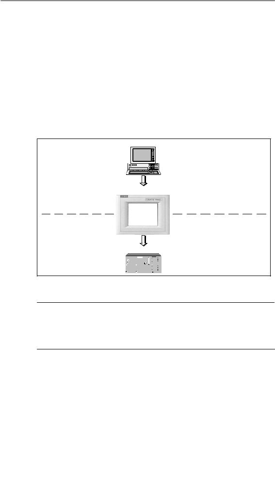
Graphics, texts and operating and display elements which need to be represented on the operating units must first be created on a configuration computer (PC or PU) using the configuration software SIMATIC ProTool/Pro CS, ProTool or ProTool/Lite. The configuration computer must be connected to the operating unit in order to download the project to the operating unit (refer to “Configuration phase” in Figure 1-1).
Once the project has been successfully downloaded, connect the operating unit to the PLC. The operating unit can then communicate with the PLC and respond according to the information configured for running the program in the PLC (refer to “Process control phase” in Figure 1-1).
PC/PU
Configuration phase |
Create project data |
|
Save project data |
||
|
||
|
Test project |
|
|
Simulate project |
|
|
Download project data |
TP170 A / TP170 B / OP170 B
Connected to PLC
PLC
Process running phase
Figure 1-1 Configuration and process running phase
Note
The units can be configured, as required, using the configuration software ProTool/Pro CS, ProTool or ProTool/Lite. Throughout this manual, the term ProTool CS (CS: Configuration System) is used to represent all three software variants.
TP170 A, TP 170 B, OP170 B Equipment Manual |
1-3 |
Release 07/00 |
Introduction
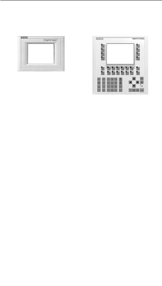
Overview of units
TP170 A, TP170 B |
OP170 B |
|
|||
|
|
|
|
|
|
|
|
TP170 A |
TP170 B |
|
OP170 B |
|
|
|
|
|
|
Processor |
Type |
|
32 bit RISC |
|
|
|
|
|
|
||
Memory |
Memory for configuration |
256 kByte |
512 kByte |
||
|
|
|
|
||
Software |
Operating system |
MicrosoftR WindowsR CE |
|||
|
|
|
|
|
|
Ser. interface 1 |
Physics |
1 ´ RS232 (9-pin) |
|
||
|
|
1 ´ RS422/RS485 |
|
||
|
|
|
|
||
|
S7 connection |
MPI/PROFIBUS-DP |
|||
|
|
|
|
||
|
Max. baud rate |
1.5 MB |
12 MB |
||
|
|
|
|
||
Ser. interface 2 |
|
– |
RS232 |
||
|
|
|
|
|
|
Display |
Active screen area (W ´ H) in |
|
211 ´ 158 (6’’) |
|
|
|
mm |
|
|
|
|
|
|
|
|
|
|
|
Resolution (pixels) |
|
320 ´ 240 |
|
|
|
|
|
|
|
|
|
Colors |
4 Blue Mode |
4 Blue Mode |
|
4 Blue Mode |
|
|
|
or |
|
|
|
|
|
16 colors |
|
|
|
|
|
|
|
|
Operating elements |
Touch Screen |
|
|
|
– |
|
|
|
|
|
|
|
Matrix keyboard |
– |
|
|
|
|
|
|
|
|
|
|
Function keys with configurable |
– |
|
|
24 |
|
functions |
|
|
|
(18 with |
|
|
|
|
|
LEDs) |
|
|
|
|
|
|
|
Those usable as softkeys |
– |
|
|
14 |
|
|
|
|
|
|
|
Labeling the function keys |
– |
|
|
System- |
|
|
|
|
|
specific with |
|
|
|
|
|
labelling |
|
|
|
|
|
strips |
|
|
|
|
|
|
Special features |
S External memory extension: |
|
|
|
|
|
-- Slot for CF card |
– |
|
|
|
|
|
|
|
|
|
1-4 |
TP170 A, TP 170 B, OP170 B Equipment Manual |
Release 07/00 |

Introduction
Further information
Detailed information on the technical data of the operating units is provided in Appendix A of this manual.
Detailed descriptions of the creation of projects for the operating unit and configuration software functions are provided in the ProTool Configuring Windows-based Systems user’s guide and in the online help for ProTool CS.
Connection of the operating unit to the PLC is described in the Communication for Windows-based Systems user’s manual.
Any new information which could not be taken into account for printing in the guides is provided in the Readme.wri file on the ProTool CD.
TP170 A, TP 170 B, OP170 B Equipment Manual |
1-5 |
Release 07/00 |
Introduction
1-6 |
TP170 A, TP 170 B, OP170 B Equipment Manual |
Release 07/00 |

Functionality |
2 |
The table below summarizes the functional scope of the operating units. The values specified are the maximum values which can be managed by the units. The values are limited by the size of the memory used.
|
Function |
TP170 A |
TP170 B |
|
OP170 B |
|
|
|
|
|
|
|
|
Event messages |
|
Number |
100 |
400 |
1) |
|
|
|
|
|
|
||
|
|
Display |
Message view |
Message line, message window/ |
||
|
|
|
|
message page, message view |
||
|
|
|
|
|
||
|
|
View all queued |
Message view |
Message page/Message view |
||
|
|
messages |
|
|
|
|
|
|
|
|
|
|
|
|
|
Message length per line |
|
70 characters |
|
|
|
|
|
|
|
|
|
|
|
Process values in |
|
8 |
|
|
|
|
message text |
|
|
|
|
|
|
|
|
|
|
|
|
|
Edit messages |
– |
|
|
|
|
|
|
|
|
||
Alarm messages |
|
Number |
– |
4001) |
||
|
|
Display |
– |
Message |
|
Message line/ |
|
|
|
|
window/ |
|
message |
|
|
|
|
message page/ |
|
window/ |
|
|
|
|
message view |
|
message |
|
|
|
|
|
|
page/message |
|
|
|
|
|
|
view |
|
|
|
|
|
|
|
|
|
Type of display |
– |
first/last, selectable |
||
|
|
|
|
|
||
|
|
View all queued |
– |
In message page/message view |
||
|
|
messages |
|
|
|
|
|
|
|
|
|
||
|
|
Message length per line |
– |
70 characters |
||
|
|
|
|
|
|
|
|
|
Process values in |
– |
8 |
|
|
|
|
message text |
|
|
|
|
|
|
|
|
|
|
|
|
|
Acknowledge individual |
– |
|
|
|
|
|
alarm messages |
|
|
|
|
|
|
|
|
|
||
|
|
Acknowledge several |
– |
16 acknowledgment groups |
||
|
|
alarm messages |
|
|
|
|
|
|
simultaneously (group |
|
|
|
|
|
|
acknowledgement) |
|
|
|
|
|
|
|
|
|
|
|
|
|
Edit messages |
– |
|
|
|
|
|
|
|
|
|
|
TP170 A, TP 170 B, OP170 B Equipment Manual |
2-1 |
Release 07/00 |

Functionality
Function |
TP170 A |
TP170 B |
|
OP170 B |
||
|
|
|
|
|
|
|
ALARM_S |
Display S7 messages |
– |
|
|
||
|
|
|
|
|
|
|
Message logging |
Output to printer |
– |
|
|
||
|
|
|
|
|
||
Volatile message |
Capacity |
– |
128 message events |
|||
buffer |
|
|
|
|
|
|
View event/alarm |
–/– |
|
/ |
|||
|
|
|||||
|
messages |
|
|
|
|
|
|
|
|
|
|
|
|
|
Delete |
– |
|
|
||
|
|
|
|
|
|
|
|
– |
|
|
|||
|
|
|
|
|
|
|
|
Message events |
16 |
|
64 |
||
|
queued simultaneously |
|
|
|
|
|
|
(max.) |
|
|
|
|
|
|
|
|
|
|
|
|
Message acquisition |
Time of occurrence |
|
Date/Time |
|
|
|
|
|
|
|
|
||
|
Message events |
Arrived, |
Arrived, departed, acknowledged |
|||
|
|
|
Departed |
|
|
|
|
|
|
|
|
|
|
Screens |
Number |
20 |
|
100 |
||
|
|
|
|
|
|
|
|
Fields per screen |
20 |
|
50 |
||
|
|
|
|
|
|
|
|
Tags per screen |
20 |
|
50 |
||
|
|
|
|
|
|
|
|
Complex elements per |
|
5 |
|
|
|
|
screen |
|
|
|
|
|
|
|
|
|
|
|
|
|
View |
|
|
|
|
|
|
|
|
|
|
|
|
|
Print (hardcopy) |
– |
|
|
|
|
|
|
|
|
|
|
|
|
Screen objects |
|
|
|
|
|
|
S |
Graphics |
|
|
|
|
|
S |
Text |
|
|
|
|
|
S |
Output field |
|
|
|
|
|
S |
Input field |
|
|
|
|
|
S |
Symbolic output field |
– |
|
|
|
|
S |
Selection field |
– |
|
|
|
|
S |
Date/Time |
– |
|
|
|
|
S |
Graphics list |
– |
|
|
|
|
S |
Vector graphic |
– |
|
|
|
|
S |
Button |
– |
|
|
|
|
S |
Status button |
|
|
|
|
|
S |
Switches |
– |
|
|
|
|
S |
Hidden button |
– |
|
|
|
|
S |
Trend graphic |
– |
|
|
|
|
S |
Bar |
|
|
|
|
|
S |
Message view |
– |
|
|
|
|
|
|
|
|
|
|
2-2 |
TP170 A, TP 170 B, OP170 B Equipment Manual |
Release 07/00 |
Functionality
Function |
TP170 A |
TP170 B |
|
OP170 B |
||
|
|
|
|
|
|
|
Screens |
Screen objects |
|
|
|
|
|
|
S |
Simple message |
|
|
|
|
|
|
view |
|
|
|
|
|
S |
Password list |
– |
|
|
|
|
S |
Recipe view |
– |
|
|
|
|
|
|
|
|
|
|
|
Operator guidance |
|
|
|
|
|
|
S |
Dynamic attributes |
– |
|
|
|
|
S |
Call/Hide objects |
– |
|
|
|
|
S |
Help text |
– |
|
|
|
|
S |
TAB sequence |
– |
– |
|
|
|
S |
Icons for softkeys |
– |
– |
|
|
|
S |
LEDs in function |
– |
– |
|
|
|
|
keys |
|
|
|
|
|
|
|
|
|
|
|
|
Fixed window |
– |
|
|
|
|
|
|
|
|
|
|
|
Limit value monitoring |
Inputs/outputs |
|
|
|
|
|
|
|
|
|
|
|
|
Conversion functions |
Inputs/outputs |
– |
|
|
|
|
|
|
|
|
|
|
|
Tags |
Number |
100 |
|
250 |
||
|
|
|
|
|
||
Help text |
Lines/characters |
– |
7/35 |
|
7/35 |
|
|
|
|
|
|
|
|
|
For messages |
– |
|
|
|
|
|
|
|
|
|
|
|
|
For screens |
– |
|
|
|
|
|
|
|
|
|
|
|
|
For screen objects |
|
|
|
|
|
|
S |
Input field |
– |
|
|
|
|
S |
Selection field |
– |
|
|
|
|
S |
Button |
– |
– |
|
|
|
S |
Status button |
– |
– |
|
|
|
S |
Switches |
– |
– |
|
|
|
S |
Hidden button |
– |
– |
|
|
|
|
|
|
|
|
|
Trends |
Number |
– |
|
50 |
||
|
|
|
|
|
||
Graphic objects |
Number |
20 |
|
50 |
||
|
|
|
|
|||
Text elements |
Number |
100 |
1000 |
|||
|
|
|
|
|
|
|
Print functions |
Hardcopy of screen |
– |
|
|
|
|
|
content |
|
|
|
|
|
|
|
|
|
|
|
|
|
Direct message logging |
– |
|
|
|
|
|
|
|
|
|
|
|
Password protection |
Number of passwords |
1 |
|
50 |
||
|
|
|
|
|
||
|
Password level |
– |
10 |
(0..9) |
||
|
|
|
|
|
||
Recipes |
Number |
– |
|
20 |
||
|
|
|
|
|||
|
Data records per recipe |
– |
502) |
|||
|
Entries per recipe |
– |
|
60 |
||
|
|
|
|
|
|
|
TP170 A, TP 170 B, OP170 B Equipment Manual |
2-3 |
Release 07/00 |

Functionality
|
Function |
TP170 A |
TP170 B |
|
OP170 B |
||
|
|
|
|
|
|
|
|
Online language |
|
Number of languages |
1 |
3 |
|
||
change |
|
|
|
|
|
|
|
|
|
|
|
|
|
|
|
Screen settings |
|
Contrast |
|
|
|
|
|
|
|
|
|
|
|
|
|
Scheduler |
|
Trigger functions |
– |
|
|
|
|
|
|
cylically or once |
|
|
|
|
|
|
|
|
|
|
|
|
|
Connections3) |
|
Number |
1 |
4 |
|
||
Communication |
|
SIMATIC S5 |
|
|
|
|
|
|
|
S |
AS511 4) |
– |
|
|
|
|
|
S |
PROFIBUS-DP |
– |
|
|
|
|
|
|
|
|
|
|
|
|
|
SIMATIC S7/M7 |
|
|
|
|
|
|
|
S |
MPI |
|
|
|
|
|
|
S |
PROFIBUS-DP |
|
|
|
|
|
|
|
|
|
|
|
|
|
|
SIMATIC 505 |
|
|
|
|
|
|
|
S |
NITP |
– |
|
|
|
|
|
S |
PROFIBUS-DP |
– |
|
|
|
|
|
|
|
|
|
|
|
|
|
|
Connection to PLCs from other manufacturers |
|
|||
|
|
Allen Bradley |
|
|
|
|
|
|
|
(PLC-5, SLC 500) |
|
|
|
|
|
|
|
S |
DF1 |
– |
|
|
|
|
|
S |
DH+ 5) |
– |
|
|
|
|
|
S |
DH485 5) |
– |
|
|
|
|
|
LG (Lucky Goldstar) |
|
|
|
|
|
|
|
S |
GLOFA GM |
|
|
|
|
|
|
|
|
|
|
|
|
|
|
Modicon |
|
|
|
|
|
|
|
S |
Modbus |
|
|
|
|
|
|
|
|
|
|
|
|
|
|
Mitsubishi FX |
– |
|
|
|
|
|
|
|
|
|
|
|
|
|
|
Telemecanique TSX |
|
|
|
|
|
|
|
S |
Adjust |
– |
|
|
|
|
|
S |
Uni-Telway |
– |
|
|
|
|
|
|
|
|
|
|
|
1)Total number for event and alarm messages
2)Limited by storage medium
3)With SIMATIC S7
4)With adapter
5)Via external module
2-4 |
TP170 A, TP 170 B, OP170 B Equipment Manual |
Release 07/00 |

Commissioning |
3 |
In this chapter
This chapter provides information on:
S starting up the operating unit for the first time (Page 3-3) S restarting the operating unit (Page 3-4)
S options for download mode (Page 3-6)
S testing the project on the operating unit (Page 3-10)
S downloading the project back from the TP170 B and OP170 B (Page 3-12)
Sbackup/restore the internal Flash memory using the TP170 B and OP170 B (Page 3-14)
Operating the operating units in the start-up phase
TP170 A:
Select the required object in the Start menu (Figure 3-1) and Configuration menu (Figure 3-4) by touching the relevant button.
TP170 B:
Select the required object in the Start menu (Figure 3-2) and Configuration menu (Figure 3-5) by touching the relevant button.
OP170 B:
Proceed as follows to operate the Start menu (Figure 3-3) and Configuration menu (Figure 3-5)::
Step |
Procedure |
||||||
|
|
|
|
|
|
|
|
1 |
Select the object to be operated (button, check box or input field) using |
|
|
|
|
|
|
|
|
|
|
|
|||
|
|||||||
|
the Tabulator key. |
||||||
|
|
|
|
|
|
|
|
|
The object currently selected is marked by a border or a different color. |
||||||
|
|
|
|
||||
2 |
S Buttons/Check boxes: |
|
|
|
|
||
|
|
|
|
|
|||
|
|||||||
|
Press the Enter key in order to trigger the marked button or |
||||||
|
activate/deactivate the marked check box. |
|
|
|
|
|
|
|
|
|
|
||||
|
|
|
|
|
|
|
|
TP170 A, TP 170 B, OP170 B Equipment Manual |
3-1 |
Release 07/00 |

Commissioning
Further information on operating the units is provided in the following chapters:
SGeneral Operation:
TP170 A, TP170 B: Chapter 4 OP170 B: Chapter5
SOperating Special Screen Objects: TP170 A: Chapter 6
TP170 B, OP170 B: Chapter7
3-2 |
TP170 A, TP 170 B, OP170 B Equipment Manual |
Release 07/00 |

Commissioning
3.1Initial Startup
Procedure
When the operating unit is started up for the first time, no project has been loaded on it. In order to download the necessary project data and the runtime software from the configuration computer to the operating unit, proceed as follows, observing the sequence:
Step |
|
Procedure |
|
|
|
1 |
Depending on the settings in the Configuration menu (Figure 3-4 or 3-5), connect |
|
|
the interface IF1A or IF2 (serial)1) or IF1B (MPI) of the operating unit to the |
|
|
configuration computer using an appropriate standard cable. |
|
|
|
|
2 |
Switch on the power supply for the operating unit. |
|
|
Since no project has been loaded on the operating unit up to this point, it |
|
|
automatically switches to Download mode. The operating unit displays the |
|
|
message Connecting to host until it receives data from the configuration |
|
|
computer or the button Cancel is pressed. |
|
|
If the message Connecting to host does not appear, it is probable that the |
|
|
options for download mode have been incorrectly set (refer to the note on |
|
|
Page 3-8). |
|
|
|
|
3 |
If data should be downloaded via an MPI connection, set the following |
|
|
parameters on the configuration computer: |
|
|
S OP address: 1 |
|
|
S Transmission rate: 187.5 kBaud |
|
|
Start downloading the project on the configuration computer. Further settings |
|
|
necessary on the configuration computer for the download operation are |
|
|
provided in the ProTool Configuring Windows-based Systems user’s guide. |
|
|
The configuration computer checks the connection to the operating unit. If the |
|
|
connection is not available or defective, the corresponding error message |
|
|
appears. |
|
|
If downloading from the configuration computer is terminated as a result of a |
|
|
compatibility conflict, please continue as described in Chapter 14. |
|
|
If the connection is correct, the project data is downloaded to the operating unit. |
|
|
Following successful downloading, the operating unit restarts and displays the |
|
|
start screen of the project that has just been loaded. |
|
|
|
|
1) TP170 A: |
IF1A |
|
TP170 B, OP170 B: |
IF2 |
|
TP170 A, TP 170 B, OP170 B Equipment Manual |
3-3 |
Release 07/00 |

Commissioning
3.2Recommissioning
Purpose
During recommissioning, a project already loaded on the operating unit is replaced by another. In this case, the project data is downloaded from the configuration computer to the operating unit.
The following options are available to switch the operating unit to Download mode: S Start downloading manually during the operating unit start-up phase.
S Start downloading automatically while the operating unit is in operation.
SStart downloading via a correspondingly configured operating element while the operating unit is in operation (refer to Page 9-7).
Start downloading manually during the operating unit start-up phase
Step |
|
Procedure |
|
|
|
1 |
Connect interface IF1A or IF2 (serial)1), or IF1B (MPI), on the operating unit to |
|
|
the configuration computer using an appropriate standard cable. |
|
|
|
|
2 |
Switch on the power supply for the operating unit. |
|
|
|
|
3 |
If necessary, check the interface settings in the Configuration menu (Figure 3-4 |
|
|
or 3-5) and adapt them as required. |
|
|
|
|
4 |
During the operating unit start-up phase, the menu illustrated in Figure 3-1, 3-2 |
|
|
or 3-3 appears briefly. Press the Download button to set the operating unit to |
|
|
Download mode before the start-up routine is completed. |
|
|
The operating unit continues to display the message Connecting to host |
|
|
until it receives data from the configuration computer or the Cancel button is |
|
|
pressed. |
|
|
If the message Connecting to host does not appear, it is probable that the |
|
|
options for download mode have been incorrectly set (refer to the note on |
|
|
Page 3-8). |
|
|
|
|
5 |
If downloading should be performed via an MPI connection, set the OP address |
|
|
and transmission rate valid for the operating unit on the configuration computer |
|
|
(refer to the note on Page 3-5). |
|
|
Start downloading the project on the configuration computer. |
|
|
The configuration computer checks the connection to the operating unit. If the |
|
|
connection is not available or defective, the configuration computer issues the |
|
|
corresponding error message. |
|
|
If downloading from the configuration computer is terminated as a result of a |
|
|
compatibility conflict, please continue as described in Chapter 14. |
|
|
If the connection is correct, the new project is downloaded to the operating unit. |
|
|
Following successful downloading, the operating unit restarts and displays the |
|
|
start screen of the projects that has just been loaded. |
|
|
|
|
1) TP170 A: |
IF1A |
|
TP170 B, OP170 B: |
IF2 |
|
3-4 |
TP170 A, TP 170 B, OP170 B Equipment Manual |
Release 07/00 |

Commissioning
Start downloading automatically when the operating unit is in operation
The operating unit can be switched automatically to Download mode from normal operation as soon as downloading is started on the connected configuration computer. This option is especially recommended for the test phase of a new project because the transfer is performed without intervention on the operating unit. A condition for this is that the following settings have been defined in the Configuration (TP170 A: Figures 3-4, TP170 B and OP170 B: Figure 3-5):
MPI connection:
S Option MPI Transfer Enable is activated
S Option MPI Transfer Remote Control is activated Serial connection:
S Option Serial Transfer Enable is activated
S Option Serial Transfer Remote Control is activated
A detailed description of the settings possible in the Configuration menu is provided on Page 3-8.
Note on MPI transfer
The bus parameters (e.g. MPI address, baud rate etc.) are read out of the project currently loaded on the operating unit.
Only use these parameters when downloading a new project, even if different parameters are configured for the new project because the new parameters only take effect after downloading has been completed successfully.
TP170 A, TP 170 B, OP170 B Equipment Manual |
3-5 |
Release 07/00 |
Commissioning
3.3Options for Download Mode
Overview
The following options can be set for download mode:
SAutomatic switching to download mode from normal operation when data transfer is initiated from the connected configuration computer
SDownload mode can be restricted to a specific connection type so that downloading can only occur either via a serial connection or an MPI connection
Call in Configuration menu
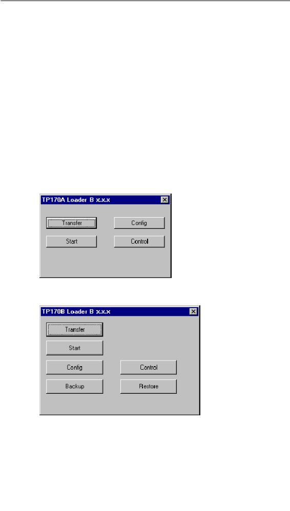
The options for Download mode can only be set when the operating unit is in its start-up phase. During the start-up phase, the Start menu appears briefly (TP170 A: Figure 3-1, TP170 B: Figure 3-2, OP170 B: Figure 3-3). Press the Config button to call in the Configuration menu (TP170 A: Figures 3-4, TP170 B and OP170 B: Figure 3-5).
Figure 3-1 TP170 A Start menu
Figure 3-2 TP170 B Start menu
3-6 |
TP170 A, TP 170 B, OP170 B Equipment Manual |
Release 07/00 |

Commissioning
Figure 3-3 OP170 B Start menu
Information on the buttons Backup and Restore (TP170 B and OP170 B) is available in Chapter 3.6.
Figure 3-4 TP170 A Configuration menu
Figure 3-5 TP170 B and OP170 B Configuration menu
TP170 A, TP 170 B, OP170 B Equipment Manual |
3-7 |
Release 07/00 |

Commissioning
Download mode settings
Setting the download options in the Configuration menu has the following effects:
SOption MPI Transfer Enable:
If this option is deactivated, the operating unit Download mode does not permit data transfer via an MPI connection. Activate the option to enable connection only via MPI or PROFIBUS-DP (SIMATIC S7).
SOption MPI Transfer Remote Control:
This option is only available if the option MPI Transfer Enable is activated.
When this option is active, the operating unit automatically switches from normal operation to Download mode in the case of an MPI transfer from the configuration computer.
SOption Serial Transfer Enable:
If this option is deactivated, the operating unit does not permit data transfer via a serial interface (refer to the note below).
SOption Serial Transfer Remote Control:
This option is only available if the option Serial Transfer Enable is activated.
When this option is active, the operating unit automatically switches from normal operation to Download mode in the case of a serial transfer from the configuration computer.
Press the OK button to confirm the settings currently defined for the download options. The Configuration menu is closed and the Start menu appears.
Press the Cancel button to close the Configuration menu and access the Start menu. Any modifications made to the settings are rejected.
The group “MPI Transfer” displays both bus parameters “MPI address” and “Baud Rate”. These parameters are valid for the project currently loaded on the operating unit.
Caution
!When the option Remote Control is active, ensure that the operating unit is not inadvertently switched to download mode from the configuration computer when in normal operation.
Note
If the options MPI Transfer Enable and Serial Transfer Enable are deactivated, it is not possible to download a project from the configuration computer to the operating unit.
3-8 |
TP170 A, TP 170 B, OP170 B Equipment Manual |
Release 07/00 |
Loading...