Siemens TC35i User Manual
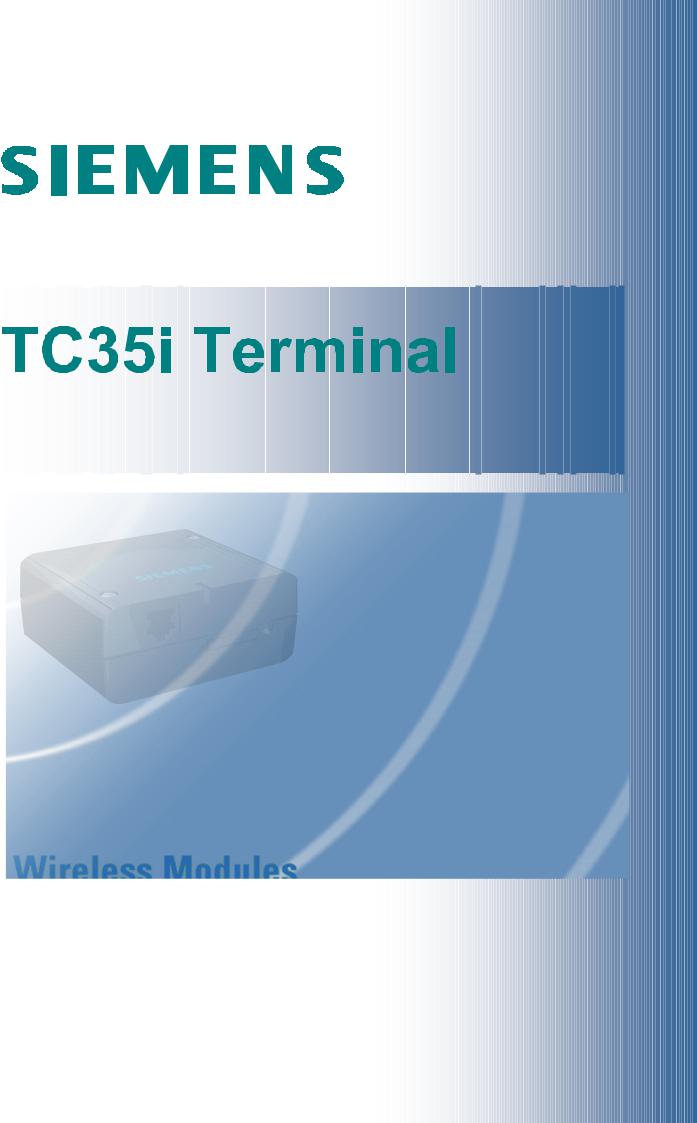
Siemens Cellular Engine
Hardware
Interface
Description
Version: 01.05
DocID: TC35i T HD v01.05
TC35i Terminal Hardware Interface Description
Confidential / Released
Document Name: |
TC35i Terminal Hardware Interface Description |
Version: |
01.05 |
Date: |
10.07.2003 |
DocId: |
TC35i_T_HD_v01.05 |
Status: |
Confidential / Released |
General notes
Product is deemed accepted by Recipient and is provided without interface to Recipient´s products. The Product constitutes pre-release version and code and may be changed substantially before commercial release. The Product is provided on an “as is” basis only and may contain deficiencies or inadequacies. The Product is provided without warranty of any kind, express or implied. To the maximum extent permitted by applicable law, Siemens further disclaims all warranties, including without limitation any implied warranties of merchantability, fitness for a particular purpose and noninfringement of third-party rights. The entire risk arising out of the use or performance of the Product and documentation remains with Recipient. This Product is not intended for use in life support appliances, devices or systems where a malfunction of the product can reasonably be expected to result in personal injury. Applications incorporating the described product must be designed to be in accordance with the technical specifications provided in these guidelines. Failure to comply with any of the required procedures can result in malfunctions or serious discrepancies in results. Furthermore, all safety instructions regarding the use of mobile technical systems, including GSM products, which also apply to cellular phones must be followed. Siemens AG customers using or selling this product for use in any applications do so at their own risk and agree to fully indemnify Siemens for any damages resulting from illegal use or resale .To the maximum extent permitted by applicable law, in no event shall Siemens or its suppliers be liable for any consequential, incidental, direct, indirect, punitive or other damages whatsoever (including, without limitation, damages for loss of business profits, business interruption, loss of business information or data, or other pecuniary loss) arising out the use of or inability to use the Product, even if Siemens has been advised of the possibility of such damages. Subject to change without notice at any time.
Copyright notice
Transmittal, reproduction, dissemination and/or editing of this document as well as utilization of its contents and communication thereof to others without express authorization are prohibited. Offenders will be held liable for payment of damages. All rights created by patent grant or registration of a utility model or design patent are reserved.
Copyright © Siemens AG 2003
Trademark notice
MS Windows is a registered trademark of Microsoft Corporation.
TC35i_T_HD_v01.05 |
Page 2/37 |
10.07.2003 |

TC35i Terminal Hardware Interface Description
Confidential / Released
Contents
0 |
Document history....................................................................................................... |
5 |
||
1 |
Introduction ................................................................................................................ |
6 |
||
|
1.1 |
References ......................................................................................................... |
6 |
|
|
1.2 |
Standards ........................................................................................................... |
7 |
|
|
1.3 |
Safety precautions .............................................................................................. |
8 |
|
|
1.4 |
Terms and abbreviations.................................................................................... |
10 |
|
2 |
Key features of TC35i Terminal................................................................................ |
12 |
||
3 |
Interface description................................................................................................. |
13 |
||
|
3.1 |
Overview............................................................................................................ |
13 |
|
|
3.2 |
Block diagram of a GSM application .................................................................. |
14 |
|
|
3.3 |
The TC35i GSM engine ..................................................................................... |
15 |
|
|
3.4 |
Operating modes ............................................................................................... |
16 |
|
|
3.5 |
Terminal circuit................................................................................................... |
17 |
|
|
|
3.5.1 Power supply and On/Off control ............................................................ |
18 |
|
|
|
3.5.1.1 Maximum number of turn/on & turn/off cycles ...................................... |
19 |
|
|
|
3.5.2 |
RTC ........................................................................................................ |
20 |
|
3.6 |
Upgrading TC35i Terminal firmware .................................................................. |
20 |
|
|
|
3.6.1 |
RS - 232 interface ..................................................................................... |
20 |
|
|
3.6.2 |
Audio interface ........................................................................................ |
22 |
|
|
3.6.3 |
Radio interface ....................................................................................... |
25 |
|
|
3.6.4 |
SIM interface .......................................................................................... |
26 |
|
|
3.6.5 |
Status LED ............................................................................................. |
26 |
4 |
Mechanical characteristics and mounting advice .................................................. |
27 |
||
|
4.1 |
Attaching the terminal ........................................................................................ |
28 |
|
5 |
Electrical and environmental characteristics.......................................................... |
29 |
||
6 |
Full type approval...................................................................................................... |
35 |
||
|
6.1 |
Restrictions ........................................................................................................ |
36 |
|
|
6.2 |
CE Conformity.................................................................................................... |
36 |
|
|
6.3 |
EMC |
................................................................................................................... |
36 |
7 |
List of parts ..........................................................and recommended accessories |
37 |
||
TC35i_T_HD_v01.05 |
Page 3/37 |
10.07.2003 |

TC35i Terminal Hardware Interface Description |
|
Confidential / Released |
|
Figures |
|
Figure 1: Block diagram of a TC35i Terminal application (example)..................................... |
14 |
Figure 2: TC35i GSM engine................................................................................................ |
15 |
Figure 3: TC35i Terminal circuit block diagram .................................................................... |
17 |
Figure 4: Female 6-pole Western plug for power supply, ignition, power down .................... |
18 |
Figure 5: Pin assignment RS-232 (D-Sub 9-pole female)..................................................... |
20 |
Figure 6: Audio Western plug (4-pole female)...................................................................... |
22 |
Figure 7: Audio block diagram.............................................................................................. |
22 |
Figure 8: Antenna connector circuit on TC35i module.......................................................... |
25 |
Figure 9: Recommended antenna connector........................................................................ |
25 |
Figure 10: Design drawing ................................................................................................... |
27 |
Figure 11: Recommended screws........................................................................................ |
28 |
Figure 12: Attaching TC35i Terminal onto a top-hat rail ....................................................... |
28 |
Figure 13: Reference equipment for approval ...................................................................... |
35 |
Tables |
|
Table 1: Terms and abbreviations ........................................................................................ |
10 |
Table 2: Key features ........................................................................................................... |
12 |
Table 3: Overview of operating modes ................................................................................. |
16 |
Table 4: Female 6-pole Western plug for power supply, ignition, power down ..................... |
19 |
Table 5: 9-pole D-Sub (female) RS-232 ............................................................................... |
21 |
Table 6: Audio modes .......................................................................................................... |
23 |
Table 7: Coding of the green status LED ............................................................................. |
26 |
Table 8: Mechanical characteristics...................................................................................... |
27 |
Table 9: Absolute maximum ratings ..................................................................................... |
29 |
Table 10: Operating conditions............................................................................................. |
29 |
Table 11: Characteristics power supply................................................................................ |
30 |
Table 12: Characteristics (requirements) On/Off control lines .............................................. |
31 |
Table 13: Characteristics (requirements) RS-232 interface .................................................. |
31 |
Table 14: Characteristics (requirements) audio interface ..................................................... |
32 |
Table 15: AT adjustable parameters .................................................................................... |
33 |
Table 16: Air interface .......................................................................................................... |
34 |
TC35i_T_HD_v01.05 |
Page 4/37 |
10.07.2003 |

TC35i Terminal Hardware Interface Description
Confidential / Released
0 Document history
Preceding document: "TC35i Terminal Hardware Interface Description" Version 00.40 New document: "TC35i Terminal Hardware Interface Description" Version 01.05
Chapter |
Page |
What is new |
0 |
6 |
Added Application Note 24: Application Developers’ Guide |
|
|
|
1.2, 7 |
6, 37 |
TC35i Terminal now fully type approved and labeled with CE mark |
|
|
|
TC35i_T_HD_v01.05 |
Page 5/37 |
10.07.2003 |

TC35i Terminal Hardware Interface Description
Confidential / Released
1 Introduction
This document describes the hardware of the Siemens TC35i Terminal. The information are intended for users, developers or manufacturers who design and build cellular applications beyond the standard setup. The scope of this document includes interface specifications, electrical issues and mechanical characteristics of TC35i Terminal. It specifies standards pertaining to wireless applications and outlines requirements that must be adhered to for successful product design. The TC35i Terminal is a compact GSM modem for the transfer of data, voice, SMS and faxes in GSM networks. Industrial standard interfaces and an integrated SIM card reader allow using TC35i Terminal easily as a dual band GSM terminal. The functionality of the Terminal corresponds to the features of the TC35i module.
1.1 References
[1]TC35i AT Command Set for TC35i and TC35i Terminal, Version 01.05
[2]Release Note, Version 01.05
[3]Application Note 16: Upgrading TC35i Terminal firmware
[4]Application Note 02: Audio Interface Design
[5]Application Note 24: Application Developers’ Guide
[6]Remote Sat User’s Guide
[7]Multiplexer User’s Guide
[8]Multiplexer Driver Developer’s Guide for Windows 2000 and Windows XP
[9]Multiplexer Driver Installation Guide for Windows 2000 and Windows XP
Prior to using the GSM engine, be sure to carefully read and understand the latest product information provided in the Release Notes.
To visit the Siemens Website you can use the following link:
http://www.siemens.com/wm
TC35i_T_HD_v01.05 |
Page 6/37 |
10.07.2003 |

TC35i Terminal Hardware Interface Description
Confidential / Released
1.2 Standards
TC35i Terminal has been approved to comply with the directives and standards listed below and is labeled with the CE conformity mark.
Directives
99/05/EC |
Directive of the European Parliament and of the council of 9 March |
|
1999 on radio equipment and telecommunications terminal |
|
equipment and the mutual recognition of their conformity, in short |
|
referred to as R&TTE Directive 1999/5/EC |
89/336/EC |
Directive on electromagnetic compatibility |
73/23/EC |
Directive on electrical equipment designed for use within certain |
|
voltage limits (Low Voltage Directive) |
95/54/EC |
Automotive EMC Directive |
Standards of type approval
ETS 300 607-1 |
Digital cellular telecommunications system (Phase 2); |
|
Mobile Station (MS) conformance specification; |
|
(equal GSM 11.10-1=>equal 3GPP TS 51.010-1) |
EN 301 511 |
V7.0.1 (2000-12) Candidate Harmonized European Standard |
|
(Telecommunications series) Global System for Mobile |
|
communications (GSM); Harmonized standard for mobile stations in |
|
the GSM 900 and DCS 1800 bands covering essential requirements |
|
under article 3.2 of the R&TTE directive (1999/5/EC) (GSM 13.11 |
|
version 7.0.1 Release 1998) |
EN 301 489-7 |
V1.1.1 (2000-09) Candidate Harmonized European Standard |
|
(Telecommunications series) Electro Magnetic Compatibility and |
|
Radio spectrum Matters (ERM); Electro Magnetic Compatibility |
|
(EMC) standard for radio equipment and services; Part 7: Specific |
|
conditions for mobile and portable radio and ancillary equipment of |
|
digital cellular radio telecommunications systems (GSM and DCS) |
EN 60 950 |
Safety of information technology equipment (2000) |
Requirements of quality
IEC 60068 |
Environmental testing |
DIN EN 60529 |
IP codes |
TC35i_T_HD_v01.05 |
Page 7/37 |
10.07.2003 |
TC35i Terminal Hardware Interface Description
Confidential / Released
1.3 Safety precautions
The following safety precautions must be observed during all phases of the operation, usage, service or repair of any cellular terminal or mobile incorporating TC35i Terminal. Manufacturers of the cellular terminal are advised to convey the following safety information to users and operating personnel and to incorporate these guidelines into all manuals supplied with the product. Failure to comply with these precautions violates safety standards of design, manufacture and intended use of the product. Siemens AG assumes no liability for customer failure to comply with these precautions.
When in a hospital or other health care facility, observe the restrictions on the use of mobiles. Switch the cellular terminal or mobile off, if instructed to do so by the guidelines posted in sensitive areas. Medical equipment may be sensitive to RF energy.
The operation of cardiac pacemakers, other implanted medical equipment and hearing aids can be affected by interference from cellular terminals or mobiles placed close to the device. If in doubt about potential danger, contact the physician or the manufacturer of the device to verify that the equipment is properly shielded. Pacemaker patients are advised to keep their hand-held mobile away from the pacemaker, while it is on.
Switch off the cellular terminal or mobile before boarding an aircraft. Make sure it cannot be switched on inadvertently. The operation of wireless appliances in an aircraft is forbidden to prevent interference with communications systems. Failure to observe these instructions may lead to the suspension or denial of cellular services to the offender, legal action, or both.
Do not operate the cellular terminal or mobile in the presence of flammable gases or fumes. Switch off the cellular terminal when you are near petrol stations, fuel depots, chemical plants or where blasting operations are in progress. Operation of any electrical equipment in potentially explosive atmospheres can constitute a safety hazard.
Your cellular terminal or mobile receives and transmits radio frequency energy while switched on. Remember that interference can occur if it is used close to TV sets, radios, computers or inadequately shielded equipment. Follow any special regulations and always switch off the cellular terminal or mobile wherever forbidden, or when you suspect that it may cause interference or danger.
Road safety comes first! Do not use a hand-held cellular terminal or mobile when driving a vehicle, unless it is securely mounted in a holder for handsfree operation. Before making a call with a hand-held terminal or mobile, park the vehicle.
Handsfree devices must be installed by qualified personnel. Faulty installation or operation can constitute a safety hazard.
TC35i_T_HD_v01.05 |
Page 8/37 |
10.07.2003 |
TC35i Terminal Hardware Interface Description
Confidential / Released
|
|
|
IMPORTANT! |
|
SOS |
||||
|
||||
|
Cellular terminals or mobiles operate using radio signals and cellular |
|||
|
|
|
networks cannot be guaranteed to connect in all conditions. Therefore, you |
|
|
|
|
||
|
|
|
should never rely solely upon any wireless device for essential |
|
|
|
|
communications, for example emergency calls. |
|
Remember, in order to make or receive calls, the cellular terminal or mobile must be switched on and in a service area with adequate cellular signal strength.
Some networks do not allow for emergency calls if certain network services or phone features are in use (e.g. lock functions, fixed dialling etc.). You may need to deactivate those features before you can make an emergency call.
Some networks require that a valid SIM card be properly inserted in the cellular terminal or mobile.
If a power supply unit is used to supply the device, it must meet the demands placed on SELV circuits in accordance with EN60950. The maximum permissible connection length between the device and the supply source should not exceed 3m.
According to the guidelines for human exposure to radio frequency energy, an antenna connected to the FME jack of the device should be placed at least 20cm away from human bodies.
TC35i_T_HD_v01.05 |
Page 9/37 |
10.07.2003 |

TC35i Terminal Hardware Interface Description
Confidential / Released
1.4 Terms and abbreviations
Table 1: Terms and abbreviations
Abbreviation |
Description |
ADC |
Analog-to-Digital Converter |
|
|
ARP |
Antenna Reference Point |
|
|
ASIC |
Application Specific Integrated Circuit |
|
|
ATC |
AT Cellular |
|
|
BTS |
Base Transceiver Station |
|
|
CB |
Cell Broadcast |
|
|
CODEC |
Coder-Decoder |
|
|
CPU |
Central Processing Unit |
|
|
DCE |
Data Circuit terminating Equipment |
|
|
DSB |
Development Support Box |
|
|
DSP |
Digital Signal Processor |
|
|
DSR |
Data Set Ready |
|
|
DTR |
Data Terminal Ready |
|
|
EFR |
Enhanced Full Rate |
|
|
EGSM |
Enhanced GSM |
|
|
EMC |
Electromagnetic Compatibility |
|
|
ESD |
Electrostatic Discharge |
|
|
ETS |
European Telecommunication Standard |
|
|
FDMA |
Frequency Division Multiple Access |
|
|
FR |
Full rate |
|
|
G.C.F. |
GSM Conformity Forum |
|
|
GSM |
Global Standard for Mobile Communication |
|
|
HF |
Hands-free |
|
|
HR |
Half rate |
|
|
HW |
Hardware |
|
|
IC |
Integrated Circuit |
|
|
IF |
Intermediate Frequency |
|
|
IMEI |
International Mobile Equipment Identifier |
|
|
I/O |
Input/ Output |
|
|
IGT |
Ignition |
|
|
ISO |
International Standards Organization |
|
|
ITU |
International Telecommunications Union |
|
|
kbps |
kbits per second |
|
|
TC35i_T_HD_v01.05 |
Page 10/37 |
10.07.2003 |

TC35i Terminal Hardware Interface Description
Confidential / Released
Abbreviation |
Description |
Li-Ion |
Lithium-Ion |
|
|
LVD |
Low voltage Directive |
|
|
Mbps |
Mbits per second |
|
|
MMI |
Machine Machine Interface |
|
|
MO |
Mobile Originated |
|
|
MS |
Mobile Station |
|
|
MT |
Mobile Terminated |
|
|
NC |
Not Connected |
|
|
NTC |
Negative Temperature Coefficient |
|
|
PA |
Power Amplifier |
|
|
PCB |
Printed Circuit Board |
|
|
PCM |
Pulse Code Modulation |
|
|
PCS |
Personal Communication System |
|
|
PD |
Power Down |
|
|
PDU |
Protocol Data Unit |
|
|
R&TTE |
Radio and Telecommunication Terminal Equipment |
|
|
RAM |
Random Access Memory |
|
|
RF |
Radio frequency |
|
|
RI |
Ring Indication |
|
|
ROM |
Read Only Memory |
|
|
RX |
Receive direction |
|
|
SIM |
Subscriber Identification Module |
|
|
SMS |
Short Message Service |
|
|
SRAM |
Static Random Access Memory |
|
|
SW |
Software |
|
|
TBD |
To Be Defined |
|
|
TDD |
Time Division Duplex |
|
|
TDMA |
Time Division Multiple Access |
|
|
TX |
Transmit direction |
|
|
UART |
Universal Asynchronous Receiver and Transmitter |
|
|
VAD |
Voice Activity Detection |
|
|
ZIF |
Zero Insertion Force |
|
|
TC35i_T_HD_v01.05 |
Page 11/37 |
10.07.2003 |

TC35i Terminal Hardware Interface Description
Confidential / Released
2 Key features of TC35i Terminal
Table 2: Key features |
|
|
|
Feature |
Implementation |
Transmission |
Voice, Data, SMS, Fax |
|
|
Power supply |
Single supply voltage 8V to 30V |
|
|
GSM class |
Small MS |
|
|
Frequency bands |
Dual Band E-GSM 900 and GSM 1800 |
|
Compliant to GSM Phase 2/2+ |
|
|
Transmit power |
Class 4 (2W) for EGSM900 |
|
Class 1 (1W) for GSM1800 |
|
|
SIM card reader |
Internal |
|
|
External antenna |
Connected via antenna FME connector |
|
|
Speech codec |
Triple rate codec: |
|
Half Rate (ETS 06.20) |
|
Full Rate (ETS 06.10) |
|
Enhanced Full Rate (ETS 06.50 / 06.60 / 06.80) |
SMS |
MT, MO, CB, Text and PDU mode |
|
|
DATA |
2.4, 4.8, 9.6, 14.4 kbps, non-transparent, V.110 |
|
Unstructured Supplementary Services Data (USSD) support |
|
|
FAX |
Group 3: Class 1, Class 2 |
|
|
Audio interface |
Analog (Microphone, Earpiece) |
|
|
Serial interface |
2.65V level, bi-directional bus for AT commands and data |
|
Multiplex ability according to GSM 07.10 Multiplexer protocol |
|
Baud rates from 300bps to 115.200bps |
|
Autobauding supports: 1.200, 2.400, 4.800, 9.600, 19.200, |
|
38.400, 57.600 and 115.200bps |
|
|
Supported SIM card |
3V |
|
|
Phonebook management |
Supported phonebook types: SM, FD, LD, MC, RC, ON, ME |
|
|
Reset of TC35i Terminal |
Reset via AT command or Power Down Signal |
|
|
Firmware upgrade |
Upgradable via serial interface or SIM interface. |
|
|
Real time clock |
Implemented (clock frequency 32.768kHz) |
|
|
Environmental |
Temperature: |
|
Normal operation: -20°C to +55°C to +65°C |
|
Humidity: max. 80 % relative humidity |
|
|
Size |
65x74x33 mm (approx.) |
|
|
Weight |
130g |
|
|
TC35i_T_HD_v01.05 |
Page 12/37 |
10.07.2003 |
 Loading...