


ENGLISH
MODEL
HT-SB602
SOUND BAR HOME THEATRE SYSTEM
OPERATION MANUAL
Thank you for purchasing this SHARP product. To obtain the best performance from this product, please read this manual carefully. It will guide you in operating your SHARP product.
HT-SB602 Sound Bar Home Theatre system consisting of HT-SB602 (sound bar system) and CP-SW602 (active subwoofer system).
Note:
This product is recommended for 60" or larger fl at panel TV (LED, LCD and Plasma).
TINSEA467AWZZ |
|
14F R AS 1 |
|
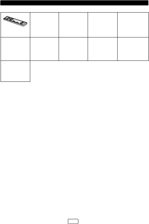
Accessories
The following accessories are included.
Remote Control |
Subwoofer Stand x 2 |
Audio Cable x 1 |
HDMI Cable x 1 |
IR Transmitter x 1 |
|
(RRMCGA331AWSA) |
|||||
|
|
|
|
||
Wall Mount Angle x 2 |
Pattern Paper |
NFC tag x 1 |
Velcro tape (hook type) x 1 |
Velcro tape (loop type) x 2 |
|
“AAA” size battery (UM-4, |
|
|
|
|
|
R03, HP-16 or similar) x 2 |
|
|
|
|
Special Notes
For DTS patents, see http://patents.dts.com. Manufactured under license from DTS Licensing Limited. DTS, the Symbol, & DTS and the Symbol together are registered trademarks, and DTS Digital Surround is a trademark of DTS, Inc. © DTS, Inc. All Rights Reserved.
Manufactured under license from Dolby Laboratories. Dolby and the double-D symbol are trademarks of Dolby Laboratories.
HDMI, the HDMI Logo, and High-Defi nition Multimedia Interface are trademarks or registered trademarks of HDMI Licensing LLC in the United States and other countries.
Warning:
When the ON/STANDBY button is set at STANDBY position, mains voltage is still present inside the unit. When the ON/STANDBY button is set at STANDBY position, the unit may be brought into operation by the timer mode or remote control.
This unit contains no user serviceable parts. Never remove covers unless qualifi ed to do so. This unit contains dangerous voltages, always remove mains plug from the socket before any service operation and when not in use for a long period.
To prevent fi re or shock hazard, do not expose this appliance to dripping or splashing. No objects fi lled with liquids, such as vases, shall be placed on the apparatus.
The Bluetooth® word mark and logos are registered trademarks owned by Bluetooth SIG, Inc. and any use of such marks by SHARP is under license. Other trademarks and trade names are those of their respective owners.
The N Mark is a trademark or registered trademark of NFC Forum, Inc. in the United States and in other countries.
E-1
Precautions
General
Keep your equipment at least 10 cm of free space along the sides, top and back for proper ventilation.
10 cm
10 cm |
|
|
10 cm |
|||||||||||
|
|
|
|
|
|
|
|
|
|
|
|
|
|
|
|
|
|
|
|
|
|
|
|
|
|
|
|
|
|
|
|
|
|
|
|
|
|
|
|
|
|
|
|
|
10 cm |
10 cm |
10 cm
10 cm
Use the unit on a fi rm, level surface free from vibration.
Keep the unit away from direct sunlight, strong magnetic fi elds, excessive dust, humidity and electronic/electrical equipment (home computers, facsimiles, etc.) which generate electrical noise.
Do not place anything on top of the unit.
Do not expose the unit to moisture, to temperatures higher than 60°C (140°F) or to extremely low temperatures.
If the unit does not work properly, unplug and plug it in again. Than turn on the unit.
In case of an electrical storm, unplug the unit for safety.
Hold the AC power plug by the head when removing it from the wall socket, as pulling the lead can damage internal wires.
The AC power plug is used as a disconnect device and shall always remain readily operable.
Do not remove the outer cover, as this may result in electric shock. Refer internal service to your local SHARP service facility.
The ventilation should not be impeded by covering the ventilation openings with items, such as newspapers, tablecloths, curtains, etc.
No naked fl ame sources, such as lighted candles, should be placed on the apparatus.
Attention should be drawn to the environmental aspects of battery disposal.
This unit should only be used within the range of 5°C - 35°C (41°F - 95°F).
SHARP is not responsible for damage due to improper use. Refer all servicing to a SHARP authorised service centre.
Warnings:
The voltage used must be the same as that specifi ed on this unit. Using a higher voltage is dangerous and may result in a fi re or other type of accident causing damage. SHARP will not be held responsible for any damage resulting from such usage.
In case of repairing, please bring the entire system set to the service centre.
Volume control
The sound level at a given volume setting depends on speaker effi ciency, location and various other factors. It is advisable to avoid exposure to high volume levels, which occurs whilst turning the unit on with the volume control setting up high, or whilst continually listening at high volumes.
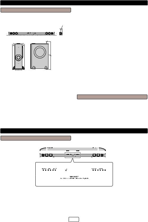
Controls and indicators
Sound Bar Front Panel
1 |
|
|
|
|
|
|
2 |
|
|
|
|
|
|||||||||||
|
|
|
|
|
|
|
|
|
|
|
|
|
|
|
|
|
|
|
|
|
|
|
|
|
|
|
|
|
|
|
|
|
|
|
|
|
|
|
|
|
|
|
|
|
|
|
|
|
|
|
|
|
|
|
|
|
|
|
|
|
|
|
|
|
|
|
|
|
|
|
|
|
|
|
|
|
|
|
|
|
|
|
|
|
|
|
|
|
|
|
|
|
|
|
|
|
|
|
|
|
|
|
|
|
|
|
|
|
|
|
|
|
|
|
|
|
|
|
|
|
|
|
|
|
|
|
|
|
|
|
|
|
|
|
|
|
|
|
|
|
|
|
|
|
|
|
|
|
|
|
|
|
|
|
|
|
|
|
|
|
|
|
|
|
|
|
|
|
|
|
|
|
|
|
|
|
|
|
|
|
|
|
|
|
|
|
|
|
|
|
|
|
|
|
|
|
|
|
|
|
|
|
|
|
|
|
|
|
|
|
|
|
|
|
|
|
|
|
|
|
|
|
|
|
|
|
|
|
|
|
|
|
|
|
|
|
|
|
|
|
|
|
|
|
|
|
|
|
|
|
|
|
|
|
|
|
|
|
|
|
|
|
|
|
3 |
4 |
5 |
6 |
|
7 |
8 |
9 |
1. |
Left Channel Speakers |
|
|
|
7. |
Sound Mode Button |
||
2. |
Right Channel Speakers |
|
|
|
8. |
Volume Down Button |
||
3. |
On/Standby Button |
|
|
|
9. |
Volume Up Button |
||
4.INPUT Button
5.Pairing Button
6.Remote Sensor
E-2
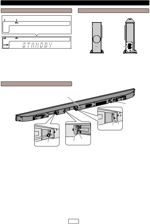
Controls and indicators (continued)
Display |
Subwoofer |
1 2
 DIGITAL


 3
3
DIGITAL |
1.Dolby Digital Indicator
2.DTS Indicator
3.Muting Indicator
Sound Bar Rear Panel
1
FRONT VIEW
1 

2
 4 3
4 3 

REAR VIEW
5 |
6 |
1.NFC detection area
2.Power/Pairing Indicator
3.Bass Reflect Duct
4.Woofer
5.SW LINK (Subwoofer Link) button
6.AC Power Lead

 7
7
5 6
4
2 |
3 |
|
1.IR OUT Terminal
2.HDMI OUT (TV ARC) Socket
3.HDMI IN 1 Socket
4.HDMI IN 2 Socket
5.Optical IN Socket
6.Audio IN Terminal
7.AC Power Lead
E-3

Controls and indicators (continued)
1 |
|
|
2 |
20 |
|
3 |
21 |
|
22 |
||
4 |
||
5 |
23 |
|
6 |
24 |
|
7 |
||
25 |
||
|
||
8 |
26 |
|
9 |
27 |
|
10 |
28 |
|
11 |
||
12 |
29 |
|
13 |
30 |
|
14 |
|
|
15 |
31 |
|
16 |
32 |
|
33 |
||
17 |
34 |
|
18 |
35 |
|
19 |
|
Remote Control
1.Remote Control Transmitter
2.ON/STANDBY Button
3.HDMI 2 Button
4.HDMI 1 Button
5.OPTICAL Button
6.MUSIC (Sound Mode) Button
7.CINEMA (Sound Mode) Button
8.SPORT (Sound Mode) Button
9.BYPASS Button
10.3D AUDIO Button
11.Bluetooth Skip Down Button
12.Bluetooth Pairing Button
13.Volume Up Button
14.AV SYNC Up Button
15.BASS Button
16.Volume Down Button
17.MUTE Button
18.APC Button
19.TV Operation Button
20.

 (
( ) Speaker Select Button
21.ARC Button
22. (Bluetooth) Button
23.AUDIO IN Button
24.GAME (Sound Mode) Button
25.NEWS (Sound Mode) Button
26.NIGHT (Sound Mode) Button
27.DIMMER Button
28.Bluetooth Play/Pause Button
29.Bluetooth Skip Up Button
30.SW (Subwoofer) Level Up Button
31.TREBLE Button
32.AV SYNC Down Button
33.SW (Subwoofer) Level Down Button
34.SW (Subwoofer) LINK Button
35.ECO MODE Button
TV Operation Buttons (Only SHARP TV):
On/Standby |
Sets the |
Input Select |
Press the |
Button |
TV power |
Button (TV) |
button to |
|
to “ON” or |
|
switch the |
|
“STANDBY”. |
|
input source. |
Channel Up |
Switch up/ |
Volume Up |
Turn up/ |
and Down |
down the TV |
and Down |
down the TV |
Buttons |
channels. |
Buttons |
volume. |
|
|
|
|
AV Mode |
Press the |
MUTE Button |
Press the |
Button |
button to |
|
button to |
|
switch AV |
|
mute the TV |
|
mode. |
|
volume. |
Note:
Some models of SHARP TV may not be operable.
E-4
Sound bar preparation
To mount the sound bar on the wall
Caution:
Be very careful to prevent the sound bar 3.7 kg from falling when mounting on the wall.
Before mounting, check the wall strength. (Do not put on the veneer plaster or whitewashed wall. The sound bar may fall.) If unsure, consult a qualified service technician.
Mounting screws are not supplied. Use appropriate ones.
Check all wall mount angle screws for looseness.
Select a good location. If not, accidents may occur or the sound bar may get damaged.
SHARP is not responsible for accidents resulting from improper installation.
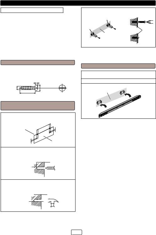
Driving screws
SHARP designed the sound bar so you may hang them on the wall. Use proper screws (not supplied). See below for size and type.
3.2 mm
5 mm
9 mm
Min. 22 mm
Fixing wall mount angle (Horizontal position)
1Fix the pattern paper to the wall in horizontal position as below.
926 mm |
44 mm |
|
|
Wall surface 44 mm |
29 mm |
|
|
29 mm |
Pattern paper |
|
2Make a hole on the wall following the screw point marks on the pattern paper by using a
drill.
32 mm
8-9 mm 

Wall surface
3Fix a wall mount plug (not supplied) into the hole using a hammer, until it is flush with the
wall surface.
32 mm
8-9 mm 


Wall surface
4Screw the wall mount angle to the wall as shown in the illustration. (Total screw is 8 pieces)
Wall mount angle |
|
|
Wall mount |
|
|
angle |
Wall |
Wall |
(screws x 4) |
surface |
mount |
Wall surface |
|
angle |
|
|
|
(screws x 4) |
|
|
Wall surface |
|
|
Note:
Make sure all screws are fully tightened. (screws are not supplied)
Installing the sound bar
1Align the wall mount slot at the sound bar to the wall mount angle.
2Slot the sound bar into the wall mount angle.
3Fix them securely.
Wall surface
E-5

Falling prevention
Safety wires (not supplied) are useful to prevent the sound bar from falling off.
2 persons are required to perform this procedure.
When mounting on the wall
1Loop the safety wires (not supplied) into each hole of the wall mount angle as shown.
Wall surface
2Loop the safety wires from wall mount angle into each hole of sound bar as shown.
3 Align and fix the sound bar to wall mount angle.
Wall surface
4 Tie the safety wires tightly.
 Wall surface
Wall surface
When placing on the shelf/table
Loop the safety wires (not supplied) into each hole as shown and tie the safety wires to the LCD TV stand.
E-6
 Loading...