


SPLIT TYPE
ROOM AIR CONDITIONER
INSTALLATION AND OPERATION MANUAL
CONDIZIONATORE D'ARIA
DA CAMERA TIPO SPLIT
MANUALE PER L'INSTALLAZIONE E IL FUNZIONAMENTO
AR CONDICIONADO DE SALA DE DUAS UNIDADES
MANUAL DE OPERAÇÃO E DE INSTALAÇÄO
PORTUGUÊS ITALIANO ENGLISH
INDOOR UNIT(PANEL)
GX-X18JR (AZ-18J) GX-X24JR (AZ-24J) GX-X36JR (AZ-24J)
OUTDOOR UNIT
GU-X18JR GU-X24JR GU-X36JR
|
|
|
|
|
|
|
|
|
|
|
|
|
|
|
|
GREE_cassette_cover.indd 1 |
|
08.10.22 3:55:36 PM |
|
|
|
||
|
|
||||||
|
|
|
|
|
|
|
|
Attention: Your product is marked with this symbol. It means that used electrical and electronic products should not be mixed with general household waste. There is a separate collection system for these products.
Pb
A. Information on Disposal for Users (private households)
1. In the European Union
Attention: If you want to dispose of this equipment, please do not use the ordinary dust bin!
Used electrical and electronic equipment must be treated separately and in accordance with legislation that requires proper treatment, recovery and recycling of used electrical and electronic equipment.
Following the implementation by member states, private households within the EU states may return their used electrical and electronic equipment to designated collection facilities free of charge*. In some countries* your local retailer may also take back your old product free of charge if you purchase a similar new one.
*) Please contact your local authority for further details.
If your used electrical or electronic equipment has batteries or accumulators, please dispose of these separately beforehand according to local requirements.
By disposing of this product correctly you will help ensure that the waste undergoes the necessary treatment, recovery and recycling and thus prevent potential negative effects on the environment and human health which could otherwise arise due to inappropriate waste handling.
2. In other Countries outside the EU
If you wish to discard this product, please contact your local authorities and ask for the correct method of disposal.
For Switzerland: Used electrical or electronic equipment can be returned free of charge to the dealer, even if you don’t purchase a new product. Further collection facilities are listed on the homepage of www.swico.ch or www.sens.ch.
B. Information on Disposal for Business Users.
1. In the European Union
If the product is used for business purposes and you want to discard it:
Please contact your SHARP dealer who will inform you about the take-back of the product. You might be charged for the costs arising from take-back and recycling. Small products (and small amounts) might be taken back by your local collection facilities.
For Spain: Please contact the established collection system or your local authority for take-back of your used products.
2. In other Countries outside the EU
If you wish to discard of this product, please contact your local authorities and ask for the correct method of disposal.
The battery supplied with this product contains traces of Lead.
For EU: The crossed-out wheeled bin implies that used batteries should not be put to the general household waste!
There is a separate collection system for used batteries, to allow proper treatment and recycling in accordance with legislation. Please contact your local authority for details on the collection and recycling schemes.
For Switzerland: The used battery is to be returned to the selling point.
For other non-EU countries: Please contact your local authority for correct method of disposal of the used battery.
EN
|
|
|
|
|
|
|
|
|
|
|
|
|
|
|
|
GREE_cassette_cover.indd 2 |
|
08.10.22 3:55:37 PM |
|
|
|
||
|
|
||||||
|
|
|
|
|
|
|
|
ENGLISH
CONTENTS
Operating Instructions
• IMPORTANT SAFETY INSTRUCTIONS. |
...................... E-2 |
• PART NAMES................................................................ |
E-3 |
• WIRE CONTROLLER OPERATION.............................. |
E-4 |
ON/OFF ..................................................................... |
E-5 |
Fan control ................................................................ |
E-5 |
Temperature setting................................................... |
E-5 |
Swing mode setting.................................................... |
E-6 |
Operation mode setting.............................................. |
E-6 |
TIMER setting............................................................ |
E-7 |
Display of outdoor temperature.................................. |
E-7 |
SAVE setting.............................................................. |
E-8 |
Memory function setting............................................. |
E-9 |
Failure display............................................................ |
E-9 |
• REMOTE CONTROLLER OPERATION ..................... |
E-10 |
Name and function.................................................... |
E-11 |
Loading batteries....................................................... |
E-11 |
Cool mode operation................................................ |
E-12 |
Heat mode operation................................................ |
E-12 |
Dry mode operation ................................................. |
E-13 |
Auto mode operation................................................ |
E-13 |
Fan mode operation................................................. |
E-14 |
Timer operation........................................................ |
E-14 |
Sleep mode operation.............................................. |
E-15 |
• OPTIMUM OPERATION.............................................. |
E-15 |
• TROUBLE SHOOTING................................................ |
E-16 |
• CARE AND MAINTENANCE....................................... |
E-17 |
Installation Instructions
• |
Installation notes.......................................................... |
E-20 |
• |
Indoor unit installation.................................................. |
E-20 |
• |
Electric wiring............................................................... |
E-25 |
• |
Installation of panel...................................................... |
E-26 |
• |
Outdoor unit installation............................................... |
E-28 |
• |
Position and method of installing wire controller.......... |
E-30 |
• |
Electrical installation.................................................... |
E-31 |
• |
Test run........................................................................ |
E-32 |
• |
Checks after installation............................................... |
E-33 |
• Appendix..................................................................... |
E-33 |
|
Please read this manual carefully before using the product. This manual should be kept in a safe place for handy reference.
E-
ENGLISH
|
|
|
|
|
|
|
|
|
|
|
|
|
|
|
|
GREE_cassette_eng.indd 1 |
|
08.10.28 11:42:39 AM |
|
|
|
||
|
|
||||||
|
|
|
|
|
|
|
|
|
|
|
|
|
|
|
|
|
|
|
|
|
|
|
|
|
|
|
|
|
|
|
|
|
|
|
|
|
|
|
|
|
|
|
|
|
|
|
|
|
|
|
|
|
|
|
|
|
|
|
|
|
|
|
|
|
|
|
|
|
|
|
|
|
|
|
|
|
|
|
|
|
|
|
|
|
|
|
|
|
|
|
|
|
|
|
|
|
|
|
|
|
|
|
|
|
|
|
|
|
|
|
|
|
|
|
IMPORTANT SAFETY INSTRUCTIONS |
||||||||||||||||||||||
|
|
WARNINGS FOR USE |
|||||||||||||||||||||||
1 |
Do not pull or deform the power supply cord. Pulling and misuse of the power supply cord can result in |
||||||||||||||||||||||||
damage to the unit and cause electrical shock. |
|||||||||||||||||||||||||
2 |
Be careful not to expose your body directly to the outlet air for a long time. It may affect your physical |
||||||||||||||||||||||||
conditions. |
|||||||||||||||||||||||||
3 |
When using the air conditioner for infants, children, elderly, bedridden, or disabled people make sure the |
||||||||||||||||||||||||
room temperature is suitable for those in the room. |
|||||||||||||||||||||||||
4 |
Never insert objects into the unit. Inserting objects can result in injury due to the high speed rotation of |
||||||||||||||||||||||||
internal fans. |
|||||||||||||||||||||||||
5 |
Ground the air conditioner without fail. Do not connect the grounding wire to gas pipe, water pipe, lightning |
||||||||||||||||||||||||
rod or telephone grounding wire. Incomplete grounding may cause electric shock. |
|||||||||||||||||||||||||
6 |
If anything is abnormal with the air conditioner (ex. a burning smell), stop the operation immediately and |
||||||||||||||||||||||||
turn the circuit breaker OFF. |
|||||||||||||||||||||||||
7 |
The appliance shall be installed in accordance with national wiring regulations. Improper cable connection |
||||||||||||||||||||||||
can cause the power supply cord, plug and the electrical outlet to overheat and cause fire. |
|||||||||||||||||||||||||
8 |
If the supply cord is damaged, it must be replaced by the manufacturer or its service agent or a |
||||||||||||||||||||||||
similarly qualified person in order to avoid a hazard. Use only the manufacture-specified power cord for |
|||||||||||||||||||||||||
replacement.
CAUTIONS FOR USE
1
2
3
4
5
6
7
8
9
10
11
Open a window or door periodically to ventilate the room, especially when using gas appliances.
Insufficient ventilation may cause oxygen shortage.
Do not operate the buttons with wet hand. It may cause electric shock.
For safety, turn the circuit breaker off when not using the unit for an extended period of time.
Check the outdoor unit mounting rack periodically for wear and to make sure it is firmly in place.
Do not put anything on the outdoor unit nor step on it. The object or the person may fall down or drop, causing injury.
This unit is designed for residential use. Do not use for other applications such as in a kennel or greenhouse to raise animals or grow plants.
Do not place a vessel with water on the unit. If water penetrates into the unit, electrical insulations may deteriorate and cause electric shock.
Do not block the air inlets nor outlets of the unit. It may cause insufficient performance or troubles.
Be sure to stop the operation and turn the circuit breaker off before performing any maintenance or cleaning. A fan is rotating inside the unit and you may get injured.
Do not splash or pour water directly on the unit. Water can cause electrical shock or equipment damage.
This appliance is not intended for use by young children or infirm persons without supervision.
Young children should be supervised to ensure that they do not play with the appliance.
WARNINGS FOR INSTALLATION/REMOVAL/REPAIR
•Do not attempt to install/remove/repair the unit by yourself. Incorrect work will cause electric shock, water leak, fire etc. Consult your dealer or other qualified service personnel for the installation/removal/ repair of the unit.
CAUTIONS FOR LOCATION/INSTALLATION
•Make sure to connect the air conditioner to power supply of the rated voltage and frequency.
Use of a power supply with improper voltage and frequency can result in equipment damage and possible fire.
•Do not install the unit in a place where inflammable gas may leak. It may cause fire.
Install the unit in a place with minimal dust, fumes and moisture in the air.
•Arrange the drain hose to ensure smooth drainage. Insufficient drainage may cause wetting of the room, furniture etc.
•Make sure an earth leakage breaker or a circuit breaker is installed, depending on the installation location, to avoid electrical shock.
E-
|
|
|
|
|
|
|
|
|
|
|
|
|
|
|
|
GREE_cassette_eng.indd 2 |
|
08.10.28 11:42:39 AM |
|
|
|
||
|
|
||||||
|
|
|
|
|
|
|
|
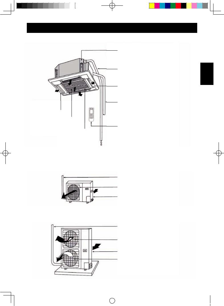
PART NAMES
Indoor unit
Drainage device (built-in)
Drainage pipe
Air flow flap (Air outlet)
Refrigerant piping Electric wire
Air outlet
Air filter
Remote controller
Air intake grille
Outdoor unit
GU-X18JR/GU-X24JR
Refrigerant pipe
Air outlet
Air intake
GU-X36JR
Refrigerant pipe
Air outlet
Air intake
Air outlet
E-
ENGLISH
|
|
|
|
|
|
|
|
|
|
|
|
|
|
|
|
GREE_cassette_eng.indd 3 |
|
08.10.28 11:42:40 AM |
|
|
|
||
|
|
||||||
|
|
|
|
|
|
|
|

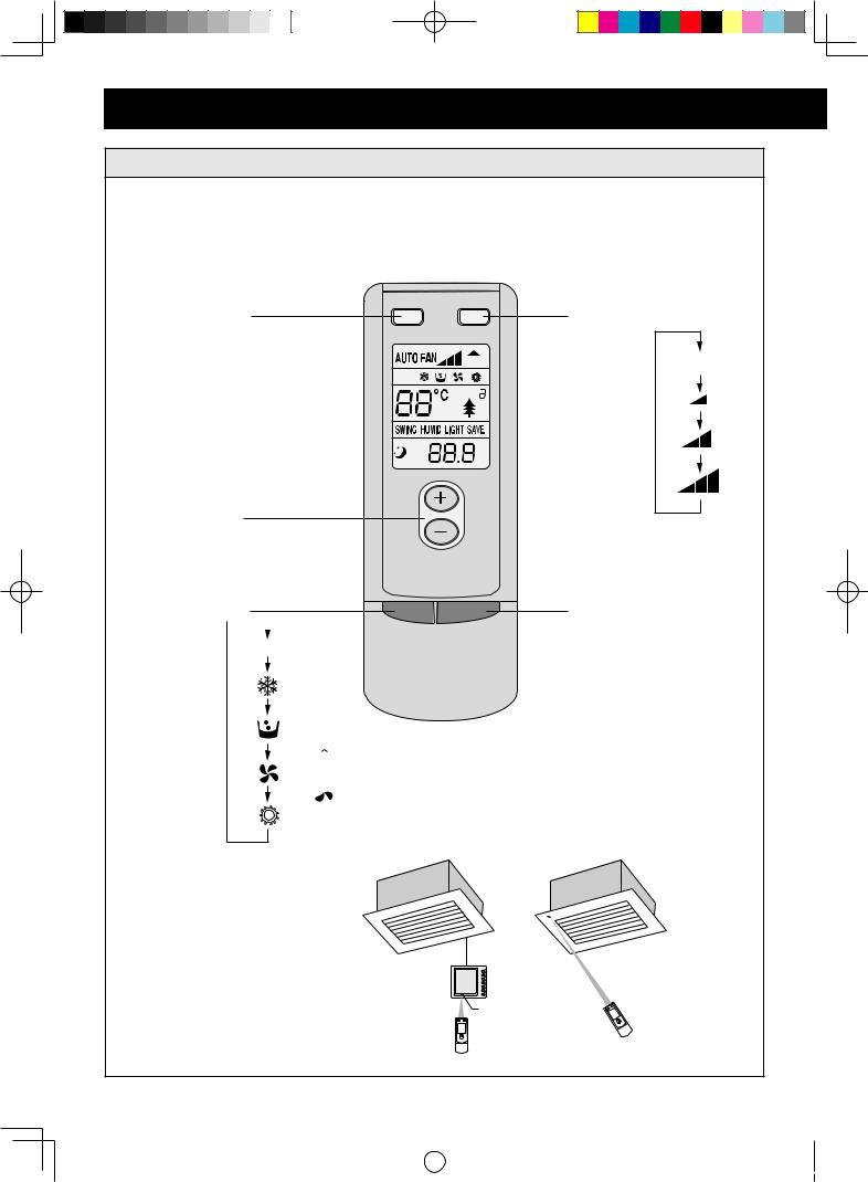
WIRE CONTROLLER OPERATION
WARNING:
Never install the wire controller in a place where there is water leakage. Avoid bumping, throwing, tossing or frequently opening the wire controller.
1
2
3
4
5
6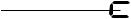


 7
7
8
1 |
Failure display |
2 |
TIMER display |
3 |
Fan speed display (Auto, High, Medium, Low) |
4 |
DEFROST display |
5 |
SAVE display |
6 |
Set temperature display |
7 |
Ambient temperature display |
8 |
Mode display (COOL, DRY, FAN, HEAT, AUTO) |
9 |
SWING display |
10 |
SLEEP display |
11 |
MODE button |
12 |
Temperature setting button (for temperature rise) |
13 |
Temperature setting button (for temperature drop) |
14 |
FAN button |
15 |
SWING button |
16 |
TIMER button |
17 |
ON/OFF button |
18 |
Receiver window |
E-
GREE_cassette_eng.indd 4
9
10
11
12
13
14
15
16
17
18
08.10.28 11:42:40 AM
ON/OFF
• Press the ON/OFF button, the unit will start.
• Press the ON/OFF button again, the unit will turn off.
ENGLISH
Fan control (The relevant contents are shown in the figure.)
• Press the FAN button to change fan speed.
 Low speed
  Medium speed
  Hight speed
  Auto
Auto
•In the DRY mode, the fan speed will be automatically set to Low.
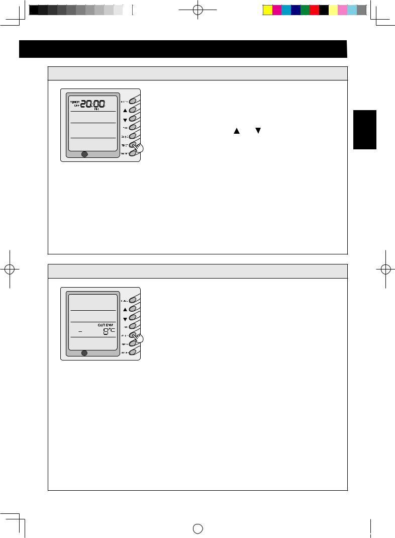
Temperature setting
•Press the temperature setting button
 : For temperature rise
 : For temperature drop
(Press the buttons once, the temperature setting will change by 1˚C.)
NOTE:
•Button Lock function
Press “ ” and ” ” at the same time for 5 seconds, the set temperature indicating area will display “EE” and all keys’ response will be shut off.
To cancel the button lock function, press the “ ” and ”  ” simultaneously for 5 seconds.
•The set temperature range
HEAT/COOL/DRY: 16˚C~30˚C
FAN / AUTO: The temperature cannot be set up
E-
|
|
|
|
|
|
|
|
|
|
|
|
|
|
|
|
GREE_cassette_eng.indd 5 |
|
08.10.28 11:42:41 AM |
|
|
|
||
|
|
||||||
|
|
|
|
|
|
|
|

WIRE CONTROLLER OPERATION
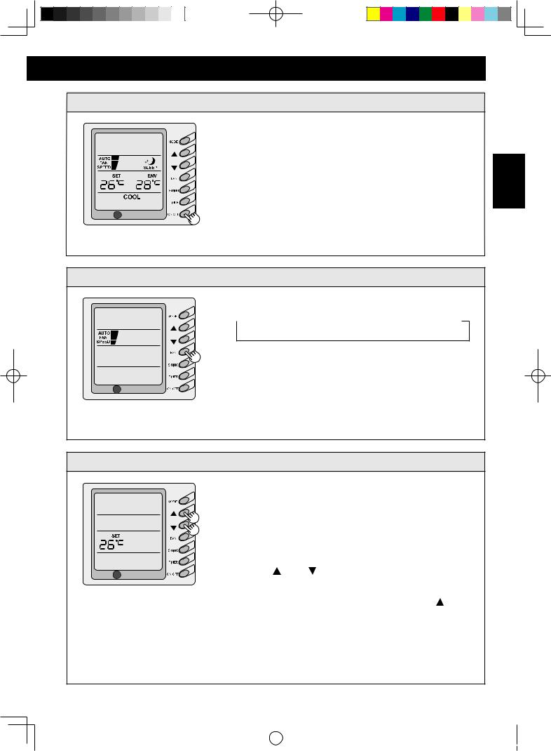
Swing mode setting
•Press “SWING" button.
The "SWING" will be displayed and the louvres will swing.
• To stop swing, repressing the “SWING” button. The "SWING" will be disappeared.
Operation mode setting
• Press the MODE button to select the operation mode.
 COOL
COOL DRY
DRY FAN
FAN HEAT
HEAT AUTO
AUTO
COOL mode
The set temperature must be lower than the room temperature. If the set temperature is higher than the room temperature, the unit will not produce cooling effect, only the fan is active.
DRY mode
Fan moter will run at low fan speed in a specific temperature range. The dehumidifying effect in this mode is better than that in the COOL mode and it is more energy saving.
HEAT mode
The set temperature must be higher than the room temperature. If the set temperature is lower than the room temperature, the heating function will not be activated.
AUTO mode
The unit will adjust its operating mode automatically according to the ambient temperature.
•In heating operation, the outdoor temperature is low and the humidity is hight, frost will produce on the outdoor unit. The heating efficiency will be reduced. In this case, the unit will automatically start to defrost, and the wire controller displays “DEFROST”.
E-
|
|
|
|
|
|
|
|
|
|
|
|
|
|
|
|
GREE_cassette_eng.indd 6 |
|
08.10.28 11:42:41 AM |
|
|
|
||
|
|
||||||
|
|
|
|
|
|
|
|
TIMER setting
•When the unit is not operating, timer start can be set. When the unit is operating, timer shutoff can be set. The range of timer setting is between 0.5 to 24 hours.
1 Press the TIMER button.
The word “TIMER” will flash on the display.
2 Press the buttons ( ) or ( ) to increase or decrease the set time.
3 Press the TIMER button again. The timer will go into effect. The unit will start to count the time passed.
To cancel the timer setting, press the TIMER button.
NOTE:
When the protection or malfunction happens after the timer on was set up, the time place will display the protection or the error codes, the timer button cannot be set up, but the time you have set up before is still available.
ENGLISH
Display of outdoor temperature
Under normal condition, The “ENV” and the room temperature are displayed.
Press “SWING” button for 5 seconds. The “OUT ENV” will be displayed.
• The outdoor temperature will show in the display for 10 seconds, and then return to the room temperature.
E-
|
|
|
|
|
|
|
|
|
|
|
|
|
|
|
|
GREE_cassette_eng.indd 7 |
|
08.10.28 11:42:41 AM |
|
|
|
||
|
|
||||||
|
|
|
|
|
|
|
|
WIRE CONTROL OPERATION
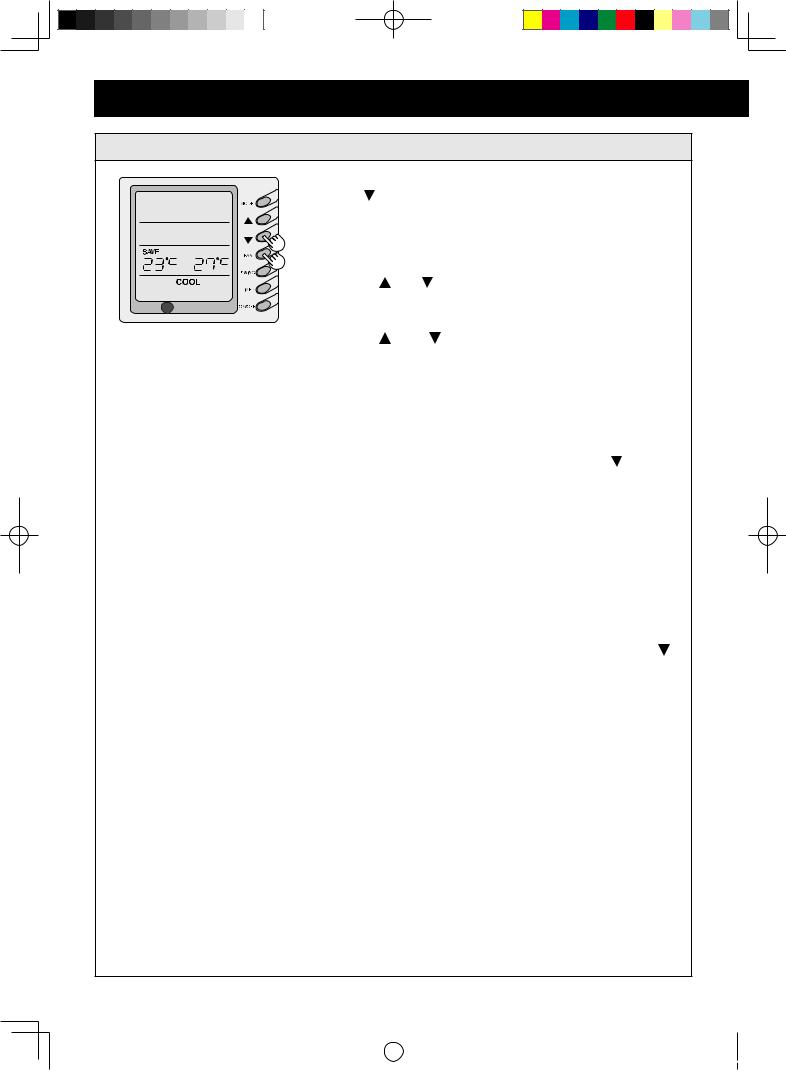
SAVE setting
When the unit is shut off, press the FAN button and the ( ) button continuously for 5 seconds to activate the SAVE setting menu. The “SAVE” and “COOL” will be displayed. (For the first setting, the initial value will be displayed :26). The lower limit temperature will be displayed on the set temperature area and the temperature value will be flashed.
Press ( )and( )buttons to set the cooling lower limit temperature (The setting range: 16-30).
Press ON/OFF button to confirm the setting.
Press ( ) and ( ) buttons to set cooling upper limit temperature and the temperature value will flash on the ambient temperature area (The setting range: 16-30).
Press ON/OFF button to confirm the setting.
Press MODE button to complete the SAVE setting in
COOL and DRY modes, and turn to the SAVE setting in
HEAT mode. The “SAVE” and “HEAT” will be displayed.
After setting is completed, press the FAN and ( ) buttons for 5 seconds to exit the SAVE setting menu. If the SAVE interface has been opened, the system will respond to the last button input after 20 seconds, there is no any operation, the system will quit the menu, and return to the normal unit off display.
After the above settings are completed, the ”SAVE” will be displayed. The set temperature will not exceed the temperature range of the SAVE setting. For example, the lower cooling limit is set to 23˚C and the upper cooling limit is set to 27˚C, so the cooling temperature can only be selected between 23˚C to 27˚C by the wire control or the remote controller.
To cancel the SAVE setting, press the FAN and ( ) buttons for 5 seconds when the unit is turned off. The former setting data will not clear, and the next time SAVE setting will be the initial setting temperature.
NOTE:
•The upper limit temperature should not be lower than the setting lower limit temperature. If upper limit temperature is lower than the lower limit temperature, the system will default the higher as the upper limit temperature, the lower as the lower limit temperature.
•If the upper limit temperature is the same as the lower limit temperature, the system can only operate at this temperature under corresponding mode.
•After the unit is disconnected to power supply, the
SAVE settng will be memorized. The next time power on, the SAVE setting is still active.
•If the SAVE mode is set, the sleep mode and AUTO mode will be invalid.
E-
|
|
|
|
|
|
|
|
|
|
|
|
|
|
|
|
GREE_cassette_eng.indd 8 |
|
08.10.28 11:42:41 AM |
|
|
|
||
|
|
||||||
|
|
|
|
|
|
|
|
Memory function setting
When the unit is shut off, press the MODE button for 10 seconds to switch set values so as to decide if the unit operating status or shut off status is memorized after a power fail.
If the set temperature area displays "01", it means the unit operating status or shut off status shall be memorized after a power fail; "02" means the operating status or shut off status will not be memorized.
Press the ON/OFF button to store the set value and exit the setting.
Even if the ON/OFF button is not pressed, the system will store the set value and exit the setting after 10 seconds, and return to the normal unit off display.
Failure display
When there is failure in the unit operation, the “ERROR” will flash on the display of the wire controller and the error code will also be displayed. When there are multiple failures, the error codes will be displayed one after one on the wire controller. The two digits indicate the detailed the error code.
ENGLISH
The Error Codes Definitions are as Follows:
Error code |
Fault |
E0 |
Water pump malffunction |
E1 |
High pressure protection of compressor |
E2 |
Indoor anti-frozen of compressor |
E3 |
Low pressure protection of compressor |
E4 |
Air discharge high-temperature protection of compressor |
E5 |
Overload protection of compressor |
E6 |
Transmit malfunction |
E8 |
Indoor fan protection |
E9 |
Water flow protection |
F0 |
Malfunction of indoor environment sensor at air return vent |
F1 |
Evaporator sensor malfunction |
F2 |
Condenser sensor malfunction |
F3 |
Outdoor environment sensor malfunction |
F4 |
Malfunction of air discharge sensor |
F5 |
Malfunction of environment sensor on displayer |
FF |
Connected control communications Failure |
EE |
Buttons are locked (not failure) |
E-
|
|
|
|
|
|
|
|
|
|
|
|
|
|
|
|
GREE_cassette_eng.indd 9 |
|
08.10.28 11:42:42 AM |
|
|
|
||
|
|
||||||
|
|
|
|
|
|
|
|
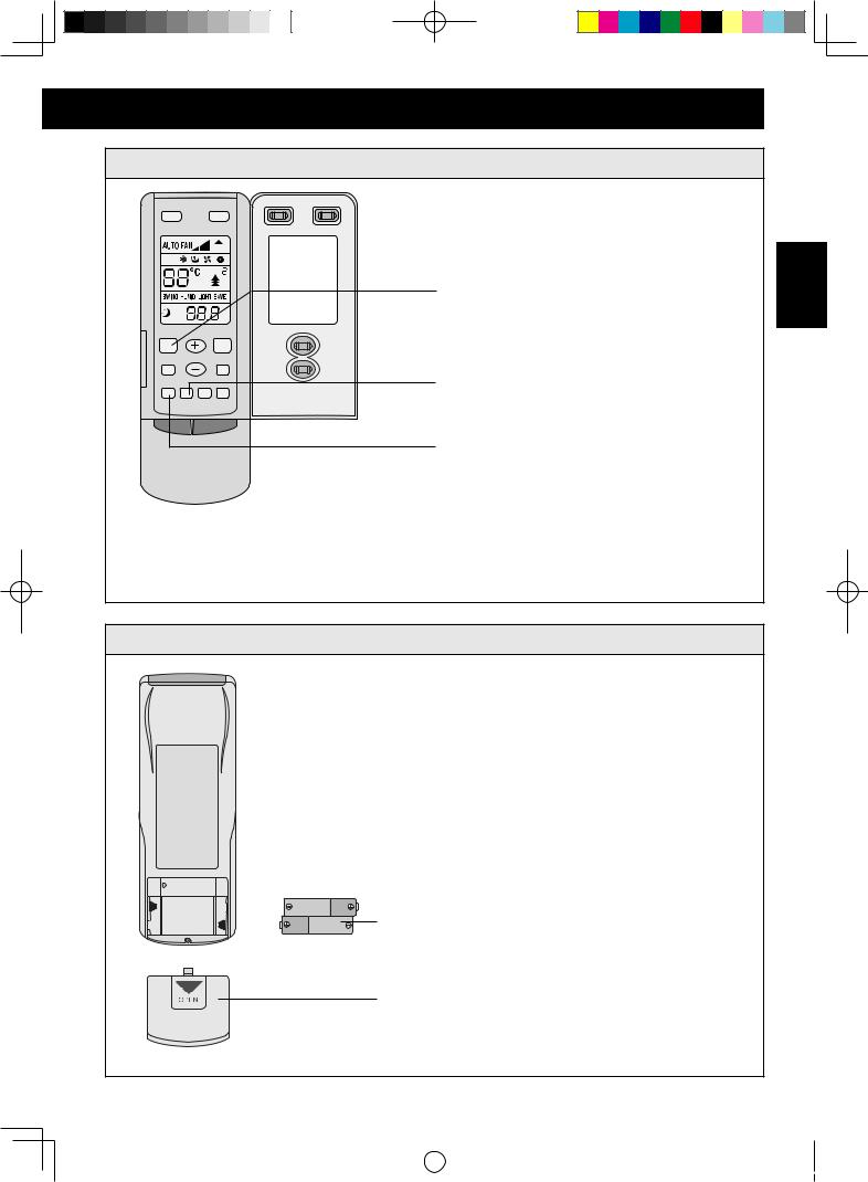
REMOTE CONTROLLER OPERATION
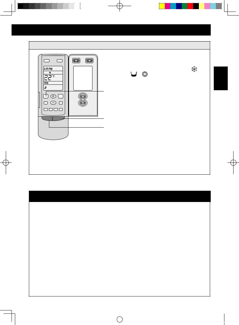
Name and Function
NOTE:
•Be sure that there are no obstructions between receiver and remote controller.
•Do not leave the remote control in direct sunlight or near a heater. Also, protect the unit and remote control from moisture and shock which can discolour or damage them.
SWING button
Press to swing and stop the louvres.
SWING FAN
|
OPER |
AUTO |
|
|
AIR |
TIMER |
|
ON/OFF |
HR. |
TEMP. button
Press to set suitable
TEMP.
MODE button |
MODE ON/OFF |
Press to set  operation AUTO mode.
"  " COOL mode "
  " DRY mode "
  " FAN mode "
  " HEAT mode
FAN button |
|
Press to |
|
change |
AUTO FAN |
the fan |
|
speed. |
|
ON/OFF button
Press to start or stop operation.
 Receiver window
Receiver window |
E-10
|
|
|
|
|
|
|
|
|
|
|
|
|
|
|
|
GREE_cassette_eng.indd 10 |
|
08.10.28 11:42:42 AM |
|
|
|
||
|
|
||||||
|
|
|
|
|
|
|
|
Name and Function (Open the cover )
SWING |
FAN |
|
OPER |
AUTO |
|
|
AIR |
TIMER |
|
ON/OFF |
HR. |
SLEEP AIR
LIGHT HUMID
TIMER ON TIMER OFF ANION |
SAVE |
MODE ON/OFF
SLEEP button
Press this button to set or cancel SLEEP operation.
TIMER OFF button
At operating, press TIMER OFF button, set OFF TIME in range of 0 to 24 hour to stop the unit automatically.
TIMER ON button
At stopping, press TIMER ON button, set ON TIME in range of 0 to 24 hour to start the unit automatically.
NOTE:
Some buttons of the controller which are not available to this air conditioner will not be described above.
Loading batteries
ACL 
2
1
3
1 Remove the cover from the back of the remote controller.
2 Insert the two batteries "R03(AAA)" and press button "ACL" .
3 Reinstall the cover.
NOTE:
•When you replace the batteries, always change both batteries, and make sure they are the same type.
•If you will not be using the unit for a long time, remove the batteries from the remote control.
•The remote control can send signals from up to 10 metres away.
E-11
ENGLISH
|
|
|
|
|
|
|
|
|
|
|
|
|
|
|
|
GREE_cassette_eng.indd 11 |
|
08.10.28 11:42:42 AM |
|
|
|
||
|
|
||||||
|
|
|
|
|
|
|
|

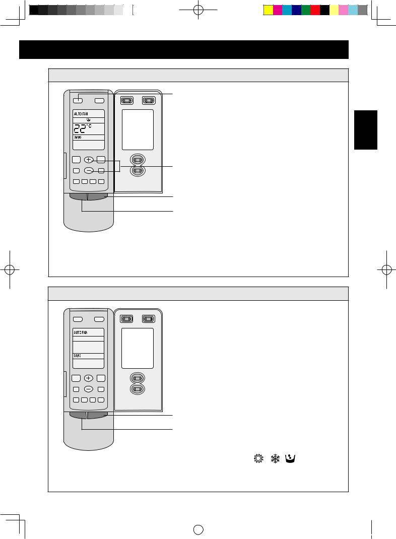
REMOTE CONTROLLER OPERATION
COOL mode operation
SWING FAN
OPER
SLEEP AIR
LIGHT HUMID
TIMER ON TIMER OFF ANION |
SAVE |
MODE ON/OFF
3
4
5
1
2
1Press the ON/OFF button.
2Press the MODE button to select COOL( ) mode.
3Press the SWING button. The louvres will swing, and stop when repress.
4Press the FAN button to select fan speed.
5Press the Temperature button to set the desired temperature.
•If room temperature is lower than set temperature, compressor stops and only indoor fan motor runs.
•The temperature can be set within the range of 16˚C to 30˚C.
HEAT mode operation
SWING FAN
OPER
SLEEP AIR
LIGHT HUMID
TIMER ON TIMER OFF ANION |
SAVE |
MODE ON/OFF
3
4
5
1
2
1Press the ON/OFF button.
2Press the MODE button to select HEAT( ) mode.
3Press the SWING button. The louvers will swing, and stop when repress.
4Press the FAN button to select fan speed.
5Press the Temperature button to set the desired temperature.
•If room temperature is higher than set temperature, compressor and outdoor fan motor stop, only indoor fan motor runs.
•The temperature can be set within the range of 16˚C to 30˚C.
E-12
|
|
|
|
|
|
|
|
|
|
|
|
|
|
|
|
GREE_cassette_eng.indd 12 |
|
08.10.28 11:42:43 AM |
|
|
|
||
|
|
||||||
|
|
|
|
|
|
|
|
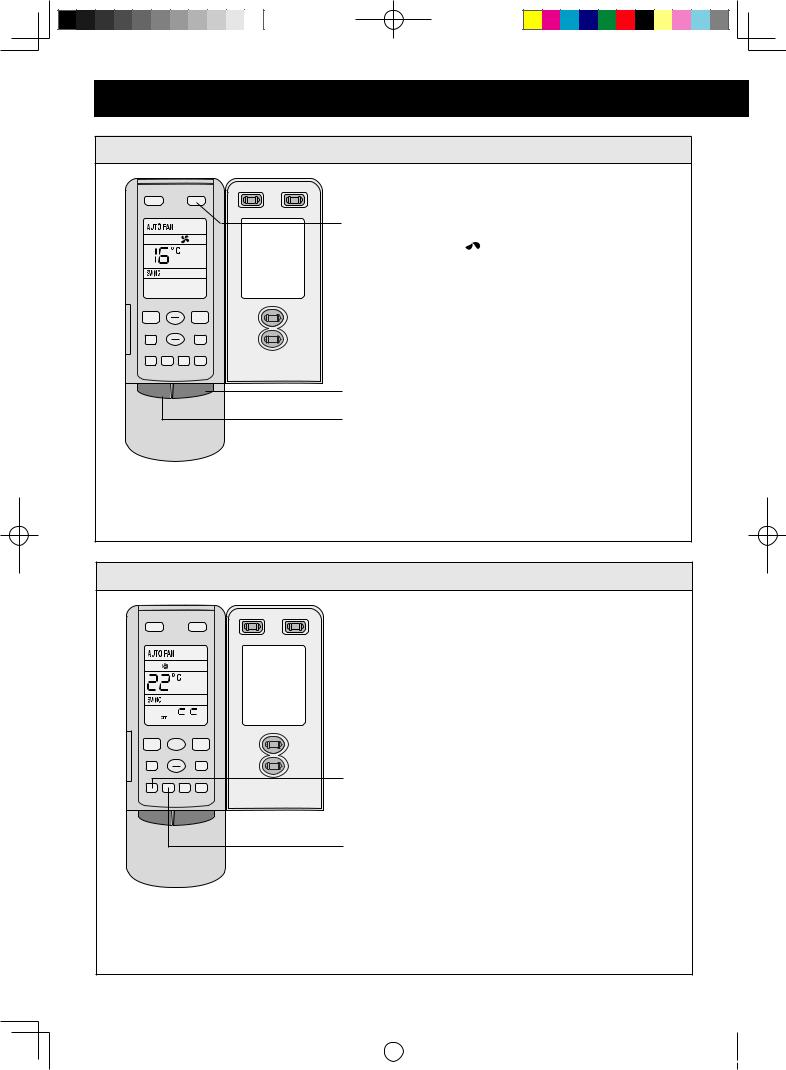
DRY mode operation
SWING FAN
OPER
3 1Press the ON/OFF button.
2Press the MODE button to select DRY( ) mode.
3Press the SWING button, the louvers will swing, and stop when repress it..
4Press the Temperature button to set the desired temperature.
SLEEP |
AIR |
4 |
|
LIGHT |
HUMID |
||
TIMER ON TIMER OFF ANION SAVE |
1 |
||
MODE |
ON/OFF |
||
|
|||
|
|
2 |
|
•If room temperature is lower than set temperature, compressor, outdoor and indoor fan motor stop. If room temperature is between ±2˚C of set temperature, air conditioner is drying. If room temperature is higher than set temperature, it’s at COOL mode.
•The temperature can be set within the range of 16˚C to 30˚C.
AUTO mode operation
SWING FAN
OPER
AUTO
SLEEP AIR
LIGHT HUMID
TIMER ON TIMER OFF ANION |
SAVE |
MODE ON/OFF
1
2
1Press the ON/OFF button.
2Press the MODE button to select AUTO mode.
• |
According to room temperature, the unit will automatically set |
, |
, |
mode. |
• |
In AUTO mode operation, standard temperature is 26˚C for COOL mode, 24˚C for DRY |
|||
|
mode and 20˚C for HEAT mode. |
|
|
|
E-13
ENGLISH
|
|
|
|
|
|
|
|
|
|
|
|
|
|
|
|
GREE_cassette_eng.indd 13 |
|
08.10.28 11:42:43 AM |
|
|
|
||
|
|
||||||
|
|
|
|
|
|
|
|
REMOTE CONTROLLER OPERATION
FAN mode operation
SWING FAN
OPER
SLEEP AIR
LIGHT HUMID
TIMER ON TIMER OFF ANION |
SAVE |
MODE ON/OFF
1Press the ON/OFF button.
3 2Press the MODE button to select FAN( ) mode.
3Press the FAN button to select from high, medium and low speed.
1
2
TIMER operation
SWING FAN
OPER
TIMER

 HR.
HR.
SLEEP AIR
LIGHT HUMID
TIMER ON TIMER OFF ANION |
SAVE |
MODE ON/OFF
1At stopping, press the TIMER ON button, set ON TIMER in range of 0 to 24 hour to start the unit automatically.
2At operating, press the TIMER OFF button, set OFF TIMER in range of 0 to 24 hour to stop the unit automatically.
1
2
E-14
|
|
|
|
|
|
|
|
|
|
|
|
|
|
|
|
GREE_cassette_eng.indd 14 |
|
08.10.28 11:42:44 AM |
|
|
|
||
|
|
||||||
|
|
|
|
|
|
|
|
SLEEP mode operation
SWING FAN
OPER
SLEEP AIR
LIGHT HUMID
TIMER ON TIMER OFF ANION |
SAVE |
MODE ON/OFF
3
1
2
1Press the ON/OFF button.
2Press the MODE button to select 
 ,
,  or mode.
3Press the SLEEP button to set SLEEP operation.
•When SLEEP operation is set during cooling or dry operation, the temperature setting rises
1˚C in 1 hour and 2˚C in 2 hours.
•When SLEEP operation is set during heating operation, the temperature setting drops 1˚C in 1 hour and 2˚C in 2 hours.
•Indoor fan motor runs at low speed.
ENGLISH
OPTIMUM OPERATION
ADJUST THE ROOM TEMPERATURE PROPERLY.
• Adjust the room temperature properly for a comfortable environment.
NEVER PLACE ANYTHING UNDER THE INDOOR UNIT THAT IS TO BE KEPT DRY.
•Water may drop from the indoor unit when the humidity is over 80% or when the drainage outlet is clogged.
DISCONNECT THE POWER CORD WHEN THE UNIT IS NOT USED FOR AN EXTENDED PERIOD OF TIME
• The indoor unit still consumes a small amount of power when it is not operating.
BLOCK DIRECT SUNLIGHT AND PREVENT DRAFTS
•Blocking direct sunlight during cooling operation will reduce power consumption.
•Close the windows and doors during cooling operation.
E-15
|
|
|
|
|
|
|
|
|
|
|
|
|
|
|
|
GREE_cassette_eng.indd 15 |
|
08.10.28 11:42:44 AM |
|
|
|
||
|
|
||||||
|
|
|
|
|
|
|
|
TROUBLE SHOOTING
Warning
•If anything is abnormal with the air conditioner (ex. a burning smell), stop the operation immediately and turn the circuit breaker OFF.
•Do not repair the air conditioner by yourself. Wrong repair may cause fire. please contact service center.
If the unit appears to be malfunctioning, check the following points before calling for service.
|
Symptom |
Cause |
Corrective measures |
|
The unit does not |
Phase reverse or fuse broken |
Change phase or replace fuse |
|
operate at all |
|
|
|
Power off |
It will restart when power is on |
|
|
|
Loose plug |
Put the plug into place |
|
|
Batteries of remote controller fall |
Replace batteries |
|
|
Out of the remote controlling range |
Keep distance in 10 m or less |
|
Operation stops |
There is obstacle at the air intake or outlet. |
Remove it |
|
suddenly |
|
|
|
The unit fails to |
There is obstacle at the air intake or outlet. |
Remove it |
|
cool (or heat) the |
Wrong temperature setting |
Refer to p.5 |
|
room effectively |
|
|
|
Low fan speed |
Refer to p.5 |
|
|
|
||
|
|
Air direction is not correct |
Refer to p.6 |
|
|
The door or window is open. |
Close them |
|
|
Direct sunshine |
Close the curtain or blinder |
|
|
There is heat source or too many people in the |
|
|
|
room. |
|
|
|
The air filter is dirty or blocked. |
Clean it |
The following conditions do not denote equipment malfunctions |
|
||
|
|
|
|
|
Symptom |
Trouble |
Cause |
|
The unit does not |
when you restart the unit |
This is to protect the internal |
|
operate |
|
mechanisms. Wait 3 minutes before |
|
|
|
operating the unit. |
|
|
when power is switched on |
Wait for 1 minute |
|
Mists come out |
when cooling |
Room air is chilled rapidly and |
|
|
|
becomes foggy |
|
Outdoor unit is hot |
after the unit is stopped |
Compressor is emitting heat to get |
|
|
|
ready for restarting |
|
Noise |
Buzz is heard at starting |
It's the starting sound of thermostat |
|
|
|
and will turn low after 1 minute |
|
|
Sound of running water can be heard during |
This is caused by the refrigerant |
|
|
operation |
flowing inside the unit |
|
|
A "shuh" sound is heard when unit starts/stops |
This is the noise of refrigerant caused |
|
|
operation or defrost. |
by flow stop and flow change |
|
|
A continuous low "shah" sound is heard during |
The noise is heard when the drainage |
|
|
cooling operation or at a stop. |
pump is in operation |
|
|
Cracking noise can be heard during or after |
This sound is generated by the |
|
|
operation |
friction of the front panel and other |
|
|
|
components expanding or connecting |
|
|
|
due to a temperature change |
|
Dust from the unit |
Starting operation after not using for a long time. |
Dust absorbed by the unit blows out |
|
Odors |
During operation |
Carpet and furniture odors that |
|
|
|
entered into the unit may be sent out |
|
|
|
from the unit |
E-16
|
|
|
|
|
|
|
|
|
|
|
|
|
|
|
|
GREE_cassette_eng.indd 16 |
|
08.10.28 11:42:44 AM |
|
|
|
||
|
|
||||||
|
|
|
|
|
|
|
|
CARE AND MAINTENANCE
Warning
•Be sure to disconnect the power cord from the wall outlet or turn off the circuitbreaker before performing any maintenance.
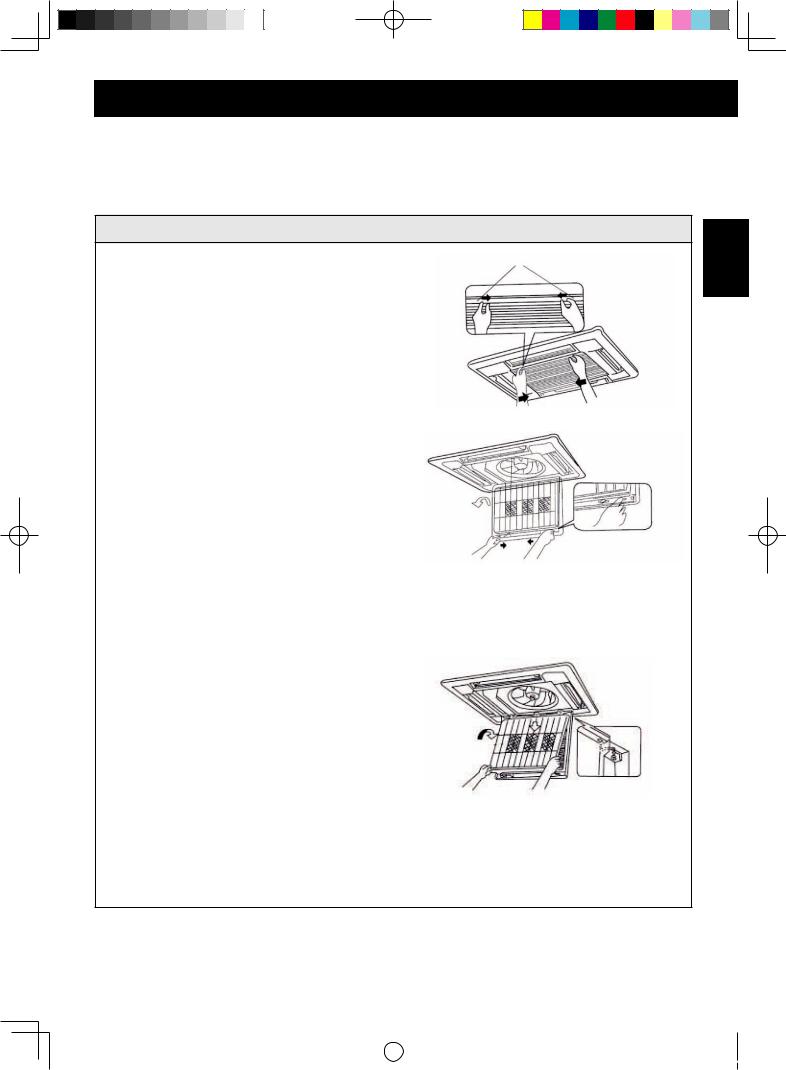
How to clean the air filter
Open the suction grille |
Screws |
1 Unscrew the two screws. |
|
Slide both knobs simultaneously as shown |
|
and pull them downward slowly. |
|
2 Remove the air filter
Slide knobs on the back of the suction grille outward and remove the air filter.
Then remove three air cleaners on it.
3 Clean the air filter
Use a vacuum cleaner to remove dust. If the
fiilter is dirty, wash it with warm water and a mild detergent. Dry fiilter in the shade before reinstalling.
• Do not clean with hot water.
• Do not dry over fire.
• The suction grille must be opened by skilled personnel.
4 Fix the air filters
•Fix three air cleaner on the air filter and then fix the air filter to the suction grille by hanging it to the projected portion above suction grille.
•Set air filter by sliding the knob on the back of the suction grille inward.
5 Close the suction grille. (Refer to step 1.)
E-17
ENGLISH
|
|
|
|
|
|
|
|
|
|
|
|
|
|
|
|
GREE_cassette_eng.indd 17 |
|
08.10.28 11:42:44 AM |
|
|
|
||
|
|
||||||
|
|
|
|
|
|
|
|
CARE AND MAINTENANCE
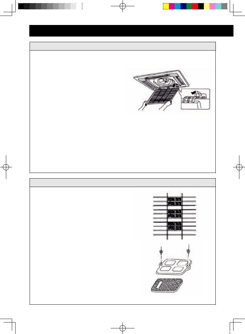
How to clean the suction grille
1 Open the suction grille. (See step 1 of
"How to clean the air filter")
2 Remove the air filter. (See step 2 of "How to clean the air filter")
3 Remove the suction grille.
Open the suction grille at 45˚ and then lift.
4 Wash with water.
When the suction grille is very dirty, use soft brush and neutral detergent. Shake off water and dry in a shady place.
Do not wash with hot water.
5 Fix the suction grille. (Refer to step 3.)
6 Fix the air filter. (See step 4 of "How to clean the air filter")
7 Close the suction grille. (Refer to step 1.)
Changing air cleaner
1 Open the suction grille. (See step 1 of
"How to clean the air filter")
2 Remove the air cleaner.
Remove the air filter, and remove the air cleaner after unscrewing.
3 Take off packing bag and put in new static electricity fiber filer, then fix them on the air filter.
4 Fix the air filter. (See step 4 of "How to clean the air filter")
E-18
GREE_cassette_eng.indd 18
08.10.28 11:42:45 AM
|
|
|
|
|
|
|
|
|
|
|
|
|
|
|
|
|
|
|
|
|
|
|
|
|
|
|
|
|
|
|
|
|
|
|
|
|
|
|
|
|
|
|
|
|
|
|
|
|
|
|
|
|
|
|
|
|
|
|
|
|
|
|
|
|
|
|
|
|
|
|
|
|
|
|
|
|
|
|
|
|
|
|
|
|
|
|
|
|
|
|
|
|
|
|
|
|
|
|
|
|
|
|
|
|
|
|
|
|
|
|
|
|
|
|
|
|
|
|
|
|
|
|
|
|
|
|
|
|
|
|
|
|
|
|
|
|
|
|
|
|
|
|
|
|
|
|
|
|
|
|
|
|
|
|
|
|
|
|
|
|
|
|
|
|
|
|
|
|
|
|
|
|
|
|
|
|
|
|
|
|
|
|
|
|
|
|
|
|
|
|
|
|
|
|
|
|
|
|
|
|
|
|
|
|
|
|
|
|
|
|
|
|
|
|
|
|
|
|
|
|
|
|
|
|
|
|
|
|
|
|
|
|
|
|
|
|
|
|
|
|
|
|
|
|
|
|
Air cleaner functions and service cycle time |
|
|
||||||||||||||||||||
|
|
|
|
|
|
|
• |
Absorbs bad smell in air such as carbon monoxide carbon dioxide, benzol, gasoline and |
|
|
|||||||||||||||||||
|
|
|
|
|
|
|
|
so on. |
|
|
|||||||||||||||||||
|
|
|
|
|
|
|
• |
Absorbs harmful objects bigger than 1.0 mm in air such as dust, pollen, germ, virus and |
|
|
|||||||||||||||||||
|
|
|
|
|
|
|
|
so on. |
|
ENGLISH |
|||||||||||||||||||
|
|
|
|
|
|
|
• |
It can be used for about half a year to one year. |
|
||||||||||||||||||||
|
|
|
|
|
|
|
|
|
|||||||||||||||||||||
|
|
|
|
|
|
|
|
|
|
|
|
|
|
|
|
|
|
|
|
|
|
|
|
|
|
|
|
|
|
How to clean the air outlet and case
•Clean with soft cloth or use water and neutral detergent.
•Do not use gasoline, benziene, thinner, polishing powder, liquid insecticide, which may cause discoloring or warping. If the air flow flap is very dirty, you may remove it to clean as shown below.
1.Detach the flap
Loosen the screws on the sides of the flap.
(Not including GX-X18JR)
2.Fix the flap
Set the ribs on the sides of the air outlet to the slit of the flap and then screw together to fix the flap.
Maintenance before air conditioner season
1Make sure that nothing obstructs the air inlet or outlet.
2Make sure that ground wire is connected and that it is not damaged.
3 Make sure that air filters are not dirty.
4Turn on the power 6 hours before starting the air conditioner.
Maintenance after air conditioner season
1 Clean the filters, then reinstall them.
2Turn off power.
3Clear outdoor unit of dust.
4If there is any rust in the outdoor unit, paint over it to prevent the rust from spreading.
E-19
|
|
|
|
|
|
|
|
|
|
|
|
|
|
|
|
GREE_cassette_eng.indd 19 |
|
08.10.28 11:42:45 AM |
|
|
|
||
|
|
||||||
|
|
|
|
|
|
|
|
INSTALLATION INSTRUCTIONS
Iinstallation notes
Location
•The air conditioner must be firmly installed and 3~4 liability checks must be done every year.
•Avoid place within easy reach of young children.
•Keep TV set, radio and the like 1 m or more away from the unit and the remote controller.
•Do not install the unit in a place where inflammable gas may leak. It may cause fire.
•At salty coastal areas or special areas such as the vicinity of a sulphurous hot spring, please contact dealer before installation to make sure it is safe to use the unit.
•Not to be installed in laundries.
•Select a place so as not to annoy neighbor with the hot air or noise.
Installatton/removal/repair
•Do not attempt to install/remove/repair the unit by yourself. Incorrect work will cause electric shock, water leak, fire etc. Consult your dealer or other qualified service personnel for the installation/removal/repair of the unit.
•Be sure to use only the specified accessories and parts for installation, failure to use may lead to electric shock, leakage or fire.
•Carry out installation with consideration of strong winds, typhoons, or earthquakes. Improper installation work may result in accidents due to fall of equipment.
Wiring arrangement
•Prepare a dedicated power supply circuit.
•The cable must be installed by professional technicians.
•If the supply cord is damaged, it must be replaced by the manufacturer or its service agent or a similarly qualifiied person in order to avoid a hazard. Use only the manufacture-specifiied power cord for replacement.
•The appliance shall be installed in accordance with national wiring regulations. Improper cable connection can cause the power supply cord, plug and the electrical outlet to overheat and cause fiire.
•Fit a disconnect switch, having a contact separation of at least 3mm in all poles, to the electricity power line.
Indoor unit installation
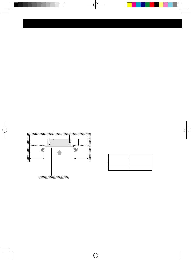
Installation spaces
|
MIN.20 |
|
H |
MIN.1500 |
MIN.1500 |
|
MIN.1800 |
Length unit: mm
Model |
H(mm) |
GX-X18JR |
230 |
GX-X24JR |
260 |
GX-X36JR |
340 |
Selection of the installation site
•There shall be no obstacle at the inlet and outlet so as to keep the air in good circulation.
•Ensure the space needed for installation, repair and maintenance works.
•The horizontally of the installation place should be guaranteed.
•The drainage hose shall be easy to drain water.
•Make sure that there are enough space for care and maintenance. Make sure that the height between the indoor unit and ground is above 1800mm.
•When installing the lifting bolt, check if the install place can withstand the weight 4 times of the unit’s. If not, reinforce before installation. (Refer to the model paper and find where should be reinforced)
NOTE:
There will be substantial amount of lampblack and dust in dining room and kitchen, which would reduce the capacity of heat exchanger, result in water leakage and abnormal operation of the water pump.
•Ensure that the smoke trap above cooker has enough capacity to prevent the indraft of the lampblack by the air conditioner.
•Install the air conditioner far from the kitchen so that the lampblack would not be indraft by the air conditioner.
E-20
|
|
|
|
|
|
|
|
|
|
|
|
|
|
|
|
GREE_cassette_eng.indd 20 |
|
08.10.28 11:42:45 AM |
|
|
|
||
|
|
||||||
|
|
|
|
|
|
|
|
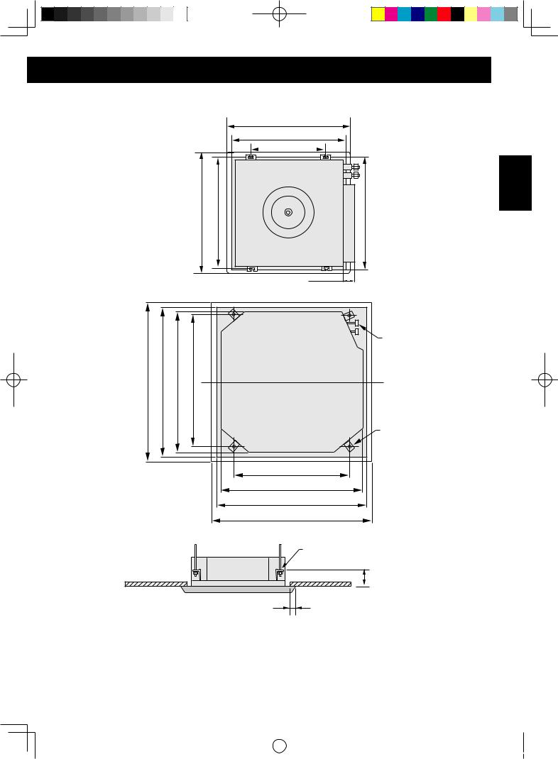
Dimension of ceiling opening and location of the hoisting screw (M10)
GX-X18JR
650 (Grille measurement)
600-610 (Ceiling opening)
400 (Hanging bolt position)
|
|
|
650 (Grille measurement) |
606 (Hanging bolt position) |
600 - 610 (Ceiling opening) |
ENGLISH |
|
|
|
|
|
66 |
|
GX-X24JR/GX-X36JR |
|
|
|
|
||
|
|
|
rods) |
|
|
Refrigerant pipe |
|
|
|
(Gapsbetween hoisting screw |
|
|
|
(Decorated surfaceboards) |
(Ceiling opening) |
(Indoor unit) |
|
|
Hoisting screw (X4) |
|
950 |
890* |
840 |
780 |
|
|
|
|
|
|
||||
680 (Gaps between hoisting screw rods)
840 (Indoor unit) |
|
890 (Ceiling opening) |
|
950 (Decorated surface boards) |
Length unit: mm |
|
|
Installation stands formain body of the unit |
|
160 mm |
Ceiling
Above 20 mm
NOTE:
•The drilling of holes in the ceiling must be done by the professional personnel.
•The dimension for the ceiling openings with * marks can be as large as 910mm. But the overlapping sections of the ceiling and the decorated surface boards should be maintained at no less than 20mm.
E-21
|
|
|
|
|
|
|
|
|
|
|
|
|
|
|
|
GREE_cassette_eng.indd 21 |
|
08.10.28 11:42:45 AM |
|
|
|
||
|
|
||||||
|
|
|
|
|
|
|
|
INSTALLATION INSTRUCTIONS
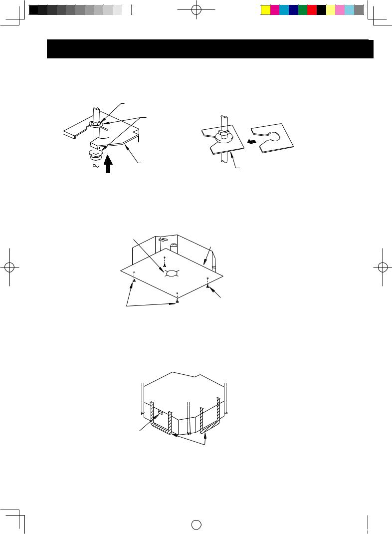
Install the air conditioner
1Attach the articulation on the lifting bolt with the two nuts and washers.
•Use the washer fixed board to prevent washer from falling.
Nut (local parts)
Washer (attachment)
Articulation
Tighten (double nuts)
Insert
Washer fixed board
(attachment)
2Use the model paper.
•Refer to the model paper about the dimension of ceiling opening.
•The central mark of the ceiling opening is marked on the install cardboard.
•Install the install cardboard on the unit by screws (4 piece).
Center of the ceiling opening
Model paper(attachment)
Screw (attachment)
Screw (attachment)
3Adjust the unit to the suitable install place.
4Check if the unit is horizontal.
•Inner drainage pump and float switch are included in the indoor unit, check if 4 angle of every unit are horizontal by water level. (If the unit is slant toward the opposite of the water flow, there may be malfunction of the float switch and lead water drop.)
Water level
Polyethylene tube
5 Remove the washer fixed board and tighten the nut on it.
6 Remove the model paper.
E-22
|
|
|
|
|
|
|
|
|
|
|
|
|
|
|
|
GREE_cassette_eng.indd 22 |
|
08.10.28 11:42:45 AM |
|
|
|
||
|
|
||||||
|
|
|
|
|
|
|
|
Connect the refrigerant pipe
Selection of refrigerant pipe
Item |
Size of fitting pipe |
Max. Pipe length |
Max. Height difference |
Amount of additional |
|
|
|
|
|
between indoor unit |
refrigerant to be filled (for |
|
|
|
|
and outdoor unit |
extra length of pipe) |
Model |
Gas pipe |
Liquid pipe |
|
||
|
|
|
|||
GX-X18JR |
1/2˝ |
1/4˝ |
20 m |
15 m |
30g/m |
GX-X24JR |
5/8˝ |
3/8˝ |
30 m |
15 m |
60g/m |
GX-X36JR |
3/4˝ |
1/2˝ |
50 m |
30 m |
120g/m |
NOTE:
• The standard pipe length is 5m. If the pipe length exceed 5m, add refrigerant. (As shown in above table)
• Use pipes with thickness 0.8mm(1/4˝, 3/8˝, 1/2˝), 1.0mm(5/8˝), 1.2mm(3/4˝). The pipe wall shall be able to withstand the pressure of 6.0 MPa.
• The longer the refrigerant pipe, the lower the cooling effect and the heating effect.
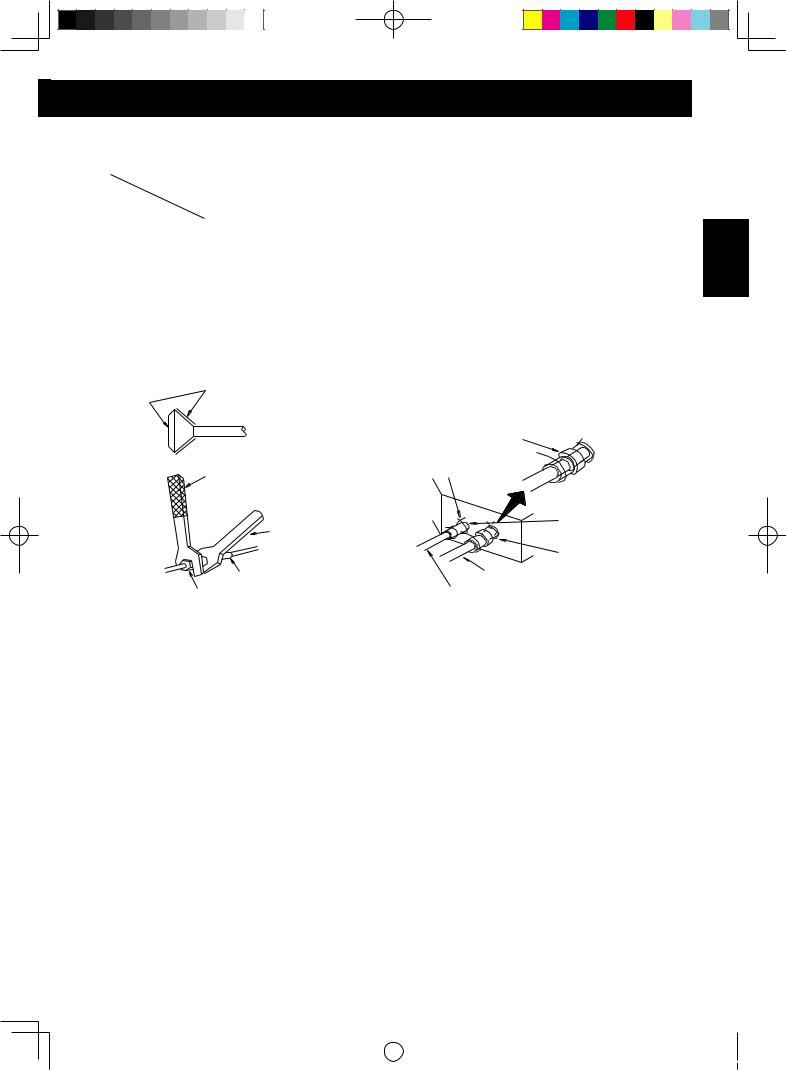
Smear freeze motor oil here
Torque wrench
Wrench
Flare nut
Medial sponge (attachment) (Wrap the piping interface with seal mat)
Fixing band (x4)
Heat insulation (attachment) (for liquid pipe)
Heat insulation (attachment)(for gas pipe)
Gas pipe
Liquid pipe
• |
When connect the pipe to the unit, use both wrench and torque wrench. |
||||
• |
When connect, smear both inside and outside of the flare nut with freeze motor oil, screw it by |
||||
• |
hand and then tighten it with spanner. |
||||
See the table below for the flare nut tightening torque. (too tight would damage the flare nut |
|||||
|
and gas leakage). |
|
|
|
|
|
|
|
|
|
|
|
Pipe Diameter |
|
Pipe thickness |
Tightening torque |
|
|
1/4" |
|
0.8mm |
16±2 (N·m) |
|
|
3/8" |
|
0.8mm |
38±4 (N·m) |
|
|
1/2" |
|
0.8mm |
55±6 (N·m) |
|
|
5/8" |
|
1.0mm |
75±7 (N·m) |
|
|
3/4" |
|
1.2mm |
110±10 (N·m) |
|
• Check the refrigerant pipe for gas leakage, then insulate the pipes with heat insulation.
• Wrap median sponge around the gas pipe and heat insulation.(Gas side only)
ENGLISH
E-23
|
|
|
|
|
|
|
|
|
|
|
|
|
|
|
|
GREE_cassette_eng.indd 23 |
|
08.10.28 11:42:46 AM |
|
|
|
||
|
|
||||||
|
|
|
|
|
|
|
|
INSTALLATION INSTRUCTIONS
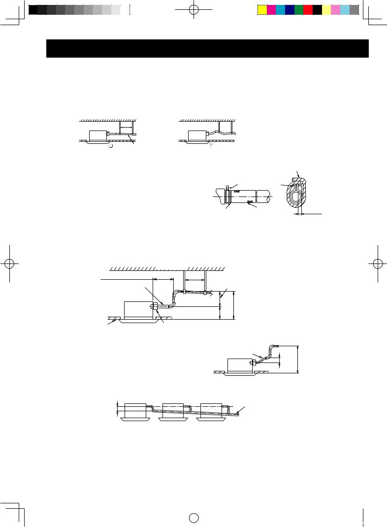
Install drain hose
•The diameter of the drain hose should be equal or bigger than the connection pipe’s. ( The diameter of polythene pipe: Outer diameter 25mm surface thickness 1.5mm)
•Drain hose should be short and falling gradient should more than 1/100 to prevent the formation of air bubble.
•If drain hose cannot has enough falling gradient, drain raising pipe should be added.
•To prevent bent of the drain hose, the distance between hoisting stand should is 1m to 1.5m.
1-1.5m
(Correct) 1/100 or more gradient |
(wrong) |
•Use the drain hose and clamp with the provided attachment. Insert the drain hose to the drain vent, and then tighten the clamp.
•Wrap the big sponge on the clamp of drain hose to insulate heat.
•Heat insulation should be done to indoor drain hose.
Big sponge(attachment)
Clamp Clamp(attachment)
Sponge (gray) Drain hose |
Below 4mm |
|
Note of drain raising pipe
• The install height of the drain raising pipe should less than 280mm.
• The drain raising pipe should form a upright angle with the unit, and distance to unit should not beyond 300mm.
Within 300mm Drain hose (attachment)
Ceiling
Roof
1-1.5m Hoisting stand
|
Below 280mm |
|
Drain raising |
500mm |
|
pipe |
|
|
|
220mm |
Below |
Clamp(attachment) |
|
|
|
|
|
• The slant gradient of the attached drain hose |
|
should be within 75mm so that the drain faucet |
Drain hose(attachment) |
doesn’t has to endure the unnecessary outside |
|
force. |
|
Below 75mm |
Below 500mm |
• Install the drain hose according to the following process if several drain hoses join together.
Above100mm
The specs of the selected join drain hose should fit the capacity of the unit.
•Check the smoothness of drain after installation.
•Check the drain by pouring 600cc water slowly into the outlet vent or test hole.
•Check the drain in cooling operation after installation of the electric circuit.
E-24
|
|
|
|
|
|
|
|
|
|
|
|
|
|
|
|
GREE_cassette_eng.indd 24 |
|
08.10.28 11:42:46 AM |
|
|
|
||
|
|
||||||
|
|
|
|
|
|
|
|
|
Drain hose |
Test hole cover |
|
|
|
Drain vent for repair use (plastic |
|
Test hole |
stopper is included) (drain the water |
|
|
in waterspout by this outlet vent) |
|
|
Above 100mm |
Pouring water into the test hole |
|
|
Pouring water into the |
Plastic water pot (The length of the |
outlet vent terminal |
pipe should be about 100mm.) |
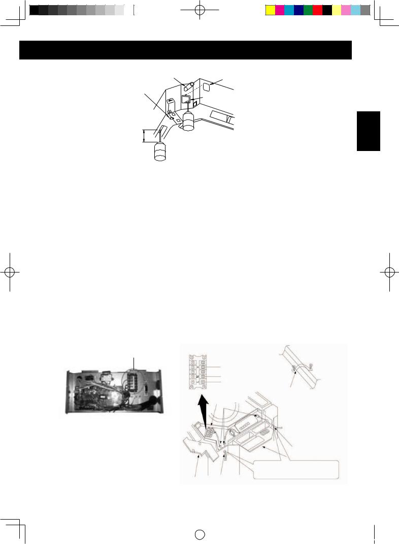
Electric wiring
•Be sure to disconnect all supply circuits in case of wiring work.
•All field supplied parts and materials must conform to local laws and regulations.
•For electric wiring, refer to WIRING DIAGRAM attached to the unit body.
Wiring of the indoor unit.
Remove the control box lid, pull the wires inside through rubber bush A and wiring according to the WIRING DIAGRAM , then tighten it with clamp.
Wiring of the controller
1.Remove the control box lid, pull wires inside through rubber bush B and connect to the controller.
2.Wrap the wire with sealing pad.
3.After wiring, tighten it with clamp and fix the control box lid.
4.Connect the rubber wire (3-cords) to the power supply terminal board in properly.
Precautions:
Be sure to connect the indoor unit and outdoor unit at right poles.
ENGLISH
GX-X18JR
Terminal board
GX-X24JR/GX-X36JR
Power: 220-240V~50Hz
power supply terminal board Clamp
Control box lid (2) Rubber bush A
Clamp
Rubber bush B
Control box lid (2)
Seal here to avoid leakage
E-25
|
|
|
|
|
|
|
|
|
|
|
|
|
|
|
|
GREE_cassette_eng.indd 25 |
|
08.10.28 11:42:46 AM |
|
|
|
||
|
|
||||||
|
|
|
|
|
|
|
|

INSTALLATION INSTRUCTIONS
Installation of panel
GX-X24JR/GX-X36JR:AZ-24J
Fit the swing flap motor position of the panel to the piping position of the indoor unit.
1.Hang the latch, which is located on the opposite side of the swing flap motor on the panel, to the hook of the indoor unit. (2 Positions)
2.Hang the remaining 2 latches to the hooks on the sides of the indoor unit. (Be careful not to get the swing motor lead wire caught in the sealing material.)
3.Screw all 4 hexagon head screws located right beneath the latches in approximately 15mm. (The panel will rise)
4.Adjust the panel by turning it to the arrowed direction in figure so that the ceiling opening is completely covered.
5.Tighten the screws until the thickness of the sealing material between the panel and the indoor unit is reduced to 5~8mm. Hook
Latch
Piping position
Swing flap moter
|
|
|
Sealing material |
||
|
|
Indoor unit |
|||
|
|
|
|
|
|
Ceiling |
|
|
|
|
|
|
|
|
5~8mm |
|
|
|
|
|
|
|
|
GX-X18JR:AZ-18J |
Air outlet |
Panel |
1.Unscrew the 2 screws.
2.Slide the 2 stoppers and remove the front grill.
3.Attach the panel on the indoor unit with the 4 hexagon bolts securely.
4.Replace the front grill and tighten the 2 screws removed in step 1.
E-26
|
|
|
|
|
|
|
|
|
|
|
|
|
|
|
|
GREE_cassette_eng.indd 26 |
|
08.10.28 11:42:46 AM |
|
|
|
||
|
|
||||||
|
|
|
|
|
|
|
|

Caution
1. Improper screwing of the screws may cause the troubles.
Air leak
Air leak from ceiling |
Contamination dew condensation, dew dripping |
|
ENGLISH
2.If gap is still left between the ceiling and the panel after screwing the screws, readjust height of the indoor unit.
Adjustment indoor unit from the holes in the corner of the panel is possible if the indoor unit is kept leveled and the drainage pipe piping etc is unaffected.
No gap is allowed
•After fixing be sure no gap left between the ceiling and the panel
3.Wiring of the panel.
Connect the joints for swing flap motor lead wire installed on the panel to the joints on the indoor unit.(2 places)
Indoor unit Panel
Indoor unit Panel
E-27
|
|
|
|
|
|
|
|
|
|
|
|
|
|
|
|
GREE_cassette_eng.indd 27 |
|
08.10.28 11:42:47 AM |
|
|
|
||
|
|
||||||
|
|
|
|
|
|
|
|
INSTALLATION INSTRUCTIONS
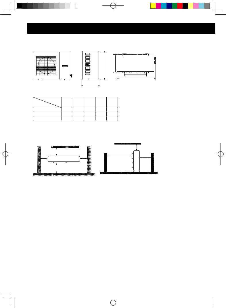
Outdoor unit installation
Dimensions of outdoor unit
|
|
|
|
C |
E |
|
|
|
|
|
D |
|
|
|
|
|
A |
|
|
|
B |
|
|
|
|
|
|
Unit:mm |
|
|
Item |
|
|
|
|
Model |
A |
B |
C |
D |
E |
|
|
|
|
|
|
GU-X18JR |
848 |
320 |
540 |
548 |
286 |
GU-X24JR |
913 |
378 |
680 |
548 |
340 |
GU-X36JR |
1032 |
412 |
1250 |
572 |
378 |
Installation spaces
MIN. |
MIN. 500 |
MIN. |
MIN. 2000 |
MIN. 1000 |
500 |
|
MIN.500 |
||
|
500 |
|
||
|
|
|
||
|
MIN. 2000 |
|
|
|
Unit:mm
Precautions on installation of outdoor unit
To ensure the unit in proper function, selection of installation location must be in accordance with following principles:
• Outdoor unit shall be installed so that the air discharged by outdoor unit will not return and that sufficient space for repair shall be provided around the machine.
• The installation site must have good ventilation, so that the outdoor unit can take in and exhaust enough air. Ensure that there is no obstacle for the air intake and exhaust of the outdoor unit. If there is any obstacle blocking the air intake or exhaust, remove it.
• Place of installation shall be strong enough to support the weight of outdoor unit, and it shall be able to insulate noise and prevent vibration. Ensure that the wind and noise from the unit will not affect your neighbors.
• Avoid direct sunshine over the unit. It is better to set up a sun shield as the protection.
• Place of installation must be able to drain the rainwater and defrosting water.
• Place of installation must ensure the machine will not be buried under snow or subject to the influence of rubbish or oil fog.
• The installation site must be at a place where the air exhaust outlet does not face strong wind.
E-28
|
|
|
|
|
|
|
|
|
|
|
|
|
|
|
|
GREE_cassette_eng.indd 28 |
|
08.10.28 11:42:47 AM |
|
|
|
||
|
|
||||||
|
|
|
|
|
|
|
|
 Loading...